EP2377109B1 - Alarme connectable à un bloc d'alimentation en c.a. externe pour alimentation de remplacement et comprenant une batterie - Google Patents
Alarme connectable à un bloc d'alimentation en c.a. externe pour alimentation de remplacement et comprenant une batterie Download PDFInfo
- Publication number
- EP2377109B1 EP2377109B1 EP10701032A EP10701032A EP2377109B1 EP 2377109 B1 EP2377109 B1 EP 2377109B1 EP 10701032 A EP10701032 A EP 10701032A EP 10701032 A EP10701032 A EP 10701032A EP 2377109 B1 EP2377109 B1 EP 2377109B1
- Authority
- EP
- European Patent Office
- Prior art keywords
- alarm
- circuit
- power supply
- battery
- power
- Prior art date
- Legal status (The legal status is an assumption and is not a legal conclusion. Google has not performed a legal analysis and makes no representation as to the accuracy of the status listed.)
- Active
Links
Images
Classifications
-
- G—PHYSICS
- G08—SIGNALLING
- G08B—SIGNALLING SYSTEMS, e.g. PERSONAL CALLING SYSTEMS; ORDER TELEGRAPHS; ALARM SYSTEMS
- G08B17/00—Fire alarms; Alarms responsive to explosion
-
- H—ELECTRICITY
- H02—GENERATION; CONVERSION OR DISTRIBUTION OF ELECTRIC POWER
- H02J—ELECTRIC POWER NETWORKS; CIRCUIT ARRANGEMENTS OR SYSTEMS FOR SUPPLYING OR DISTRIBUTING ELECTRIC POWER; SYSTEMS FOR STORING ELECTRIC ENERGY
- H02J1/00—Circuit arrangements for DC mains or DC distribution networks
- H02J1/10—Parallel operation of DC sources
- H02J1/108—Parallel operation of DC sources having arrangements for blocking reverse current flow, e.g. using diodes
-
- H—ELECTRICITY
- H02—GENERATION; CONVERSION OR DISTRIBUTION OF ELECTRIC POWER
- H02J—ELECTRIC POWER NETWORKS; CIRCUIT ARRANGEMENTS OR SYSTEMS FOR SUPPLYING OR DISTRIBUTING ELECTRIC POWER; SYSTEMS FOR STORING ELECTRIC ENERGY
- H02J9/00—Circuit arrangements for emergency or stand-by power supply, e.g. for emergency lighting
- H02J9/005—Circuit arrangements for emergency or stand-by power supply, e.g. for emergency lighting using a power saving mode
Definitions
- the present invention relates to an alarm and particularly, but not exclusively, to an alarm for detecting radiation and/or air pollutants such as smoke, carbon monoxide, radon and the like.
- AC powered alarms are designed to run either on AC with a non-rechargeable, replaceable backup battery or on AC with a rechargeable backup battery.
- a disadvantage of this type of design is that the power supply circuit of the alarm, which rectifies the high voltage AC to a low voltage DC, must be able to supply sufficient current to the alarm to energise the alarm when required (in the alarm condition). Where a rechargeable battery is provided, enough current must be supplied both to run the alarm in an alarm condition and to charge the battery. This leads to a very energy inefficient alarm since, for most of the time most of the power is simple wasted by the power supply circuit as heat.
- GB patent publication GB2356078 discloses a standard type of mains AC electricity powered alarm of the known kind having a battery back up to power the alarm when the external AC supply is inoperable.
- the present invention seeks to provide an improved alarm.
- the present invention provides an alarm for detecting radiation and/or pollutants such as smoke, carbon monoxide or the like, the alarm comprising: an alarm circuit including detection means for detecting said radiation and/or pollutants and an audible and/or visual alarm; a power supply circuit connectable to an external AC power supply for supplying standby power to said alarm circuit; and a battery for supplying power to said alarm when said alarm is energised; wherein said power supply circuit is configured to supply current to said alarm circuit at a level less than that required to energise said alarm.
- the power supply circuit comprises means for reducing the current supplied to the alarm circuit to a level below that required to energise the alarm.
- this comprises a voltage divider.
- the means comprises a capacitance in a power supply line of the power supply circuit, the capacitance having a value for example of 1 nF or less.
- the capacitance typically has a value of 300pF or less.
- the capacitance has a value of 270pF.
- the power supply circuit is configured to supply a current to the alarm circuit of no more than 50 ⁇ A, and preferably no more than 20 ⁇ A or 10 ⁇ A.
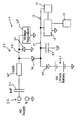
- the drawing is a schematic diagrammatic representation of a preferred form of alarm 10.
- the alarm has an alarm circuit 12 which includes detection means 14 typically in the form of an ionisation chamber, an audible alarm 16 and main control circuitry 18.
- a piezo-electric buzzer may be provided as the audible alarm and power is supplied to the alarm from a battery 20, such as a lithium battery.
- a visual alarm may also be provided. These are contained in a main housing (not shown in the drawings).
- the alarm is typically a smoke alarm although it will be appreciated that the invention is equally applicable to an alarm for detecting other air pollutants such as carbon monoxide, radon or the like.
- the battery 20 has a forward biased diode 22 which serves as a blocking diode to prevent reverse current flowing into the battery.
- the alarm also has a power supply circuit 24 which has suitable means in the form of terminals 26 for connection to an external AC power supply, a live rail 32 of the power supply circuit being connectable to the AC live.
- the power supply circuit 24 includes a voltage regulator 28 and diode 30 to provide half wave rectification of the AC input. Power from the live rail 32 of the power supply circuit is applied to the alarm circuit 12 by way of a further diode 34 which serves to prevent reverse current flowing from the battery into the power supply circuit.
- a smoothing capacitor 40 is provided on the supply line 42 to the alarm circuit 12.
- the power supply circuit 24 also has a series capacitance 36 and resistance 38 in the power rail 32 which, together with the remaining circuit, act as a potential divider to provide a voltage drop across the capacitance 36 and resistance 38 and provide a set voltage for the alarm circuit.
- the resistance 38 also limits current surges which may be caused by transients in the AC power supply.
- the capacitance 36 is set at a value which reduces the current supplied to the alarm circuit 12 to a level which is too low to energise the audible alarm 16 in an alarm state but is at a level to provide standby power to the main control circuitry 18 and the ionisation chamber 14.
- a typical value for capacitance 36 is about 270pF or 1 nF and can be in the range 47nF to 100pF.
- the battery 20 When the audible alarm 16 is triggered, the battery 20 provides sufficient power to energise the alarm.
- the battery is typically a high capacity, non-rechargeable, sealed battery which may be capable of supplying the necessary power for the audible alarm 16 for its entire life, which could be as long as 10 years.
- the sealed battery may have a lower capacity (with environmental and cost benefits) than would be required for a solely battery-powered alarm with a similar design life.
- circuits used in conventional alarms monitor the voltage across the power supply while applying a significant current load in order to determine battery condition. If an ac derived supply is used that is capable of providing significant current (as used by currently available ac alarms), the monitored voltage may be determined by the ac derived supply condition rather than the battery, resulting in a false indication of battery condition.
- the present invention requires an ac derived current that is typically much lower than the applied current load, so the true battery condition can be monitored directly from the circuits' supply without being significantly affected by the presence of the ac supply.
- the power saving is best illustrated by the following example.
- a typical current for driving the audible alarm would be 70mA and a current of 10 ⁇ A for standby operation. These figures are approximate but are the right order of magnitude.
- a capacitance/resistance voltage divider in the power supply circuit is used to provide the current for the alarm with much lower power dissipation.
- capacitance 36 and resistance 38 are chosen such that the instantaneous rectified voltage provided by the AC supply to the alarm circuit 12 is always higher than the voltage that would otherwise be provided by the battery (while providing standby current). This ensures that the diode 22 is always reverse biased, preventing current being drawn from the battery during standby.
- the audible alarm 16 is energized, the alarm circuit 12 draws an increased current and the voltage applied to the alarm circuit 12 drops. The effect is that the diode 22 becomes forward biased and the required current for the audible alarm 16 is supplied by the battery 20.
- the smoothing capacitance 40 should be large enough to ensure that the rectified voltage never drops below the battery voltage on standby. Based on a 10 ⁇ A load and a 50Hz AC supply, a typical capacitance value of 0.47 ⁇ F will prevent the voltage applied to the alarm circuit 12 dropping by more than around 0.2V.
- the alarm 10 may also be provided with a disconnect means (not shown) in series with the battery 20 which disconnects the battery from the alarm circuit 12, for example during shipping of the alarm.
- the disconnect means may be in the form of an electrical switch in series with the battery. The switch is closed to connect the battery and activate the alarm.
- the switch can be a conventional self contained device or an equivalent, such as an insulating tab between two electrical contacts in the battery line that is pulled out to close the circuit.
- disconnect means is an electronic switch which is activated by opening an electrical circuit. This is typically a shorting link that is pulled out to activate the alarm. This method has the advantage of being failsafe, i.e. opening the circuit (which is the most likely failure mechanism) will activate the alarm.
- a further form of disconnect means is an electrical switch connected to an input of a microcontroller in the alarm. Operation of the switch causes the microcontroller to change its operating mode between 'sleep' (very little power taken from the battery) and active. The battery is not electrically isolated using this method but the consequences are similar. As with the previous method, the switch can be configured to be failsafe (open circuit to activate the alarm).
- the disconnect means can be operated directly (by pulling out a tab or operating a switch) or indirectly (the alarm is activated automatically when fitted to its mounting plate).
Landscapes
- Business, Economics & Management (AREA)
- Emergency Management (AREA)
- Physics & Mathematics (AREA)
- General Physics & Mathematics (AREA)
- Emergency Alarm Devices (AREA)
- Fire-Detection Mechanisms (AREA)
Claims (10)
- Alarme pour détecter un rayonnement et/ou des polluants tels que la fumée, le monoxyde de carbone ou similaire, l'alarme comprenant :un circuit d'alarme (12) comprenant des moyens de détection (14) pour détecter lesdits rayonnement et/ou polluants, et une alarme audible (16) ;un circuit d'alimentation (24) pouvant être connecté à une alimentation alternative externe ; etune batterie (20) ;caractérisée en ce que :ledit circuit d'alimentation (24) est configuré pour fournir une puissance de veille au dit circuit d'alarme (12) ;ladite batterie (20) est configurée pour fournir une puissance à ladite alarme audible (16) lorsque ladite alarme est alimentée ; etdans laquelle ledit circuit d'alimentation (20) est configuré pour fournir du courant au dit circuit d'alarme (12) à un niveau inférieur à celui nécessaire pour alimenter ladite alarme audible (16).
- Alarme selon la revendication 1, dans laquelle ledit circuit d'alimentation (24) comprend des moyens (36, 38) pour réduire le courant fourni au dit circuit d'alarme (12) à un niveau inférieur à celui nécessaire pour alimenter ladite alarme audible (16).
- Alarme selon la revendication 2, dans laquelle lesdits moyens comprennent un diviseur de tension.
- Alarme selon la revendication 2, dans laquelle lesdits moyens comprennent une capacitance (36) dans une ligne d'alimentation (32) dudit circuit d'alimentation (24).
- Alarme selon la revendication 4, dans laquelle ladite capacitance a une valeur de 1 nF ou moins.
- Alarme selon la revendication 4, dans laquelle ladite alarme est une alarme de 9 V et ladite capacitance a une valeur de 300 pF ou moins.
- Alarme selon la revendication 6, dans laquelle ladite capacitance a une valeur de 270 pF.
- Alarme selon l'une quelconque des revendications précédentes, dans laquelle ledit circuit d'alimentation est configuré pour fournir un courant au dit circuit d'alarme (12) qui n'est pas supérieur à 50 µA.
- Alarme selon l'une quelconque des revendications précédentes, dans laquelle ledit circuit d'alimentation est configuré pour fournir un courant au dit circuit d'alarme (12) qui n'est pas supérieur à 20 µA.
- Alarme selon l'une quelconque des revendications précédentes, dans laquelle ledit circuit d'alimentation est configuré pour fournir un courant au dit circuit d'alarme (12) qui n'est pas supérieur à 10 µA.
Applications Claiming Priority (2)
| Application Number | Priority Date | Filing Date | Title |
|---|---|---|---|
| GBGB0900382.3A GB0900382D0 (en) | 2009-01-10 | 2009-01-10 | Alarm |
| PCT/GB2010/000026 WO2010079336A1 (fr) | 2009-01-10 | 2010-01-11 | Alarme connectable à un bloc d'alimentation en c.a. externe pour alimentation de remplacement et comprenant une batterie |
Publications (2)
| Publication Number | Publication Date |
|---|---|
| EP2377109A1 EP2377109A1 (fr) | 2011-10-19 |
| EP2377109B1 true EP2377109B1 (fr) | 2013-01-09 |
Family
ID=40379410
Family Applications (1)
| Application Number | Title | Priority Date | Filing Date |
|---|---|---|---|
| EP10701032A Active EP2377109B1 (fr) | 2009-01-10 | 2010-01-11 | Alarme connectable à un bloc d'alimentation en c.a. externe pour alimentation de remplacement et comprenant une batterie |
Country Status (7)
| Country | Link |
|---|---|
| US (1) | US8648730B2 (fr) |
| EP (1) | EP2377109B1 (fr) |
| AU (1) | AU2010204223B2 (fr) |
| CA (1) | CA2755560A1 (fr) |
| DK (1) | DK2377109T3 (fr) |
| GB (1) | GB0900382D0 (fr) |
| WO (1) | WO2010079336A1 (fr) |
Families Citing this family (7)
| Publication number | Priority date | Publication date | Assignee | Title |
|---|---|---|---|---|
| GB2508033B (en) * | 2012-11-20 | 2016-02-17 | Sprue Safety Products Ltd | Low power detection and alarm |
| DE102014017187A1 (de) * | 2014-10-29 | 2016-05-04 | iHaus AG | Neue Gebäudeautomation |
| USD772821S1 (en) | 2015-06-11 | 2016-11-29 | Oculus Vr, Llc | Remote control unit |
| US9801295B2 (en) | 2015-11-05 | 2017-10-24 | Oculus Vr, Llc | Remote control unit with lanyard attachment mechanism |
| US9763348B2 (en) | 2015-11-06 | 2017-09-12 | Oculus Vr, Llc | Remote control unit with battery retention mechanism |
| US9722235B2 (en) * | 2015-12-11 | 2017-08-01 | Oculus Vr, Llc | Remote control unit with battery isolation tab |
| AU2021245122A1 (en) * | 2021-02-18 | 2022-01-13 | Emerald Planet Environmental Pty Ltd | Smoke alarm |
Family Cites Families (9)
| Publication number | Priority date | Publication date | Assignee | Title |
|---|---|---|---|---|
| US4812827A (en) | 1985-11-12 | 1989-03-14 | Scripps Keith A | Detector and light assembly |
| US4972181A (en) * | 1987-02-05 | 1990-11-20 | Fyrnetics, Inc. | A. C. powered smoke detector with back-up battery supervision circuit |
| US5257007A (en) * | 1991-10-01 | 1993-10-26 | M-Tec Corporation | Portable security system |
| DE59409457D1 (de) * | 1993-01-30 | 2000-08-24 | Thomson Brandt Gmbh | Videorecorder |
| AUPM744794A0 (en) * | 1994-08-15 | 1994-09-08 | Garrick, Gilbert Alain Lindsay | Smoke alarm system with standby battery and elv reactive primary power supply |
| US5726573A (en) * | 1995-09-15 | 1998-03-10 | International Business Machines Corporation | Test circuit for back-up battery with protection during test mode |
| AUPP133098A0 (en) | 1998-01-14 | 1998-02-05 | Fyrnetics (Hong Kong) Limited | Improvement to fire alarms |
| US6362743B1 (en) * | 1999-09-09 | 2002-03-26 | Ranco Incorporated Of Delaware | Smoke alarm with dual sensing technologies and dual power sources |
| US7940167B2 (en) * | 2008-09-03 | 2011-05-10 | Lutron Electronics Co., Inc. | Battery-powered occupancy sensor |
-
2009
- 2009-01-10 GB GBGB0900382.3A patent/GB0900382D0/en not_active Ceased
-
2010
- 2010-01-11 DK DK10701032.4T patent/DK2377109T3/da active
- 2010-01-11 WO PCT/GB2010/000026 patent/WO2010079336A1/fr not_active Ceased
- 2010-01-11 CA CA2755560A patent/CA2755560A1/fr not_active Abandoned
- 2010-01-11 US US13/143,816 patent/US8648730B2/en active Active
- 2010-01-11 AU AU2010204223A patent/AU2010204223B2/en not_active Ceased
- 2010-01-11 EP EP10701032A patent/EP2377109B1/fr active Active
Also Published As
| Publication number | Publication date |
|---|---|
| AU2010204223B2 (en) | 2015-08-06 |
| US8648730B2 (en) | 2014-02-11 |
| WO2010079336A1 (fr) | 2010-07-15 |
| DK2377109T3 (da) | 2013-04-02 |
| EP2377109A1 (fr) | 2011-10-19 |
| GB0900382D0 (en) | 2009-02-11 |
| US20110304469A1 (en) | 2011-12-15 |
| CA2755560A1 (fr) | 2010-07-15 |
| AU2010204223A1 (en) | 2011-08-04 |
Similar Documents
| Publication | Publication Date | Title |
|---|---|---|
| EP2377109B1 (fr) | Alarme connectable à un bloc d'alimentation en c.a. externe pour alimentation de remplacement et comprenant une batterie | |
| US20080031752A1 (en) | Sump pump control system | |
| US20080031751A1 (en) | Sump pump control system | |
| KR101320670B1 (ko) | 엘이디 조명의 충전시스템 및 정전감지 장치 | |
| US20110313583A1 (en) | Integrated Wireless Power Control Device | |
| US20110215919A1 (en) | Apparatus and Method for Power and Performance Monitoring of Electric Appliances | |
| EP2923345B1 (fr) | Détection et alarme fonctionnant à faible puissance | |
| US7671538B2 (en) | Method and system for economical emergency activation of electrical devices | |
| CN209913577U (zh) | 物联网低压台区配变智能断路器控制器 | |
| KR20190093405A (ko) | 리튬 이온 배터리 호환 배터리 컨트롤 장치 및 그 제어 방법 | |
| JPWO2006051843A1 (ja) | 電源装置 | |
| CN206803514U (zh) | 安全装置及电热水器 | |
| WO2016089630A2 (fr) | Système de détection de fumée interconnecté à une batterie, avec relais de passage à fil unique ca et cc | |
| ES2221091T3 (es) | Dispositivo de control por microprocesador con proteccion contra las subtensiones. | |
| US12609552B1 (en) | Battery charger and method of control with fast charge mode | |
| KR101810426B1 (ko) | 듀얼 모드 전원 공급 장치 | |
| CN212587940U (zh) | 一种电气自动化用配电柜 | |
| JP6830193B2 (ja) | 電力変換装置、電力変換システム | |
| JP2003289634A (ja) | コンセント装置 | |
| KR20000013542A (ko) | 과부하 경보 및 표시장치 | |
| CN215528696U (zh) | 一种基于直流电源的供电保护电路 | |
| JP6045321B2 (ja) | 保護継電器 | |
| JP4627364B2 (ja) | 電流検出装置 | |
| CN209819898U (zh) | 一种电热水器 | |
| KR20050077911A (ko) | 간판등 제어의 안전성을 높이는 방법 |
Legal Events
| Date | Code | Title | Description |
|---|---|---|---|
| PUAI | Public reference made under article 153(3) epc to a published international application that has entered the european phase |
Free format text: ORIGINAL CODE: 0009012 |
|
| 17P | Request for examination filed |
Effective date: 20110711 |
|
| AK | Designated contracting states |
Kind code of ref document: A1 Designated state(s): AT BE BG CH CY CZ DE DK EE ES FI FR GB GR HR HU IE IS IT LI LT LU LV MC MK MT NL NO PL PT RO SE SI SK SM TR |
|
| DAX | Request for extension of the european patent (deleted) | ||
| REG | Reference to a national code |
Ref country code: DE Ref legal event code: R079 Ref document number: 602010004523 Country of ref document: DE Free format text: PREVIOUS MAIN CLASS: G08B0017100000 Ipc: G08B0017000000 |
|
| RIC1 | Information provided on ipc code assigned before grant |
Ipc: G08B 17/10 20060101ALI20120420BHEP Ipc: G08B 17/00 20060101AFI20120420BHEP |
|
| GRAP | Despatch of communication of intention to grant a patent |
Free format text: ORIGINAL CODE: EPIDOSNIGR1 |
|
| GRAS | Grant fee paid |
Free format text: ORIGINAL CODE: EPIDOSNIGR3 |
|
| GRAA | (expected) grant |
Free format text: ORIGINAL CODE: 0009210 |
|
| AK | Designated contracting states |
Kind code of ref document: B1 Designated state(s): AT BE BG CH CY CZ DE DK EE ES FI FR GB GR HR HU IE IS IT LI LT LU LV MC MK MT NL NO PL PT RO SE SI SK SM TR |
|
| REG | Reference to a national code |
Ref country code: GB Ref legal event code: FG4D |
|
| REG | Reference to a national code |
Ref country code: AT Ref legal event code: REF Ref document number: 593147 Country of ref document: AT Kind code of ref document: T Effective date: 20130115 Ref country code: CH Ref legal event code: EP |
|
| REG | Reference to a national code |
Ref country code: IE Ref legal event code: FG4D |
|
| REG | Reference to a national code |
Ref country code: DE Ref legal event code: R096 Ref document number: 602010004523 Country of ref document: DE Effective date: 20130307 |
|
| REG | Reference to a national code |
Ref country code: DK Ref legal event code: T3 |
|
| REG | Reference to a national code |
Ref country code: SE Ref legal event code: TRGR |
|
| PG25 | Lapsed in a contracting state [announced via postgrant information from national office to epo] |
Ref country code: SI Free format text: LAPSE BECAUSE OF FAILURE TO SUBMIT A TRANSLATION OF THE DESCRIPTION OR TO PAY THE FEE WITHIN THE PRESCRIBED TIME-LIMIT Effective date: 20130109 |
|
| REG | Reference to a national code |
Ref country code: NL Ref legal event code: VDEP Effective date: 20130109 |
|
| REG | Reference to a national code |
Ref country code: AT Ref legal event code: MK05 Ref document number: 593147 Country of ref document: AT Kind code of ref document: T Effective date: 20130109 |
|
| REG | Reference to a national code |
Ref country code: LT Ref legal event code: MG4D |
|
| PG25 | Lapsed in a contracting state [announced via postgrant information from national office to epo] |
Ref country code: AT Free format text: LAPSE BECAUSE OF FAILURE TO SUBMIT A TRANSLATION OF THE DESCRIPTION OR TO PAY THE FEE WITHIN THE PRESCRIBED TIME-LIMIT Effective date: 20130109 Ref country code: BE Free format text: LAPSE BECAUSE OF FAILURE TO SUBMIT A TRANSLATION OF THE DESCRIPTION OR TO PAY THE FEE WITHIN THE PRESCRIBED TIME-LIMIT Effective date: 20130109 Ref country code: BG Free format text: LAPSE BECAUSE OF FAILURE TO SUBMIT A TRANSLATION OF THE DESCRIPTION OR TO PAY THE FEE WITHIN THE PRESCRIBED TIME-LIMIT Effective date: 20130409 Ref country code: NO Free format text: LAPSE BECAUSE OF FAILURE TO SUBMIT A TRANSLATION OF THE DESCRIPTION OR TO PAY THE FEE WITHIN THE PRESCRIBED TIME-LIMIT Effective date: 20130409 Ref country code: ES Free format text: LAPSE BECAUSE OF FAILURE TO SUBMIT A TRANSLATION OF THE DESCRIPTION OR TO PAY THE FEE WITHIN THE PRESCRIBED TIME-LIMIT Effective date: 20130420 Ref country code: LT Free format text: LAPSE BECAUSE OF FAILURE TO SUBMIT A TRANSLATION OF THE DESCRIPTION OR TO PAY THE FEE WITHIN THE PRESCRIBED TIME-LIMIT Effective date: 20130109 Ref country code: IS Free format text: LAPSE BECAUSE OF FAILURE TO SUBMIT A TRANSLATION OF THE DESCRIPTION OR TO PAY THE FEE WITHIN THE PRESCRIBED TIME-LIMIT Effective date: 20130509 |
|
| PG25 | Lapsed in a contracting state [announced via postgrant information from national office to epo] |
Ref country code: PT Free format text: LAPSE BECAUSE OF FAILURE TO SUBMIT A TRANSLATION OF THE DESCRIPTION OR TO PAY THE FEE WITHIN THE PRESCRIBED TIME-LIMIT Effective date: 20130509 Ref country code: FI Free format text: LAPSE BECAUSE OF FAILURE TO SUBMIT A TRANSLATION OF THE DESCRIPTION OR TO PAY THE FEE WITHIN THE PRESCRIBED TIME-LIMIT Effective date: 20130109 Ref country code: NL Free format text: LAPSE BECAUSE OF FAILURE TO SUBMIT A TRANSLATION OF THE DESCRIPTION OR TO PAY THE FEE WITHIN THE PRESCRIBED TIME-LIMIT Effective date: 20130109 Ref country code: MC Free format text: LAPSE BECAUSE OF NON-PAYMENT OF DUE FEES Effective date: 20130131 Ref country code: LV Free format text: LAPSE BECAUSE OF FAILURE TO SUBMIT A TRANSLATION OF THE DESCRIPTION OR TO PAY THE FEE WITHIN THE PRESCRIBED TIME-LIMIT Effective date: 20130109 Ref country code: PL Free format text: LAPSE BECAUSE OF FAILURE TO SUBMIT A TRANSLATION OF THE DESCRIPTION OR TO PAY THE FEE WITHIN THE PRESCRIBED TIME-LIMIT Effective date: 20130109 Ref country code: GR Free format text: LAPSE BECAUSE OF FAILURE TO SUBMIT A TRANSLATION OF THE DESCRIPTION OR TO PAY THE FEE WITHIN THE PRESCRIBED TIME-LIMIT Effective date: 20130410 |
|
| PG25 | Lapsed in a contracting state [announced via postgrant information from national office to epo] |
Ref country code: HR Free format text: LAPSE BECAUSE OF FAILURE TO SUBMIT A TRANSLATION OF THE DESCRIPTION OR TO PAY THE FEE WITHIN THE PRESCRIBED TIME-LIMIT Effective date: 20130109 |
|
| PG25 | Lapsed in a contracting state [announced via postgrant information from national office to epo] |
Ref country code: CZ Free format text: LAPSE BECAUSE OF FAILURE TO SUBMIT A TRANSLATION OF THE DESCRIPTION OR TO PAY THE FEE WITHIN THE PRESCRIBED TIME-LIMIT Effective date: 20130109 Ref country code: RO Free format text: LAPSE BECAUSE OF FAILURE TO SUBMIT A TRANSLATION OF THE DESCRIPTION OR TO PAY THE FEE WITHIN THE PRESCRIBED TIME-LIMIT Effective date: 20130109 Ref country code: SK Free format text: LAPSE BECAUSE OF FAILURE TO SUBMIT A TRANSLATION OF THE DESCRIPTION OR TO PAY THE FEE WITHIN THE PRESCRIBED TIME-LIMIT Effective date: 20130109 Ref country code: EE Free format text: LAPSE BECAUSE OF FAILURE TO SUBMIT A TRANSLATION OF THE DESCRIPTION OR TO PAY THE FEE WITHIN THE PRESCRIBED TIME-LIMIT Effective date: 20130109 |
|
| PLBE | No opposition filed within time limit |
Free format text: ORIGINAL CODE: 0009261 |
|
| STAA | Information on the status of an ep patent application or granted ep patent |
Free format text: STATUS: NO OPPOSITION FILED WITHIN TIME LIMIT |
|
| PG25 | Lapsed in a contracting state [announced via postgrant information from national office to epo] |
Ref country code: CY Free format text: LAPSE BECAUSE OF FAILURE TO SUBMIT A TRANSLATION OF THE DESCRIPTION OR TO PAY THE FEE WITHIN THE PRESCRIBED TIME-LIMIT Effective date: 20130109 |
|
| 26N | No opposition filed |
Effective date: 20131010 |
|
| PG25 | Lapsed in a contracting state [announced via postgrant information from national office to epo] |
Ref country code: IT Free format text: LAPSE BECAUSE OF FAILURE TO SUBMIT A TRANSLATION OF THE DESCRIPTION OR TO PAY THE FEE WITHIN THE PRESCRIBED TIME-LIMIT Effective date: 20130109 |
|
| REG | Reference to a national code |
Ref country code: DE Ref legal event code: R097 Ref document number: 602010004523 Country of ref document: DE Effective date: 20131010 |
|
| PG25 | Lapsed in a contracting state [announced via postgrant information from national office to epo] |
Ref country code: MT Free format text: LAPSE BECAUSE OF FAILURE TO SUBMIT A TRANSLATION OF THE DESCRIPTION OR TO PAY THE FEE WITHIN THE PRESCRIBED TIME-LIMIT Effective date: 20130109 |
|
| REG | Reference to a national code |
Ref country code: CH Ref legal event code: PL |
|
| PG25 | Lapsed in a contracting state [announced via postgrant information from national office to epo] |
Ref country code: CH Free format text: LAPSE BECAUSE OF NON-PAYMENT OF DUE FEES Effective date: 20140131 Ref country code: LI Free format text: LAPSE BECAUSE OF NON-PAYMENT OF DUE FEES Effective date: 20140131 |
|
| PG25 | Lapsed in a contracting state [announced via postgrant information from national office to epo] |
Ref country code: SM Free format text: LAPSE BECAUSE OF FAILURE TO SUBMIT A TRANSLATION OF THE DESCRIPTION OR TO PAY THE FEE WITHIN THE PRESCRIBED TIME-LIMIT Effective date: 20130109 |
|
| PG25 | Lapsed in a contracting state [announced via postgrant information from national office to epo] |
Ref country code: TR Free format text: LAPSE BECAUSE OF FAILURE TO SUBMIT A TRANSLATION OF THE DESCRIPTION OR TO PAY THE FEE WITHIN THE PRESCRIBED TIME-LIMIT Effective date: 20130109 |
|
| PG25 | Lapsed in a contracting state [announced via postgrant information from national office to epo] |
Ref country code: LU Free format text: LAPSE BECAUSE OF NON-PAYMENT OF DUE FEES Effective date: 20130111 Ref country code: HU Free format text: LAPSE BECAUSE OF FAILURE TO SUBMIT A TRANSLATION OF THE DESCRIPTION OR TO PAY THE FEE WITHIN THE PRESCRIBED TIME-LIMIT; INVALID AB INITIO Effective date: 20100111 Ref country code: MK Free format text: LAPSE BECAUSE OF FAILURE TO SUBMIT A TRANSLATION OF THE DESCRIPTION OR TO PAY THE FEE WITHIN THE PRESCRIBED TIME-LIMIT Effective date: 20130109 |
|
| REG | Reference to a national code |
Ref country code: FR Ref legal event code: PLFP Year of fee payment: 7 |
|
| REG | Reference to a national code |
Ref country code: FR Ref legal event code: PLFP Year of fee payment: 8 |
|
| REG | Reference to a national code |
Ref country code: FR Ref legal event code: PLFP Year of fee payment: 9 |
|
| PGFP | Annual fee paid to national office [announced via postgrant information from national office to epo] |
Ref country code: CH Payment date: 20190117 Year of fee payment: 17 Ref country code: FR Payment date: 20190111 Year of fee payment: 10 |
|
| PGFP | Annual fee paid to national office [announced via postgrant information from national office to epo] |
Ref country code: DK Payment date: 20190110 Year of fee payment: 10 Ref country code: SE Payment date: 20190110 Year of fee payment: 10 |
|
| REG | Reference to a national code |
Ref country code: DE Ref legal event code: R119 Ref document number: 602010004523 Country of ref document: DE |
|
| REG | Reference to a national code |
Ref country code: DK Ref legal event code: EBP Effective date: 20200131 |
|
| REG | Reference to a national code |
Ref country code: SE Ref legal event code: EUG |
|
| REG | Reference to a national code |
Ref country code: SE Ref legal event code: EUG |
|
| PG25 | Lapsed in a contracting state [announced via postgrant information from national office to epo] |
Ref country code: FR Free format text: LAPSE BECAUSE OF NON-PAYMENT OF DUE FEES Effective date: 20200131 Ref country code: SE Free format text: LAPSE BECAUSE OF NON-PAYMENT OF DUE FEES Effective date: 20200112 Ref country code: DE Free format text: LAPSE BECAUSE OF NON-PAYMENT OF DUE FEES Effective date: 20200801 |
|
| PG25 | Lapsed in a contracting state [announced via postgrant information from national office to epo] |
Ref country code: DK Free format text: LAPSE BECAUSE OF NON-PAYMENT OF DUE FEES Effective date: 20200131 |
|
| P01 | Opt-out of the competence of the unified patent court (upc) registered |
Effective date: 20230530 |
|
| PGFP | Annual fee paid to national office [announced via postgrant information from national office to epo] |
Ref country code: GB Payment date: 20260113 Year of fee payment: 17 |
|
| PGFP | Annual fee paid to national office [announced via postgrant information from national office to epo] |
Ref country code: IE Payment date: 20260108 Year of fee payment: 17 |