EP2377246B1 - Vorrichtung und verfahren für optische emissionsspektroskopie - Google Patents
Vorrichtung und verfahren für optische emissionsspektroskopie Download PDFInfo
- Publication number
- EP2377246B1 EP2377246B1 EP09799063.4A EP09799063A EP2377246B1 EP 2377246 B1 EP2377246 B1 EP 2377246B1 EP 09799063 A EP09799063 A EP 09799063A EP 2377246 B1 EP2377246 B1 EP 2377246B1
- Authority
- EP
- European Patent Office
- Prior art keywords
- current
- spark
- peaks
- waveform
- modulated
- Prior art date
- Legal status (The legal status is an assumption and is not a legal conclusion. Google has not performed a legal analysis and makes no representation as to the accuracy of the status listed.)
- Active
Links
Images


Classifications
-
- G—PHYSICS
- G01—MEASURING; TESTING
- G01J—MEASUREMENT OF INTENSITY, VELOCITY, SPECTRAL CONTENT, POLARISATION, PHASE OR PULSE CHARACTERISTICS OF INFRARED, VISIBLE OR ULTRAVIOLET LIGHT; COLORIMETRY; RADIATION PYROMETRY
- G01J3/00—Spectrometry; Spectrophotometry; Monochromators; Measuring colours
- G01J3/28—Investigating the spectrum
- G01J3/443—Emission spectrometry
-
- G—PHYSICS
- G01—MEASURING; TESTING
- G01N—INVESTIGATING OR ANALYSING MATERIALS BY DETERMINING THEIR CHEMICAL OR PHYSICAL PROPERTIES
- G01N21/00—Investigating or analysing materials by the use of optical means, i.e. using sub-millimetre waves, infrared, visible or ultraviolet light
- G01N21/62—Systems in which the material investigated is excited whereby it emits light or causes a change in wavelength of the incident light
- G01N21/66—Systems in which the material investigated is excited whereby it emits light or causes a change in wavelength of the incident light electrically excited, e.g. electroluminescence
- G01N21/67—Systems in which the material investigated is excited whereby it emits light or causes a change in wavelength of the incident light electrically excited, e.g. electroluminescence using electric arcs or discharges
-
- H—ELECTRICITY
- H03—ELECTRONIC CIRCUITRY
- H03K—PULSE TECHNIQUE
- H03K3/00—Circuits for generating electric pulses; Monostable, bistable or multistable circuits
- H03K3/02—Generators characterised by the type of circuit or by the means used for producing pulses
- H03K3/53—Generators characterised by the type of circuit or by the means used for producing pulses by the use of an energy-accumulating element discharged through the load by a switching device controlled by an external signal and not incorporating positive feedback
- H03K3/57—Generators characterised by the type of circuit or by the means used for producing pulses by the use of an energy-accumulating element discharged through the load by a switching device controlled by an external signal and not incorporating positive feedback the switching device being a semiconductor device
-
- H—ELECTRICITY
- H03—ELECTRONIC CIRCUITRY
- H03K—PULSE TECHNIQUE
- H03K4/00—Generating pulses having essentially a finite slope or stepped portions
- H03K4/02—Generating pulses having essentially a finite slope or stepped portions having stepped portions, e.g. staircase waveform
Definitions
- the present invention relates to apparatus and methods for optical emission spectroscopy, in particular, but not exclusively, to a spark generator, a spectrometer and a method for optical emission spectroscopy.
- Optical emission spectroscopy also termed atomic emission spectroscopy (AES) is a technique for the elemental analysis of samples and is particularly useful, for example, in the analysis of solid, metallic samples.
- the present invention relates to OES wherein a spark (herein used to refer to any electrical spark, arc or discharge) is used to rapidly vaporise a sample and excite elements in the vapourised sample, i.e. so-called spark OES.
- spark herein used to refer to any electrical spark, arc or discharge
- glow OES Light is emitted by the excited elements of the sample as transitions occur from an excited state to a lower energy state.
- Each element emits light of discrete wavelengths characteristic of its electronic structure, which are also termed spectral lines.
- a spark optical emission spectrometer thus includes a spark generator for exciting the elements in the sample to emit light, an optical system for dispersing the emitted light into discrete wavelengths, a detection system for detecting the light intensity of the dispersed light and a data storage and processing system for storing and processing signals from the detection system representing the light intensity.
- a succession of sparks is typically employed and the resulting data generated from the sparks is accumulated for processing.
- a spark generator for producing a sequence of sparks for exciting a sample in OES should preferably produce sparks having a stable energy output and high degree of reproducibility for high accuracy of measurements.
- analogue spark generators in which sparks are generated in an unmodulated way by the discharge of a capacitor through a resistance and an inductance (RLC circuit), do not permit a high amount of control over the current waveform or profile of the spark and hence the reproducibility is low. Accordingly, the accuracy of measurement of components in a sample is adversely affected.
- the current waveform of an analogue spark source is generally characterised by a relatively slow rise of the spark current (compared to the digital sources described below) to a broad peak before a gradual fall or decay of the current in an exponential manner over a longer time period. It has been found that this type of unmodulated current profile is not well suited to the analysis of trace elements in samples. Although it may be better for analysis of alloying elements in metals than trace elements, even in that case the analogue generated spark still leads to the poor measurement accuracy mentioned above due to poor spark reproducibility.
- So-called digital spark generators e.g. as described in EP 396 291 B1 , which generate modulated sparks are known and these have sought to address some of the above issues.
- a spark generator including means for measuring the spark current during the spark, comparing the spark current to a reference current and adjusting the spark current to a pre-determined value dependent on the reference current.
- the sampling rate for the reference comparison is said to be 50-200 kHz.
- the reference current is stored on a computer as part of a program for the spark current waveform.
- the modulated current waveform described in the prior art generally has a single initial peak of high amplitude (high current) and of relatively short duration followed by a longer lasting modulated decay of low current, which resembles something of a current plateau.
- the high amplitude peak may be a factor of 5 more intense than the current plateau.
- Such a waveform is shown schematically in Figure 4 of EP 396 291 B1 .
- the initial high current peak is described as being mainly for use in the evaporation of the sample and the longer lasting current is for exciting the atoms in the vapourised sample. It has been found that this type of current profile is better than the profile of the analogue spark source for detecting trace elements but is not so well suited to the analysis of alloying elements in metal alloy samples.
- JP 8-159973 A and EP 318 900 A2 another type of spark source is described in which two portions of current are produced. A high current portion is produced first which is a single peak and a low current portion is produced second which comprises two or three peaks of progressively lower intensity.
- These spark sources suffer from a lack of control due to the use of passive circuitry. In particular, the amplitudes and durations of current peaks are fixed by different values of capacitors and inductors.
- EP 84566 A is disclosed a spark source employing a decaying oscillatory current source again employing passive circuitry (i.e. a resonant LC circuit) and therefore also suffers from a lack of control. The current envelope simply decreases along an exponentially decaying curve with peak frequency being determined by the resonant frequency of the circuit.
- CCD charge coupled device
- a spark generator for generating a spark for optical emission spectroscopy (OES) according to claim 1.
- an optical emission spectrometer comprising the spark generator according to the present invention.
- the spark generator and the optical emission spectrometer according to the present invention are preferably for carrying out the method according to the present invention described below.
- the method is performed by the optical emission spectrometer according to the present invention.
- the present invention has numerous advantages including those now specifically described. Other advantages will be apparent from the description below.
- the present invention allows a more controlled separation in time of the different phases in the spark process.
- the invention allows a better separation of the phase of pre-treatment (re-melting and structure refining) and vaporisation of the sample surface from the phase of excitation of the resultant vapours for optical analysis.
- the use of programmable current sources permits variation of the inter-peak duration, the rise time, the peak amplitude and the number of high current peaks. This degree of control is not possible with either the cascaded current sources of JP 8-159973 A and EP 318 900 A2 or the decaying oscillatory current source of EP 84566 A .
- first modulated current portion comprising a plurality of relatively high current and high gradient peaks has been found to allow a better control of the high energy delivery to the sample surface.
- This high energy delivery conditions and vaporises the sample surface in a better controlled way than a single high current peak at the beginning of the spark. More specifically, this feature allows controlling separately the magnitude of the spark plasma energy (i.e. temperature) and duration of this energy transfer to the sample surface, during the high energy phase.
- modulating the energy delivered to the spark in the claimed way allows alternating rapidly between a high energy plasma stage for vaporizing and a lower energy stage which promotes stabilization phenomena at the sample surface while allowing the highest energies of the vapours to relax for optimising the forthcoming analysis phase.
- This feature of the present invention instead is provided by a programmable current source.
- the relatively low current portion of the invention is not a vanishing current but a stabilized and controlled current. The aim of this is to provide the spark with a limited and controlled amount of energy to optimize the excitation of vapours for analysis. In this analytical phase, the energy level and the duration of this energy supply to the vapours can be controlled separately using the present invention.
- the invention enables the determination with good precision of both trace elements and alloying elements in metal samples, in contrast to the prior art methods described above which are better suited to either one of these applications or the other.
- a part of the spark's energy will be used for sample evapouration, a part for atomisation and/or ionisation and a part for excitation.
- the invention may achieve the advantage above because the spark energy is delivered in a plurality of relatively high current high gradient current peaks (i.e. high energy), e.g. in the early part of the waveform, compared to the purely analogue spark source, thus creating more controlled higher temperature zones in the plasma, e.g.
- the most sensitive spectral lines which can be useful in determining trace elements, typically arise from the so-called resonance transitions, such as atomic type transitions (described in tables of spectral lines as U1, U2, ... etc.) and ionic type transitions (described in tables of spectral lines as V1, V2, ... etc.). These have high transition probabilities and can have high energies, e.g. in the range of 7 to 12 eV, and thus are most efficiently excited by the high temperature plasma.
- the use of a plurality of peaks in the high current part of the waveform, which is programmable, of variable amplitude and/or inter-peak duration gives a better degree of control of the duration of the high temperature plasma.
- the detection of alloying elements in metals may be enhanced, compared to the prior art digital spark source described in EP 396 291 B1 , because the spark energy is not concentrated into a single, highly intense current peak at the beginning of the waveform but instead is spread over a plurality of peaks of variable amplitude and/or inter-peak duration so that the waveform is also efficient at promoting lower energy electron transitions (e.g. 2 to 7 eV) which tend to occur later in the spark, mainly in atomic species, and it creates a lower background for these transitions.
- lower energy electron transitions e.g. 2 to 7 eV
- These types of atomic transitions are often less sensitive, i.e. having lower transition probabilities, and as such can be useful in determining alloying elements which otherwise would, due the high concentration of the elements present, produce highly intense spectral lines that could overload the detector.
- TRS time-resolved spectroscopy
- TRS Different time windows can be employed in TRS for different spectral lines.
- the choice of time window depends on the parameters of the spectral line such as its energy.
- the time window can also be chosen to minimise perturbations to the spectral line from, e.g., the source or spectral background interference.
- TRS is, for example, of significant benefit for trace element analysis.
- the present invention has been found to significantly improve precision in the quantitative determination of many compositions (for a given acquisition time) and thereby reduce acquisition times for the same precision.
- the use of a spark having a waveform in accordance with the present invention can reduce the rate of deterioration of the response of a CCD light detector in the environment of an OES instrument.
- the deterioration is due to a photochemical reaction ("quenching") of volatile organic molecules, which are typically present in the low pressure environment of the instrument in small amounts, with intense UV light, such as is produced when using the single intense current peak of the prior art digital spark source.
- the photochemically produced products are then thought to become deposited on the surface of the CCD detector, which lowers the detector sensitivity over time.
- the present invention uses a spark which spreads the high energy over a plurality of peaks of variable amplitude and/or inter-peak duration rather than concentrate the energy into the single intense peak as in the prior art and this is believed to reduce the quenching probability and thereby explaining the observed reduction of the deposition rate on the detector when used with the present invention.
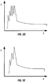
- FIG. 1 plots the spark current (I) against time (t). It can be seen from Figure 1 that the waveform comprises a modulated waveform comprising a first modulated portion of relatively high current denoted by A followed by a second modulated portion of relatively low current denoted by B.
- relatively e.g. relatively high current or gradient or relatively low current or gradient, means relative to the other, e.g., current or gradient.
- relatively high current means a higher current relative to the relatively low current.
- the relatively high current portion A is characterised by being modulated by a plurality of relatively high gradient peaks, labelled as P1-P6 in this example, of variable amplitude and/or inter-peak duration.
- P1-P6 relatively high gradient peaks
- Figure 1 the case of modulation by a plurality of peaks of variable amplitude is shown.
- the sequence of peaks P1-P3 represents modulation of a steep leading edge or current rise (represented by upward arrow r in Figure 1 ) of the high current portion A by relatively high gradient peaks of increasing amplitude.
- the sequence of peaks P3-P6 represents further modulation of the high current portion A by relatively high gradient peaks of decreasing amplitude, which modulate a trailing edge or current fall (represented by the downward arrow f in Figure 1 ) of the high current portion A.
- the first portion (i.e. relatively high current portion) of the waveform comprises an underlying current envelope, i.e. comprising a current rise and a current fall.
- the current rise may be modulated by a plurality of relatively high gradient peaks of increasing amplitude and the current fall may be modulated by a plurality of relatively high gradient peaks of decreasing amplitude.
- other modulations are possible.
- only the current rise of the first portion of the waveform may be modulated by a plurality of the relatively high gradient peaks (preferably of increasing amplitude) with the current fall not having a plurality of relatively high gradient peaks, or vice versa.
- at least the current rise of the first portion of the waveform is modulated by a plurality of the relatively high gradient peaks of variable amplitude and/or inter-peak duration (preferably of increasing amplitude).
- the first relatively high current portion (i.e. first modulated portion) of the waveform may be modulated by at least a plurality of relatively high gradient peaks of a first high amplitude and a plurality of relatively high gradient peaks of a second high amplitude.
- the first relatively high current portion of the waveform may be modulated by a plurality of relatively high gradient peaks of a first high amplitude, followed by a plurality of relatively high gradient peaks of a second high amplitude, optionally followed by a plurality of relatively high gradient peaks of a third high amplitude, which may be the same as the first high amplitude again or a different high amplitude and so on until the relatively low current portion of the waveform.
- FIGS 2A to 2E Schematic representations of various spark current waveforms according to the present invention having relatively high current high gradient peaks of variable amplitude are shown in Figures 2A to 2E .
- Figures 3A and 3B are shown schematic representations of examples of spark current waveforms according to the present invention having relatively high gradient peaks of variable inter-peak duration ( Figure 3A ) and of variable amplitude and variable inter-peak duration ( Figure 3B ).
- FIG. 4 A comparison of a spark of the present invention with a prior art single peak spark is shown in the example in Figure 4 , in which it can be seen that the energy of the spark of the present invention is spread across several peaks in the case of the present invention thereby giving better overall control of the spark energy delivery with respect to amplitude and time. In the low current portion, the two waveforms are superimposed.
- the second relatively low current portion of the waveform (i.e. second modulated portion), e.g. denoted by B in Figure 1 , in the embodiment shown follows the modulation by the plurality of relatively high gradient peaks and preferably is in the form of a longer lasting current (i.e. longer duration than the first relatively high current portion).
- the relatively low current portion is modulated by a relatively low gradient low current which tends toward a current plateau (i.e. a substantially constant current value).
- the plateau is preferably a non-zero plateau. This provides that a limited and controlled amount of energy is provided by the second current portion.
- the second relatively low current portion (i.e. second modulated portion) may be modulated by a relatively low gradient current which modulation is stopped after a pre-determined time such that the low current portion then follows an unmodulated decay, e.g. as results from exponential decay, in a third portion.
- the current waveform is preferably interrupted, e.g. by a short circuit, to terminate the discharge abruptly to reduce afterglow arcing. Such an interruption is shown, for example, in Figure 1 at point SC.
- the relatively low current and low gradient portion (i.e. second modulated portion) is preferably substantially without any modulated peaks, thus including substantially without relatively high gradient peaks.
- the relatively low current portion preferentially excites lower energy atomic transitions, thereby allowing better time separation of these transitions from the higher energy transitions which are preferentially excited by the relatively high current portion of the spark.
- the present invention enables a range of different types of transitions, both atomic and ionic, and both high energy and low energy, to be efficiently excited such that the invention is effective at measuring both trace elements and alloying elements in metallic samples.
- the plurality of relatively high gradient peaks have their variable amplitudes and/or inter-peak durations programmed to suit a particular analytical application, e.g. the waveform may be tailored to one which is effective for measuring the target elements in a given sample.
- the modulated low gradient of the second relatively low current portion may be programmed to suit the particular analytical application.
- the relatively high gradient peaks of variable amplitude and/or inter-peak duration may have either variable amplitudes or variable inter-peak duration (i.e. different time intervals between the peaks) or both.
- the peaks are at least of variable amplitude (i.e. optionally with variable inter-peak duration).
- the high gradient current peaks of the waveform are modulated in terms of their number, their amplitude and/or their inter-peak duration to suit a particular analytical application.
- the number of peaks, their amplitude and/or inter-peak duration are preferably programmable and controlled by a computer which controls the spark generator circuit as described in more detail below.
- the term plurality in relation to the number of current peaks means two or more.
- the number of peaks in the waveform are programmed to suit the sample to be analysed.
- the composition constituting the matrix of the sample e.g. in a metal sample, is a significant factor in determining the number of peaks in the modulation.
- the optimum number of peaks may be experimentally determined and then an appropriate computer program or parameters for a computer program controlling the peak modulation may be selected accordingly.
- the first relatively high current modulated portion is modulated by two or more peaks of variable amplitude and/or inter-peak duration, more preferably three or more.
- the waveform may be programmed to have four, five, six, seven or more peaks.
- Figure 1 shows a waveform according to the present invention having, in its relatively high current portion, three peaks on the current rise and four peaks on the fall (counting the highest peak as part of the rise and the fall) and six peaks in total.
- the first relatively high current modulated portion of the waveform generally comprises a leading edge or rise of the spark current, e.g. rise r shown in Figure 1 .
- This leading edge preferably is modulated by a plurality of the relatively high current high gradient peaks, more preferably of increasing amplitude, more preferably at least three such peaks of increasing amplitude.
- the relatively high current portion of the waveform preferably also comprises a trailing edge or fall, e.g. fall f shown in Figure 1 .
- This trailing edge preferably is modulated by a plurality of the relatively high gradient peaks, more preferably of decreasing amplitude, more preferably at least 2 such peaks of decreasing amplitude.
- variable amplitude in relation to the plurality of relatively high gradient current peaks means that the peaks are not all of the same amplitude and the amplitude of each peak may be independently adjusted, e.g. according to a modulation program.
- the amplitude of each peak may be dependent on one or more reference currents of a modulation program, as described in detail below.
- the high gradient current peaks may each be of different amplitude.
- two or more of the plurality of relatively high gradient current peaks may have the same amplitude provided at least one relatively high gradient current peak is of different amplitude.
- the plurality of relatively high gradient current peaks is programmed to be of relatively high current amplitude.
- the amplitude is preferably programmable on a computer which controls the spark generator circuit.
- the amplitude is programmed to suit a particular analytical application.
- the current amplitude of at least some, more preferably most, most preferably all, of the plurality of peaks is between 15 and 250A, more typically between 20 and 150A.
- the current step (i.e. difference in amplitude) is preferably in the range 1 to 235A, more preferably at least 10A, still more preferably 10 to 40A.
- the relatively high gradient peaks may have a gradient on their rise side in the range 10-60 A/ ⁇ s, preferably 25-55 A/ ⁇ s, more preferably 30-50 A/ ⁇ s, e.g. 40A/ ⁇ s.
- the first portion (i.e. relatively high current portion) of the waveform preferably comprises an underlying current envelope i.e. comprising a current rise and a current fall.
- the current rise may be modulated by a plurality of relatively high gradient peaks of increasing amplitude and/or the current fall may be modulated by a plurality of relatively high gradient peaks of decreasing amplitude.
- other modulations are possible.
- only the current rise of the first portion of the waveform may be modulated by a plurality of the relatively high gradient peaks (preferably of increasing amplitude) with the current fall not having a plurality of relatively high gradient peaks, or vice versa.
- at least the current rise of the first portion of the waveform is modulated by a plurality of the relatively high gradient peaks of variable amplitude and/or inter-peak duration (preferably of increasing amplitude).
- the rise time for the leading edge of the first, high current modulated portion of the waveform i.e. the rise time from the start of the spark to the highest amplitude peak, is preferably in the range 10 to 100 ⁇ s, more preferably 20 to 90 ⁇ s, e.g. 25 to 75 ⁇ s).
- the first modulated relatively high current portion of the waveform is preferably of relatively short duration (i.e. as compared to the second, relatively low current portion).
- the duration of the modulated relatively high current portion of the waveform is preferably in the range 10 to 200 ⁇ s, more preferably 20 to 100 ⁇ s. Whilst it is generally preferable that the first modulated portion of the waveform be shorter than the second modulated portion, in some embodiments the second modulated portion of the waveform may be shorter than the first modulated portion (e.g. a first portion of 100 ⁇ s duration with a shorter second portion of 50 ⁇ s duration).
- the duration of the modulated relatively low current portion of the waveform is preferably in the range 1 to 3000 ⁇ s, more preferably 50 to 2000 ⁇ s and is preferably, although not necessarily, of longer duration than the first modulated portion.
- inter-peak duration herein means the duration between adjacent peaks as measured peak-to-peak.
- variable inter-peak duration in relation to the plurality of relatively high gradient current peaks means peaks that are not all of the same inter-peak duration, i.e. are not all evenly spaced apart in time.
- the inter-peak duration of the peaks may be independently adjusted, e.g. according to a modulation program. For example, the inter-peak duration of the peaks may be dependent on one or more reference currents of a modulation program, as described in detail below.
- the inter-peak duration of the plurality of relatively high gradient peaks is preferably in the range 1 to 100 ⁇ s.
- the relatively low current second modulated portion of the waveform is substantially without any modulated peaks.
- the second modulated portion may have some minor peaks.
- second modulated portion is without any modulated peaks, i.e. no modulated peaks at all.
- the relatively low current second portion is preferably substantially flat (i.e. substantially not sloping) over most of its duration. In that case, the second portion is not a vanishing current but a stabilised and controlled current.
- the low gradient modulation of the relatively low current second portion modulates the current toward a current plateau.
- the average current amplitude of the modulated relatively low current portion is preferably in the range 1 to 60 A, more preferably 5 to 50 A, more preferably 10 to 40 A.
- the low gradient of the second modulated portion of the waveform preferably has a current gradient not more than about 1A/ ⁇ s, more preferably not more than about 0.5A/ ⁇ s and most preferably not more than about 0.2A/ ⁇ s.
- the low gradient of the second modulated portion of the waveform preferably has a current gradient from about 0.1 to about 1A/ ⁇ s.
- the amplitude of the second modulated portion of the waveform is preferably programmable in a controller which controls the spark generator circuit.
- the low gradient modulation of the second relatively low current portion may be stopped after a pre-determined time such that the low current portion then follows an unmodulated decay, e.g. an exponential decay.
- the current waveform is preferably terminated abruptly, e.g. by a short circuit of the current source.
- this reduces afterglow arcing.
- the interruption can be clearly seen on the current waveform shown in Figure 1 at point SC.
- the second relatively low current portion of the waveform is of relatively long duration (i.e. as compared to the first relatively high current portion).
- the duration of the second relatively low current portion is programmable as is the rest of the waveform.
- the duration of the second modulated low current portion is 1 to 3000 ⁇ s, more preferably 50 to 2000 ⁇ s.
- the overall duration of the spark, or waveform width, is also preferably programmable.
- the spark waveform duration is in the range 100 to 3200 ⁇ s, more typically 100 to 2100 (e.g. about 500 ⁇ s).
- the spark generator is arranged to form a spark in a spark gap.
- the spark gap is preferably formed between an electrode and the sample to be analysed.
- the spark generator preferably comprises an electrode and a sample support arranged to form a spark gap between said electrode and a sample mounted on said sample support to be analysed so that the spark is formed in said spark gap.
- the spark is preferably formed in an inert, e.g. argon, atmosphere as is conventional, e.g. the electrode, sample support and sample may be located in a spark chamber which can be flushed with an, e.g., argon atmosphere.
- the spark is formed by discharge of at least one current source, e.g. an electrical circuit, preferably an RLC circuit.
- One or more discharge circuits or current sources for spark OES can be employed under the control of a program to modulate the discharge waveform in accordance with the present invention.
- the spark waveform may be formed from the discharge of two or more circuits or current sources, e.g. as described in EP 396 291 B1 , e.g. comprising a circuit for high current and a circuit for low current or as described with reference to Figure 5B below.
- the spark may be generated from one, two or more current sources.
- the spark generator preferably comprises at last one, preferably two, high voltage RLC circuit(s) arranged to form the spark in the spark gap upon discharge of the circuit(s), wherein the circuit(s) comprises means for modulating the waveform of the spark, i.e. in accordance with the present invention. That is, the or each current source for generating the spark preferably comprises a high voltage RLC circuit arranged to form the spark in the spark gap upon discharge of the circuit.
- the spark generator for generating the spark is preferably computer controlled and thus programmable. Accordingly, the current waveform is programmable.
- the computer for controlling the spark generator is preferably conveniently the same computer that controls other features of the spectrometer such as processing data from the detecting system though it might be a separate computer, e.g. a dedicated processor associated with the spark-forming electronics.
- the spark generator preferably comprises a (i.e. one or more) high voltage RLC circuit and the spark is generated from the discharge of the circuit in a known way. However, the discharge is modulated to produce the waveform according to the present invention. Methods of modulating such circuits are known in the art and further methods are described below.
- a program is stored and run on a computer which controls the at least one current source (e.g. circuit) and modulates the discharge of the source to produce a spark having a waveform according to the present invention.
- the program defines the current waveform to be employed for the spark including any modulated and unmodulated portions, e.g. in terms of the peak amplitude, inter-peak duration, and/or number of peaks in the first, relatively high current portion, the amplitude, gradient and/or duration of the modulated second relatively low current portion, the total spark time and optionally other aspects of the waveform (e.g. any unmodulated portions and/or short circuit termination).
- the computer may store a number of different set programs or at least one variable program, each program or variation of program defining a slightly different current waveform, and either a user or the computer may select the program most suitable for a given analytical application.
- the computer may store one or more programs for modulating the waveform wherein there are variables representing, e.g., the amplitude, inter-peak duration and number of the peaks, and durations of the relatively high current portion and relatively low current portion.
- the invention is effected by two or more suitable programmable current sources for generating a spark.
- Known circuits for programmable current sources for generating sparks are described in and shown in Figures 2A , 2B and 3 of EP 396 291 B1 . It will be appreciated that the circuits described in EP 396 291 B1 are capable of being controlled according to a program stored and run on the computer which controls the circuits.
- the or each circuit may be provided, for example, with appropriate components to enable the discharge (spark) current to be modulated, e.g. a measuring resistor, comparator and associated circuit switch component(s), as described in EP 396 291 B1 .
- the circuit preferably comprises: current measuring means for measuring the spark current, current comparing means for comparing the spark current to one or more reference currents (e.g. one reference current for each programmable current source) and current adjusting means for adjusting the current from the or each programmable current source, i.e. in response to comparing the spark current to the one or more reference currents.
- the amplitude and/or inter-peak duration of the peaks of the first modulated portion of the waveform may thus be adjusted, e.g. dependent on the one or more reference currents.
- the or each circuit for a programmable current source preferably comprises modulating means comprising current measuring means for measuring the spark current (e.g. a measuring resistor), current comparing means (e.g. comparator or Field Programmable Gate Array (FPGA)) for comparing the spark current to a reference current and current adjusting means (e.g. a switch) for adjusting the current flow from the or each programmable current source.
- modulating means comprising current measuring means for measuring the spark current (e.g. a measuring resistor), current comparing means (e.g. comparator or Field Programmable Gate Array (FPGA)) for comparing the spark current to a reference current and current adjusting means (e.g. a switch) for adjusting the current flow from the or each programmable current source.
- current measuring means for measuring the spark current
- current comparing means e.g. comparator or Field Programmable Gate Array (FPGA)
- FPGA Field Programmable Gate Array
- a preferred arrangement of modulating means for the modulation of the current source(s) comprises a current measuring means for measuring the spark current, an analogue-to-digital (A/D) converter for converting the measured current to digital form, a FPGA for receiving the measured current (or signal representative thereof) in digital form and associated circuit switch component(s) (e.g. IGBT or power transistor) controllable by the FPGA in accordance with a modulation program for adjusting the current flow from the programmable current source.
- the FPGA compares the measured current with reference currents for the or each programmable current source and operates the associated circuit switch component(s) accordingly to modulate the current flow from the or each current source.
- the reference current(s) vary with respect to the spark time so as to produce a current waveform in accordance with the present invention.
- the present invention preferably employs at least one current source, current measuring means (e.g. a measuring resistor) in the spark generator for measuring the spark current during the spark, current comparing means (e.g. comparator or FPGA etc.) for comparing the spark current to a reference current (e.g. the reference being provided via a digital to analogue (D/A) converter by a computer in accordance with the modulation program in the case of an analogue comparator) and current adjusting means (e.g. a circuit switch, which is preferably a variable switch such as a variable amplifier element, e.g. a FET, IGBT or power transistor) for adjusting the spark current to a pre-determined value dependent on the reference current.
- current measuring means e.g. a measuring resistor
- current comparing means e.g. comparator or FPGA etc.
- current adjusting means e.g. a circuit switch, which is preferably a variable switch such as a variable amplifier element, e.g. a F
- the reference is usually an ideal current value stored in the computer, which is a function of the voltage from the e.g. D/A. Accordingly, it will be appreciated that comparing of the currents may actually involve comparing voltages representing the currents.
- the term reference current herein includes both a reference current and a reference voltage or other signal representing a reference current.
- each current source may be modulated by a separate (i.e. its own) current measuring means, current comparing means and current adjusting means, as well as being supplied with a separate reference current (or reference voltage representing the reference current).
- each current source may be modulated by a single current measuring means and current comparing means (e.g. FPGA) but have separate (i.e. their own) current adjusting means (e.g. switches), as well as there being separate reference currents for each current source.
- the sampling frequency (modulation frequency) for comparing the spark current to a reference current defined by the computer program for adjusting the spark current if necessary is preferably at least 5 MHz.
- the modulation frequency for modulating the current waveform is preferably at least 5 MHz. In this way a considerable number of relatively high gradient peaks of variable amplitude and/or inter-peak duration may be produced within the first high current portion of the waveform to provide greater control of the spark energy.
- the spark generator has two or more programmable current sources, including a high current source and a low current source, e.g. as shown in Figure 5B herein and described below.
- the high current source is preferably a fast rise time high current source.
- the modulated high current source preferably can produce a high current, e.g. with a gradient of 40A/ ⁇ s and a current maximum of 250A.
- the discharge of the high current source is for generating the amplitude and inter-peak duration modulated peaks of the first relatively high current portion.
- the modulated low current source discharge preferably can produce a low current with low rise time, e.g. with a gradient of 4A/ ⁇ s and a current maximum of 50 A.
- the low current source is for generating the second relatively low current portion, where more precision is needed.
- the high and low current sources preferably each comprise a modulated RLC circuit.
- the values of the resistance and/or the inductance of each RLC circuit are suitably chosen to provide the required high and low current characteristics of the waveform as described.
- the high and low current sources preferably have a common power supply and capacitor.
- both the modulated high and low current sources are enabled from the start of the spark, e.g. after a trigger signal, so the current waveform overall is the sum of both modulated currents.
- the high current source typically stops before the low current source stops.
- the modulation of the low current source can be discontinued at a time after stopping the high current source so that a natural current decay occurs from that time.
- a current short-circuit can be employed to terminate the low current source abruptly.
- the sampling or modulation frequency for modulating the high current source and the low current source is preferably at least 5 MHz. Accordingly, the spark is generated from two or more programmable current sources, a programmable high current source and a programmable low current source and first modulated portion is generated by the programmable high current source and the second modulated portion is generated by the programmable low current source.
- the spark generator of the present invention is for use in a spark optical emission spectrometer.
- the spark generator generates the spark for exciting the elements in the sample to emit light.
- a spark optical emission spectrometer according to the present preferably further comprises, in addition to the spark generator according to the present invention: an optical system for dispersing the emitted light from the sample, i.e. into discrete wavelengths or spectral lines, a detection system for detecting the light intensity of the dispersed light and a data storage and processing system (e.g. a computer) for storing and processing signals from the detection system representing the light intensity.
- FIG. 5A shows schematically one embodiment of an optical emission spectrometer for implementing the present invention.
- the spectrometer is nonlimiting on the scope of the invention and is for illustration only.
- the spectrometer is controlled by a computer 12.
- the computer 12 stores one or more programs for modulating the discharge of a spark source 10 with a waveform in accordance with the present invention.
- the spark source 10 comprises two high voltage RLC circuits (not shown). More specifically, the spark source 10 comprises a high current source and a low current source, each comprising components to enable the discharge (spark) current to be modulated, e.g. a current measuring means, comparator or FPGA and associated circuit switch components.
- a type of feedback system is therefore employed in the spark source 10 involving providing the discharge current to the, e.g., comparator or FPGA which is also fed with reference currents from the computer in accordance with the computer program, and switches in the circuits are actuated to either allow current flow or reduce current flow in accordance with the program to provide the modulated currents from each current source which together make up the current waveform of the invention.
- Each of the high and low current sources is provided with a separate reference current.
- the source 10 is electrically connected to electrode 6 and sample 8 housed inside an argon-filled spark chamber 4 so that, in use, a spark is formed between them to vaporise and excite a potion of the sample 8 upon discharge of the circuit.
- the sample 8 is typically a metal sample and is typically in the form of a disc.
- light 18 containing spectral lines emitted by the elements in the sample 8 upon spark excitation enters optical system 14 which disperses the light into spectral lines.
- the optical system 14 typically comprises a diffraction grating (not shown) for dispersing the light.
- Selected dispersed spectral lines 20 are then detected by means of detecting system 16 which comprises one or more photodetectors, e.g. photomultiplier tube or CCD detector.
- the signals from the detecting system 16, optionally after further processing, are received by the computer 12 which stores and processes them as data for ultimate output, e.g. in the form of a spectrum or other qualitative or quantitative analysis of the sample.
- the optical system 14 and detection system 16 are typically held under a reduced pressure (vacuum) and/or flushed with an optically inert gas to avoid interference with the spectral lines.
- FIG. 5B A preferred circuit arrangement for the spark source of Figure 5A is shown in Figure 5B .
- a high current source 35 and a low current source 36 are shown, which utilise a common power supply e.g. 350 V (not shown) and capacitor e.g. 220 ⁇ F.
- the high and low current sources 35 and 36 are each connected in a circuit via respective IGBT transistor switches 37 and 38 and inductors 39 and 40 respectively across a spark gap 33.
- the values of the inductance and resistance in each circuit are chosen to provide the high current and low current, e.g. 4 ⁇ H for the high current portion and 360 ⁇ H for the low current portion.
- the FPGA and controller 31 compares the measured current with reference currents for each of the high and low current sources supplied from the computer 12 (shown in Figure 5A ). The comparison is made at a frequency of at least 5MHz and the switches 37 and 38 are independently opened or closed depending on whether the measured current is greater or less than the respective reference value thereby to produce the spark current waveform according to the present invention.
- An ignition device 32 is triggered by the FPGA in accordance with instructions from the computer 12 to start the spark.
- the ignition device may be of the type described for the circuit initiator in EP 396 291 ( Figure 3 therein).
- both the high and low modulated current sources are enabled from the start of the spark, e.g. after the trigger signal, so the current waveform overall is the sum of both modulated currents.
- the high current source is typically stopped after a specified time and before the low current source stops.
- the high and low current sources may be started at different times.
- the high current source may be triggered from the start and after a specified time delay the low current source may start, the two current sources overlapping before the high current source is stopped and the low current source continued.
- the modulation of the low current source can be discontinued at a time after stopping the high current source so that a natural current decay occurs from that time.
- a current short-circuit is employed to terminate the low current source abruptly.
- the method of optical emission spectroscopy typically comprises generating a large number of sparks in series and collecting light intensity data resulting from successive sparks in the series to accurately determine a composition.
- the number, duration and frequency of the sparks depends on the analytical application.
- the number of sparks employed in the method for a composition determination is typically in the range 1,000 to 5,000, with the total duration of each individual spark (i.e. total of the high and low current portions) typically lasting from 100 to 2000 ⁇ s (e.g. about 500 ⁇ s).
- the spark frequency is typically in the range 1 to 1000Hz, more typically 100 to 600 Hz.
- the overall sparking time for the method i.e. time taken for all sparks) is typically 3 to 30 seconds.
- the spark generator need not generate a series of sparks all with the same waveform but the spark series may contain sparks with different waveforms according to the present invention in order to better suit a particular analytical application.
- one waveform may be chosen to suit analysis of one element and another waveform may be chosen to suit analysis of another element.
- one spark type may have a modulation with, e.g., a given number of peaks and given peak frequency in the first modulated high current portion of the waveform and another spark type, which could be alternated for example with the first spark type, may have a different modulation, e.g. a different number of peaks and/or peak frequency in the modulated high current portion.
- each waveform is preferably a waveform according to the present invention.
- sparks having a waveform according to the present invention could be combined in a sequence with sparks having waveforms other than those of the present invention.
- One or more other steps of OES methods may be used with the method of the present invention as are conventional, e.g. storing the intensity of the detected light as data, optionally processing said data; outputting said data optionally after said processing; and/or determining an elemental composition of the sample.
- the measurement of the emitted light intensity may be performed during delivery of at least one or preferably both of the first and the second modulated portions of the current (i.e. preferably during a time window in which both the first and the second modulated portions of the current are delivered), depending on the excitation energy of the specific emission line.
- the present invention has been found to be of benefit to the use of so-called “time-resolved spectroscopy” (TRS) or more specifically “time gated acquisition” (TGA) in OES in which the emitted light is measured only within a defined time window located within the spark duration.
- TRS time-resolved spectroscopy
- TGA time gated acquisition
- Different time windows can be employed in TRS for different spectral lines.
- the choice of time window depends on the parameters of the spectral line such as its energy.
- the time window can also be chosen to minimise perturbations to the spectral line from, e.g., the source or spectral background interference.
- TRS is, for example, of significant benefit for trace element analysis.
- the present invention has been found to make the TRS even more effective.
- FIG. 6A and 6B there are shown intensity-time plots recorded on an optical emission spectrometer for two different spectral lines: Al 394.40 nm ( Figure 6A ) and Ba 455.40 nm ( Figure 6B ). For each spectral line there is an optimum time window during the spark in which to measure the intensity of the line. These time windows are shown in the Figures as the time between the vertical lines drawn on the plots.
- each spectral line there is shown an intensity-time plot recorded using sparks having a prior art current waveform with a single high current peak followed by a low current plateau (labelled “single peak”) and an intensity-time plot recorded using sparks having a current waveform according to the present invention (labelled “multiple peak”).
- the sparks generated according to the present invention were modulated in such a way that a similar total energy was delivered to the spark as for the prior art spark but with a different amplitude-time profile.
- the intensity is significantly higher than with the sparks having the prior art waveform.
- the invention enables determination with good precision of both trace elements and alloying elements in metal samples, in contrast to the prior art methods described above which are better suited to either one of these applications or the other.
- the present invention has been found to significantly improve precision in the quantitative determination of many compositions (for a given acquisition time) and thereby reduce the acquisition time for a given precision.
- the improvement in acquisition time for example, has been found to be between 10% and 50% compared to using a prior art single peak spark.
- the Table below shows a comparison of results acquired using a spark generator of the present invention and a prior art spark generator producing a single high current peak followed by a low current decay. The results show the acquisition times for calibrating and measuring samples in different matrices.
- the use of a spark having a waveform in accordance with the present invention can reduce the rate of deterioration of the response of a CCD light detector in the environment of an OES instrument.
- the optical system 14 and detection system 16 are typically held under a reduced pressure (vacuum) and/or flushed with an optically inert gas to avoid interference with the spectral lines. Nevertheless, small amounts of volatile organic molecules may remain in the gaseous environment of the optical and detection system.
- a deterioration in the response of a CCD detector over time is due to a photochemical reaction ("quenching") of such organic molecules with intense UV light, such as may be produced when using the prior art digital spark sources.
- the spark source waveform of the present invention which spreads the energy over a plurality of peaks, rather than a single intense peak as with prior art digital spark sources, results in an observed reduced quenching probability and hence deposition rate on the detector.
Landscapes
- Physics & Mathematics (AREA)
- Spectroscopy & Molecular Physics (AREA)
- General Physics & Mathematics (AREA)
- Health & Medical Sciences (AREA)
- Chemical & Material Sciences (AREA)
- Life Sciences & Earth Sciences (AREA)
- Nuclear Medicine, Radiotherapy & Molecular Imaging (AREA)
- Analytical Chemistry (AREA)
- Biochemistry (AREA)
- General Health & Medical Sciences (AREA)
- Immunology (AREA)
- Pathology (AREA)
- Investigating, Analyzing Materials By Fluorescence Or Luminescence (AREA)
- Spectrometry And Color Measurement (AREA)
Claims (13)
- Funkengenerator zum Erzeugen eines Funkens für eine optische Emissionsspektroskopie (OES), wobei der Funke aus zwei oder mehr programmierbaren Stromquellen erzeugt wird und eine programmierbare Stromwellenform aufweist, die einen ersten durch eine programmierbare Hochstromquelle erzeugten Abschnitt und einen zweiten durch eine programmierbare Schwachstromquelle erzeugten Abschnitt umfasst, die ein gesteuerter Strom ist, der sich zu einem Stromplateau neigt, dadurch gekennzeichnet, dass der Funkengenerator programmiert ist, um den ersten Abschnitt der Wellenform, der mehrere modulierte Hochgradientenhöchstwerte variabler Amplitude und/oder Dauer zwischen Höchstwerten umfasst, zu erzeugen, wobei der zweite Abschnitt der Wellenform und die Anzahl der Höchstwerte in dem ersten Abschnitt der Wellenform, ihre Amplitude und/oder ihre Dauer zwischen Höchstwerten gemäß einer gegebenen Analyse programmiert sind, um mit einem Element übereinzustimmen, das in einer Probe analysiert werden soll.
- Funkengenerator nach einem der Ansprüche 1, wobei der erste Abschnitt durch drei oder mehr Höchstwerte variabler Amplitude und/oder Dauer zwischen Höchstwerten moduliert ist.
- Funkengenerator nach einem der vorhergehenden Ansprüche, wobei der erste Abschnitt einen Stromanstieg umfasst, der durch mehrere Höchstwerte zunehmender Amplitude moduliert wird.
- Funkengenerator nach Anspruch 3, wobei der erste Abschnitt eine Stromabnahme nach dem Stromanstieg umfasst, die durch mehrere Höchstwerte abnehmender Amplitude moduliert wird.
- Funkengenerator nach einem der vorhergehenden Ansprüche, wobei der erste Abschnitt durch wenigstens mehrere Höchstwerte einer ersten hohen Amplitude und mehrere Höchstwerte einer zweiten hohen Amplitude moduliert wird.
- Funkengenerator nach einem der vorhergehenden Ansprüche, wobei die Stromamplitude wenigstens einiger der mehreren Höchstwerte zwischen 15 und 250 A liegt.
- Funkengenerator nach einem der vorhergehenden Ansprüche, wobei die Dauer zwischen Höchstwerten der mehreren Höchstwerte in dem Bereich von 1 bis 100 µs liegt.
- Funkengenerator nach einem der vorhergehenden Ansprüche, wobei der zweite Abschnitt von längerer Dauer ist als der erste Abschnitt.
- Funkengenerator nach einem der vorhergehenden Ansprüche, wobei die Dauer des ersten Abschnitts der Wellenform in dem Bereich von 10 bis 200 µs liegt.
- Funkengenerator nach einem der vorhergehenden Ansprüche, wobei die Anstiegszeit von dem Einsetzen des Funkens bis zu der Spitze des höchsten Amplitudenhöchstwertes in dem Bereich von 10 bis 100 µs liegt.
- Funkengenerator nach einem der vorhergehenden Ansprüche, wobei eine Modulationsfrequenz zum Modulieren der Stromwellenform wenigstens 5 Mhz beträgt.
- Optisches Emissionsspektrometer, umfassend den Funkengenerator nach einem der vorhergehenden Ansprüche.
- Verfahren einer optischen Emissionsspektroskopie, Folgendes umfassend:Erzeugen eines Funkens zwischen einer Elektrode und einer Probe, die analysiert werden soll, unter Verwendung eines Funkengenerators nach einem der Ansprüche 1 bis 11;Zerstreuen des von der Probe infolge des Funkens emittierten Lichts; undErfassen der Intensität des gestreuten Lichts bei vorgegebenen Wellenlängen.
Applications Claiming Priority (2)
| Application Number | Priority Date | Filing Date | Title |
|---|---|---|---|
| GB0822495A GB2466198B (en) | 2008-12-10 | 2008-12-10 | Apparatus and methods for optical emission spectroscopy |
| PCT/EP2009/066420 WO2010066644A1 (en) | 2008-12-10 | 2009-12-04 | Apparatus and methods for optical emission spectroscopy |
Publications (2)
| Publication Number | Publication Date |
|---|---|
| EP2377246A1 EP2377246A1 (de) | 2011-10-19 |
| EP2377246B1 true EP2377246B1 (de) | 2019-10-16 |
Family
ID=40289777
Family Applications (1)
| Application Number | Title | Priority Date | Filing Date |
|---|---|---|---|
| EP09799063.4A Active EP2377246B1 (de) | 2008-12-10 | 2009-12-04 | Vorrichtung und verfahren für optische emissionsspektroskopie |
Country Status (8)
| Country | Link |
|---|---|
| US (1) | US8873044B2 (de) |
| EP (1) | EP2377246B1 (de) |
| JP (1) | JP2012511848A (de) |
| CN (1) | CN102301594B (de) |
| GB (1) | GB2466198B (de) |
| RU (1) | RU2512889C2 (de) |
| WO (1) | WO2010066644A1 (de) |
| ZA (1) | ZA201104037B (de) |
Families Citing this family (5)
| Publication number | Priority date | Publication date | Assignee | Title |
|---|---|---|---|---|
| EP3053093B1 (de) | 2013-10-04 | 2018-05-16 | Sicpa Holding SA | Verfahren und system zum markieren eines objekts mit einem leitfähigen material |
| JP6647622B2 (ja) * | 2015-08-31 | 2020-02-14 | 株式会社Subaru | 爆発性スパーク評価システム及び爆発性スパーク評価方法 |
| JP7541807B2 (ja) | 2020-03-09 | 2024-08-29 | 株式会社Subaru | 引火性スパーク評価システム及び引火性スパーク評価方法 |
| JP7646883B2 (ja) | 2021-06-18 | 2025-03-17 | サーモ フィッシャー サイエンティフィック (エキュブラン) エスアーエールエル | スパーク発光分光法のためのプラズマ制御 |
| US12449367B2 (en) * | 2023-04-11 | 2025-10-21 | Thermo Electron Scientific Instruments Llc | Magnetic confinement of arc discharge migration in spark OES systems |
Family Cites Families (8)
| Publication number | Priority date | Publication date | Assignee | Title |
|---|---|---|---|---|
| US3680959A (en) * | 1963-02-25 | 1972-08-01 | Fisher Scientific Co | Spectrochemical analysis |
| SU695295A1 (ru) * | 1977-12-22 | 1992-05-23 | Институт геохимии и аналитической химии им.В.И.Вернадского | Способ масс-спектрометрического анализа твердых тел и устройство дл его осуществлени |
| US4393327A (en) * | 1981-07-29 | 1983-07-12 | Wisconsin Alumni Research Foundation | Electric spark type light source for producing light for spectroscopic analysis |
| JP2603998B2 (ja) * | 1987-11-30 | 1997-04-23 | 株式会社島津製作所 | 発光分光分析装置 |
| JP2713272B2 (ja) | 1987-11-30 | 1998-02-16 | 株式会社島津製作所 | 発光分光分析装置 |
| ATE114815T1 (de) * | 1989-04-29 | 1994-12-15 | Fisons Plc | Verfahren und vorrichtung zur optischen emissionsspektroskopie. |
| JP3511707B2 (ja) * | 1994-12-03 | 2004-03-29 | 株式会社島津製作所 | 火花放電発光分析装置 |
| DE19725520A1 (de) * | 1996-07-01 | 1998-01-08 | Emtec Magnetics Gmbh | Verfahren und Anordnung zur laser-induzierten Spektralanalyse |
-
2008
- 2008-12-10 GB GB0822495A patent/GB2466198B/en active Active
-
2009
- 2009-12-04 US US13/129,785 patent/US8873044B2/en active Active
- 2009-12-04 RU RU2011128052/07A patent/RU2512889C2/ru active
- 2009-12-04 JP JP2011540029A patent/JP2012511848A/ja active Pending
- 2009-12-04 EP EP09799063.4A patent/EP2377246B1/de active Active
- 2009-12-04 CN CN200980155794.6A patent/CN102301594B/zh active Active
- 2009-12-04 WO PCT/EP2009/066420 patent/WO2010066644A1/en not_active Ceased
-
2011
- 2011-05-31 ZA ZA2011/04037A patent/ZA201104037B/en unknown
Non-Patent Citations (1)
| Title |
|---|
| None * |
Also Published As
| Publication number | Publication date |
|---|---|
| US20110228269A1 (en) | 2011-09-22 |
| WO2010066644A1 (en) | 2010-06-17 |
| US8873044B2 (en) | 2014-10-28 |
| RU2011128052A (ru) | 2013-01-20 |
| CN102301594B (zh) | 2016-01-06 |
| EP2377246A1 (de) | 2011-10-19 |
| GB2466198A (en) | 2010-06-16 |
| RU2512889C2 (ru) | 2014-04-10 |
| GB2466198B (en) | 2011-03-30 |
| JP2012511848A (ja) | 2012-05-24 |
| GB0822495D0 (en) | 2009-01-14 |
| ZA201104037B (en) | 2012-02-29 |
| CN102301594A (zh) | 2011-12-28 |
Similar Documents
| Publication | Publication Date | Title |
|---|---|---|
| EP0396291B1 (de) | Verfahren und Vorrichtung zur optischen Emissionsspektroskopie | |
| EP2377246B1 (de) | Vorrichtung und verfahren für optische emissionsspektroskopie | |
| US4955717A (en) | Demand modulated atomization apparatus and method for plasma spectroscopy | |
| US5216482A (en) | Apparatus for emission spectrochemical analysis | |
| EP0318900B1 (de) | Verfahren und Vorrichtung zur Emissions-Spektralanalyse | |
| US20240284581A1 (en) | Plasma control for spark optical emission spectroscopy | |
| De Regt et al. | Components of continuum radiation in an inductively coupled plasma | |
| RU2252412C2 (ru) | Способ эмиссионного спектрального анализа состава вещества и устройство для его осуществления | |
| Wagatsuma et al. | Control of dc bias current in radio-frequency glow discharge source and its emission characteristics | |
| US4393327A (en) | Electric spark type light source for producing light for spectroscopic analysis | |
| JP5569086B2 (ja) | 発光分光分析装置 | |
| JP2006078455A (ja) | グロー放電発光分析装置、及びグロー放電発光分析方法 | |
| Wagatsuma et al. | Application of a bias-current modulation technique to radio-frequency glow discharge optical emission spectrometry | |
| Stalder et al. | Time‐resolved optical emission and electron energy distribution function measurements in rf plasmas | |
| Matsuta et al. | Characteristics of a 40.68-MHz radio frequency boosted low power glow discharge lamp | |
| US12621920B2 (en) | Plasma control for spark optical emission spectroscopy | |
| Stepanov et al. | Study of the discharge on the ferroelectric surface in an argon low pressure | |
| Miura et al. | Application of dual-step pulse voltage to the excitation source for improving the depth profiling in glow discharge optical emission spectrometry | |
| JP4484674B2 (ja) | グロー放電発光分析装置 | |
| JP3842437B2 (ja) | グロー放電発光分光分析装置 | |
| JP2713272B2 (ja) | 発光分光分析装置 | |
| SU922599A1 (ru) | Дуговой способ возбуждени спектра исследуемого образца | |
| RU2326353C1 (ru) | Источник света для спектрального анализа | |
| JPH09229863A (ja) | 発光分光分析方法 | |
| AU8177287A (en) | Demand modulated atomization apparatus and method for plasma spectroscopy |
Legal Events
| Date | Code | Title | Description |
|---|---|---|---|
| PUAI | Public reference made under article 153(3) epc to a published international application that has entered the european phase |
Free format text: ORIGINAL CODE: 0009012 |
|
| 17P | Request for examination filed |
Effective date: 20110711 |
|
| AK | Designated contracting states |
Kind code of ref document: A1 Designated state(s): AT BE BG CH CY CZ DE DK EE ES FI FR GB GR HR HU IE IS IT LI LT LU LV MC MK MT NL NO PL PT RO SE SI SK SM TR |
|
| DAX | Request for extension of the european patent (deleted) | ||
| STAA | Information on the status of an ep patent application or granted ep patent |
Free format text: STATUS: EXAMINATION IS IN PROGRESS |
|
| 17Q | First examination report despatched |
Effective date: 20170223 |
|
| REG | Reference to a national code |
Ref country code: DE Ref legal event code: R079 Ref document number: 602009060170 Country of ref document: DE Free format text: PREVIOUS MAIN CLASS: H03K0003530000 Ipc: G01N0021670000 |
|
| RIC1 | Information provided on ipc code assigned before grant |
Ipc: H03K 3/53 20060101ALI20190301BHEP Ipc: G01J 3/443 20060101ALI20190301BHEP Ipc: G01N 21/67 20060101AFI20190301BHEP |
|
| GRAP | Despatch of communication of intention to grant a patent |
Free format text: ORIGINAL CODE: EPIDOSNIGR1 |
|
| STAA | Information on the status of an ep patent application or granted ep patent |
Free format text: STATUS: GRANT OF PATENT IS INTENDED |
|
| INTG | Intention to grant announced |
Effective date: 20190705 |
|
| GRAS | Grant fee paid |
Free format text: ORIGINAL CODE: EPIDOSNIGR3 |
|
| GRAA | (expected) grant |
Free format text: ORIGINAL CODE: 0009210 |
|
| STAA | Information on the status of an ep patent application or granted ep patent |
Free format text: STATUS: THE PATENT HAS BEEN GRANTED |
|
| AK | Designated contracting states |
Kind code of ref document: B1 Designated state(s): AT BE BG CH CY CZ DE DK EE ES FI FR GB GR HR HU IE IS IT LI LT LU LV MC MK MT NL NO PL PT RO SE SI SK SM TR |
|
| REG | Reference to a national code |
Ref country code: GB Ref legal event code: FG4D |
|
| REG | Reference to a national code |
Ref country code: CH Ref legal event code: EP |
|
| REG | Reference to a national code |
Ref country code: DE Ref legal event code: R096 Ref document number: 602009060170 Country of ref document: DE |
|
| REG | Reference to a national code |
Ref country code: IE Ref legal event code: FG4D |
|
| REG | Reference to a national code |
Ref country code: AT Ref legal event code: REF Ref document number: 1191760 Country of ref document: AT Kind code of ref document: T Effective date: 20191115 |
|
| REG | Reference to a national code |
Ref country code: NL Ref legal event code: FP |
|
| REG | Reference to a national code |
Ref country code: LT Ref legal event code: MG4D |
|
| REG | Reference to a national code |
Ref country code: AT Ref legal event code: MK05 Ref document number: 1191760 Country of ref document: AT Kind code of ref document: T Effective date: 20191016 |
|
| PG25 | Lapsed in a contracting state [announced via postgrant information from national office to epo] |
Ref country code: BG Free format text: LAPSE BECAUSE OF FAILURE TO SUBMIT A TRANSLATION OF THE DESCRIPTION OR TO PAY THE FEE WITHIN THE PRESCRIBED TIME-LIMIT Effective date: 20200116 Ref country code: FI Free format text: LAPSE BECAUSE OF FAILURE TO SUBMIT A TRANSLATION OF THE DESCRIPTION OR TO PAY THE FEE WITHIN THE PRESCRIBED TIME-LIMIT Effective date: 20191016 Ref country code: PT Free format text: LAPSE BECAUSE OF FAILURE TO SUBMIT A TRANSLATION OF THE DESCRIPTION OR TO PAY THE FEE WITHIN THE PRESCRIBED TIME-LIMIT Effective date: 20200217 Ref country code: AT Free format text: LAPSE BECAUSE OF FAILURE TO SUBMIT A TRANSLATION OF THE DESCRIPTION OR TO PAY THE FEE WITHIN THE PRESCRIBED TIME-LIMIT Effective date: 20191016 Ref country code: SE Free format text: LAPSE BECAUSE OF FAILURE TO SUBMIT A TRANSLATION OF THE DESCRIPTION OR TO PAY THE FEE WITHIN THE PRESCRIBED TIME-LIMIT Effective date: 20191016 Ref country code: LV Free format text: LAPSE BECAUSE OF FAILURE TO SUBMIT A TRANSLATION OF THE DESCRIPTION OR TO PAY THE FEE WITHIN THE PRESCRIBED TIME-LIMIT Effective date: 20191016 Ref country code: GR Free format text: LAPSE BECAUSE OF FAILURE TO SUBMIT A TRANSLATION OF THE DESCRIPTION OR TO PAY THE FEE WITHIN THE PRESCRIBED TIME-LIMIT Effective date: 20200117 Ref country code: NO Free format text: LAPSE BECAUSE OF FAILURE TO SUBMIT A TRANSLATION OF THE DESCRIPTION OR TO PAY THE FEE WITHIN THE PRESCRIBED TIME-LIMIT Effective date: 20200116 Ref country code: PL Free format text: LAPSE BECAUSE OF FAILURE TO SUBMIT A TRANSLATION OF THE DESCRIPTION OR TO PAY THE FEE WITHIN THE PRESCRIBED TIME-LIMIT Effective date: 20191016 Ref country code: ES Free format text: LAPSE BECAUSE OF FAILURE TO SUBMIT A TRANSLATION OF THE DESCRIPTION OR TO PAY THE FEE WITHIN THE PRESCRIBED TIME-LIMIT Effective date: 20191016 Ref country code: LT Free format text: LAPSE BECAUSE OF FAILURE TO SUBMIT A TRANSLATION OF THE DESCRIPTION OR TO PAY THE FEE WITHIN THE PRESCRIBED TIME-LIMIT Effective date: 20191016 |
|
| PG25 | Lapsed in a contracting state [announced via postgrant information from national office to epo] |
Ref country code: HR Free format text: LAPSE BECAUSE OF FAILURE TO SUBMIT A TRANSLATION OF THE DESCRIPTION OR TO PAY THE FEE WITHIN THE PRESCRIBED TIME-LIMIT Effective date: 20191016 Ref country code: IS Free format text: LAPSE BECAUSE OF FAILURE TO SUBMIT A TRANSLATION OF THE DESCRIPTION OR TO PAY THE FEE WITHIN THE PRESCRIBED TIME-LIMIT Effective date: 20200224 |
|
| REG | Reference to a national code |
Ref country code: DE Ref legal event code: R097 Ref document number: 602009060170 Country of ref document: DE |
|
| PG2D | Information on lapse in contracting state deleted |
Ref country code: IS |
|
| PG25 | Lapsed in a contracting state [announced via postgrant information from national office to epo] |
Ref country code: DK Free format text: LAPSE BECAUSE OF FAILURE TO SUBMIT A TRANSLATION OF THE DESCRIPTION OR TO PAY THE FEE WITHIN THE PRESCRIBED TIME-LIMIT Effective date: 20191016 Ref country code: EE Free format text: LAPSE BECAUSE OF FAILURE TO SUBMIT A TRANSLATION OF THE DESCRIPTION OR TO PAY THE FEE WITHIN THE PRESCRIBED TIME-LIMIT Effective date: 20191016 Ref country code: RO Free format text: LAPSE BECAUSE OF FAILURE TO SUBMIT A TRANSLATION OF THE DESCRIPTION OR TO PAY THE FEE WITHIN THE PRESCRIBED TIME-LIMIT Effective date: 20191016 Ref country code: CZ Free format text: LAPSE BECAUSE OF FAILURE TO SUBMIT A TRANSLATION OF THE DESCRIPTION OR TO PAY THE FEE WITHIN THE PRESCRIBED TIME-LIMIT Effective date: 20191016 Ref country code: IS Free format text: LAPSE BECAUSE OF FAILURE TO SUBMIT A TRANSLATION OF THE DESCRIPTION OR TO PAY THE FEE WITHIN THE PRESCRIBED TIME-LIMIT Effective date: 20200216 |
|
| REG | Reference to a national code |
Ref country code: CH Ref legal event code: PL |
|
| PLBE | No opposition filed within time limit |
Free format text: ORIGINAL CODE: 0009261 |
|
| STAA | Information on the status of an ep patent application or granted ep patent |
Free format text: STATUS: NO OPPOSITION FILED WITHIN TIME LIMIT |
|
| REG | Reference to a national code |
Ref country code: BE Ref legal event code: MM Effective date: 20191231 |
|
| PG25 | Lapsed in a contracting state [announced via postgrant information from national office to epo] |
Ref country code: SK Free format text: LAPSE BECAUSE OF FAILURE TO SUBMIT A TRANSLATION OF THE DESCRIPTION OR TO PAY THE FEE WITHIN THE PRESCRIBED TIME-LIMIT Effective date: 20191016 Ref country code: SM Free format text: LAPSE BECAUSE OF FAILURE TO SUBMIT A TRANSLATION OF THE DESCRIPTION OR TO PAY THE FEE WITHIN THE PRESCRIBED TIME-LIMIT Effective date: 20191016 Ref country code: MC Free format text: LAPSE BECAUSE OF FAILURE TO SUBMIT A TRANSLATION OF THE DESCRIPTION OR TO PAY THE FEE WITHIN THE PRESCRIBED TIME-LIMIT Effective date: 20191016 |
|
| 26N | No opposition filed |
Effective date: 20200717 |
|
| PG25 | Lapsed in a contracting state [announced via postgrant information from national office to epo] |
Ref country code: LU Free format text: LAPSE BECAUSE OF NON-PAYMENT OF DUE FEES Effective date: 20191204 Ref country code: IE Free format text: LAPSE BECAUSE OF NON-PAYMENT OF DUE FEES Effective date: 20191204 |
|
| PG25 | Lapsed in a contracting state [announced via postgrant information from national office to epo] |
Ref country code: CH Free format text: LAPSE BECAUSE OF NON-PAYMENT OF DUE FEES Effective date: 20191231 Ref country code: LI Free format text: LAPSE BECAUSE OF NON-PAYMENT OF DUE FEES Effective date: 20191231 Ref country code: BE Free format text: LAPSE BECAUSE OF NON-PAYMENT OF DUE FEES Effective date: 20191231 Ref country code: SI Free format text: LAPSE BECAUSE OF FAILURE TO SUBMIT A TRANSLATION OF THE DESCRIPTION OR TO PAY THE FEE WITHIN THE PRESCRIBED TIME-LIMIT Effective date: 20191016 |
|
| PG25 | Lapsed in a contracting state [announced via postgrant information from national office to epo] |
Ref country code: CY Free format text: LAPSE BECAUSE OF FAILURE TO SUBMIT A TRANSLATION OF THE DESCRIPTION OR TO PAY THE FEE WITHIN THE PRESCRIBED TIME-LIMIT Effective date: 20191016 |
|
| PG25 | Lapsed in a contracting state [announced via postgrant information from national office to epo] |
Ref country code: HU Free format text: LAPSE BECAUSE OF FAILURE TO SUBMIT A TRANSLATION OF THE DESCRIPTION OR TO PAY THE FEE WITHIN THE PRESCRIBED TIME-LIMIT; INVALID AB INITIO Effective date: 20091204 Ref country code: MT Free format text: LAPSE BECAUSE OF FAILURE TO SUBMIT A TRANSLATION OF THE DESCRIPTION OR TO PAY THE FEE WITHIN THE PRESCRIBED TIME-LIMIT Effective date: 20191016 |
|
| PG25 | Lapsed in a contracting state [announced via postgrant information from national office to epo] |
Ref country code: TR Free format text: LAPSE BECAUSE OF FAILURE TO SUBMIT A TRANSLATION OF THE DESCRIPTION OR TO PAY THE FEE WITHIN THE PRESCRIBED TIME-LIMIT Effective date: 20191016 |
|
| PG25 | Lapsed in a contracting state [announced via postgrant information from national office to epo] |
Ref country code: MK Free format text: LAPSE BECAUSE OF FAILURE TO SUBMIT A TRANSLATION OF THE DESCRIPTION OR TO PAY THE FEE WITHIN THE PRESCRIBED TIME-LIMIT Effective date: 20191016 |
|
| P01 | Opt-out of the competence of the unified patent court (upc) registered |
Effective date: 20230520 |
|
| PGFP | Annual fee paid to national office [announced via postgrant information from national office to epo] |
Ref country code: NL Payment date: 20251113 Year of fee payment: 17 |
|
| PGFP | Annual fee paid to national office [announced via postgrant information from national office to epo] |
Ref country code: DE Payment date: 20251113 Year of fee payment: 17 |
|
| PGFP | Annual fee paid to national office [announced via postgrant information from national office to epo] |
Ref country code: GB Payment date: 20251205 Year of fee payment: 17 |
|
| PGFP | Annual fee paid to national office [announced via postgrant information from national office to epo] |
Ref country code: IT Payment date: 20251113 Year of fee payment: 17 |
|
| PGFP | Annual fee paid to national office [announced via postgrant information from national office to epo] |
Ref country code: FR Payment date: 20251212 Year of fee payment: 17 |