EP2377383B1 - Arbeitsgeräte-Hydrauliksystem - Google Patents
Arbeitsgeräte-Hydrauliksystem Download PDFInfo
- Publication number
- EP2377383B1 EP2377383B1 EP11004135.7A EP11004135A EP2377383B1 EP 2377383 B1 EP2377383 B1 EP 2377383B1 EP 11004135 A EP11004135 A EP 11004135A EP 2377383 B1 EP2377383 B1 EP 2377383B1
- Authority
- EP
- European Patent Office
- Prior art keywords
- valve
- cylinder structure
- scv
- hydraulic system
- implement
- Prior art date
- Legal status (The legal status is an assumption and is not a legal conclusion. Google has not performed a legal analysis and makes no representation as to the accuracy of the status listed.)
- Active
Links
Images

Classifications
-
- A—HUMAN NECESSITIES
- A01—AGRICULTURE; FORESTRY; ANIMAL HUSBANDRY; HUNTING; TRAPPING; FISHING
- A01B—SOIL WORKING IN AGRICULTURE OR FORESTRY; PARTS, DETAILS, OR ACCESSORIES OF AGRICULTURAL MACHINES OR IMPLEMENTS, IN GENERAL
- A01B63/00—Lifting or adjusting devices or arrangements for agricultural machines or implements
- A01B63/02—Lifting or adjusting devices or arrangements for agricultural machines or implements for implements mounted on tractors
- A01B63/10—Lifting or adjusting devices or arrangements for agricultural machines or implements for implements mounted on tractors operated by hydraulic or pneumatic means
- A01B63/1006—Lifting or adjusting devices or arrangements for agricultural machines or implements for implements mounted on tractors operated by hydraulic or pneumatic means the hydraulic or pneumatic means structurally belonging to the tractor
-
- A—HUMAN NECESSITIES
- A01—AGRICULTURE; FORESTRY; ANIMAL HUSBANDRY; HUNTING; TRAPPING; FISHING
- A01C—PLANTING; SOWING; FERTILISING
- A01C7/00—Sowing
- A01C7/20—Parts of seeders for conducting and depositing seed
- A01C7/201—Mounting of the seeding tools
- A01C7/205—Mounting of the seeding tools comprising pressure regulation means
Definitions
- the invention relates to an implement hydraulic system for use with a tractor having a load sense controlled pump and a multi-position selective control valve (SCV) having a closed neutral position, a first open position and a second open position, the SCV connected between the pump and the implement hydraulic system,
- the implement hydraulic system comprising an implement wing cylinder structure having first and second ends; an implement center frame cylinder structure having first and second ends; an adjustable pressure valve, having an input and an output, connected between the selective control valve and the wing cylinder structure second end; a power beyond supply connection from the pump to the input of the adjustable pressure valve, the power beyond supply connection providing a source of hydraulic fluid under pressure to the adjustable pressure valve independently of hydraulic fluid under pressure from the selective control valve; and a load-sense connection from the output of the adjustable pressure valve to the pump.
- SCV multi-position selective control valve
- Agricultural tractor hydraulic systems which operate high capacity equipment typically generate a considerable amount of heat which must be dissipated.
- an implement such as a large seeding tool with a hydraulically driven fan often includes an active hydraulic down force system which operates simultaneously with the fan.
- SCV tractor selective control valve
- a load sensing system keeps the system pressure at the lowest possible level.
- Many tractors include an additional output port, referred to as a power beyond supply.
- the power beyond port provides an external load sense option.
- the power beyond system does not allow the operator to control its output. There is a need to supply a load sensed pressure to the system while allowing the system to be controlled by a non-load sensed control valve.
- the sequencing of the wing lift and the center frame lift as well as sequencing of the center frame lowering and the wing lowering are crucial.
- the wings must lift before the center frame lifts and must stay lifted until after the center frame is lowered. Adding continuous back pressure to the wing cylinders through an active down force system creates a challenge for proper sequencing.
- the former method of sequencing the wing and center frame raise and lower functions uses cylinder size and atmospheric pressure to achieve the correct sequencing.
- the pressure required to retract the wing cylinders is less than the pressure required to extend the center frame cylinders. Therefore, the wings lift before the center frame is raised.
- the SCV is actuated to lower the center frame, the back pressure caused by oil returning from the center frame cylinders is enough to keep the wing cylinders retracted.
- the center frame cylinders fully retract, the flow drops and pressure drops, allowing the wing cylinders to extend.
- an object of this invention is to provide to an implement hydraulic system of the above mentioned type which overcomes one or more of the above mentioned problems.
- an implement hydraulic system of the above mentioned type is provided with latching valve means in the power beyond supply connection for opening and closing the connection, the latching valve means operable to close the connection until after fluid pressure from the selective control valve has been applied to the second end of the wing cylinder structure after which the valve means opens the connection and maintains the connection open when the selective control valve is returned to the neutral position; a first sequencing valve to direct fluid to the first end of the wing cylinder structure then to the first end of the center frame cylinder structure when the SCV is in the first open position; and a second sequencing valve to direct fluid to the second end of the center frame cylinder structure then to the second end of the wing cylinder structure when the SCV is in the second open position.
- the hydraulic latching circuit allows a load-sense power source to be activated and deactivated depending on the SCV function.
- the load sense power source is activated when the wing cylinders are fully extended to maintain proper down force on the wings. It remains activated or latched when the SCV is returned to neutral. It is deactivated or unlatched when the wing cylinders are retracted.
- Two circuits have been devised to accomplish this latching function. Both of these latching circuits can be used with the sequencing circuit.
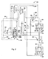
- System 100 is an implement hydraulic system coupled to a tractor hydraulic system 102.
- the implement hydraulic system 100 includes an implement wing cylinder structure 104 shown with two cylinders 106. It should be understood that the wing cylinder structure 104 can have any number of cylinders 106 as desired.
- the implement wing, and the implement wing cylinder structure is configured such that the implement wings are lowered when the cylinder rods 108 are extended. However, the implement could be constructed such that the implement wings are lowered when the rods 108 are retracted.
- the hydraulic connections to the wing cylinder structure will be referred to in the claims as connections to a first end 110 or a second end 112 without regard to whether this is a reference to the cap end or rod end of the cylinders.
- the hydraulic system 100 also includes an implement center frame cylinders structure 114 shown as having two cylinders 116. Again, any number of cylinders 116 may be included in the center frame cylinder structure.
- the implement center frame and center frame cylinder structure are constructed such that the implement is raised when the cylinder rods 118 are extended, and lowered when the rods 118 are retracted. Again, the implement could be structured such that the implement is raised when the rods 118 are retracted, thus the connections to the center frame cylinder structure will be referred to in the claims as connections to the first end or second end without regard to whether this reference is to the cap end or the rod end of the cylinders.
- the first ends 110 and 120 of the wing cylinder structure and the center frame cylinder structure are connected to the SCV in parallel.
- the second ends 112 and 122 of the wing cylinder structure and the center frame cylinder structure are connected to the SCV in parallel.
- the tractor hydraulic system 102 includes a load sense controlled pump 124 that provides flow to a selective control valve (SCV) 126.
- the selective control valve has a neutral position 126N, a first open position 126R used to raise the implement and wings, a second open position 126L used to lower the wings and the implement, and a float position 126F.
- the SCV thus controls the raising and lowering of the implement.
- a pressure reducing/relieving valve 128 regulates the pressure delivered to the second end 112 of the wing cylinder structure 104.
- the pressure reducing/relieving valve 128 has an inlet 130, an outlet 132 and a return check valve 134 that allows flow to bypass the pressure reducing/relieving valve 128 during retraction of the rods 108 of the wing cylinder structure.
- a drain check valve 136 protects the pressure reducing/relieving valve during wing cylinder structure retraction.
- a hydraulic latching function is provided in the circuit by first and second dual-pilot-operated, two-way, two-position, normally-closed directional valves 140, 150.
- the first directional valve 140 is placed in a power beyond supply connection 142 from the pump to the inlet 130 of the pressure reducing/relieving valve 128.
- the second directional valve 150 is located in the power beyond return connection 144 between first end 110 of the wing cylinder structure and the tank 160. These directional valves may be combined into one dual-pilot-operated, four-way, two-position valve.
- a load sense pressure line 146 is provided between the outlet 132 of the valve 128 and the pump 124.
- the system 100 further includes first and second sequence valves 152, 154.
- First sequencing valve 152 is in the parallel connection to the first end 120 of the center frame cylinder structure.
- Second sequencing valve 154 is in the parallel connection to the second end of the wing cylinder structure.
- the first sequence valve 152 prevents the center frame cylinder structure from extending until the sequence valve 152 set pressure is reached. However, oil is allowed to enter the first end 110 of the wing cylinder structure. Oil freely exits the second end of the wing cylinder structure through the return check valve 134. Once the wing cylinder structure is fully retracted, the supply pressure builds until the first sequence valve 152 opens. Then the center frame cylinder structure extends.
- the directional valves remain open until the SCV 126 is actuated to the first open position 126R to raise the implement or if the SCV is moved to the float position 126F.
- pilot pressure provided to the directional valves 140, 150 closes the valves.
- the pilot pressures on the directional valves 140, 150 equalize, allowing the springs to close the directional valves, deactivating the down force circuit. If the directional valves 140, 150 are open during the start of an implement raise cycle, then oil would also flow through the orifice 156 and the second directional valve 150 to the power beyond return. As this oil flow increases, the orifice would cause ample pressure when coupled with the spring force to close the directional valve 150.
- the system 100 provides a sequencing for the desired operation of the center frame cylinder structure and the wing cylinder structure and also provides hydraulic latching to activate down force control on the wing cylinder structure.
- FIG 2 another hydraulic system 200 is shown.
- system 200 is identical to system 100. Similar or identical components are given the same reference numeral beginning with 2 instead of 1.
- System 200 uses the same sequencing as system 100 but it is a different latching circuit.
- latching is accomplished by a normally-open, three-way, two-position, pilot-operated, directional valve 240 and a normally-closed, four-way, two-position, pilot-operated, directional valve 250.
- sequence valve 254 opens which pilots the directional valve 250 open, opening the power beyond supply connection 242 to the pressure reducing/relieving valve 228 to the second end 212 of the wing cylinder structure.
- the hydraulic systems use hydraulic latching to allow a load sense power source to be activated and deactivated by the SCV.
- the load sense power source is activated when the cylinders of the wing cylinder structure are fully extended as shown, or fully retracted.
- the load sense power source remains activated, that is latched, when the SCV is returned to neutral. It is deactivated or unlatched when the cylinders are retracted as shown.
Landscapes
- Life Sciences & Earth Sciences (AREA)
- Soil Sciences (AREA)
- Environmental Sciences (AREA)
- Engineering & Computer Science (AREA)
- Mechanical Engineering (AREA)
- Fluid-Pressure Circuits (AREA)
- Catching Or Destruction (AREA)
- Lifting Devices For Agricultural Implements (AREA)
Claims (10)
- Gerätehydrauliksystem (100, 200) zum Gebrauch mit einem Zugmaschinenhydrauliksystem (102, 202), wobei das Zugmaschinenhydrauliksystem (102, 202) eine lastsensitiv gesteuerte Pumpe (124, 224) und ein Steuerventil (SCV) (126, 226) mit mehreren auswählbaren Positionen aufweist, das eine geschlossene neutrale Position (126N, 226N), eine erste offene Position (126R, 226R) und eine zweite offene Position (126L, 226L) aufweist, wobei das SCV (126, 226) zwischen der Pumpe (124, 224) und dem Gerätehydrauliksystem (100, 200) verbunden werden kann, wobei das Gerätehydrauliksystem (100, 200) eine Geräteflügelzylinderstruktur (104, 204), die erste und zweite Enden (110, 112, 210, 212) aufweist; eine Gerätemittelrahmenzylinderstruktur (114, 214), die erste und zweite Enden (120, 122, 220, 222) aufweist; ein einstellbares Druckventil (128, 228), das einen Eingang (130, 230) und einen Ausgang (132, 232) aufweist und das zwischen dem Auswahl-Steuerventil (126, 226) und dem zweiten Ende (112, 212) der Flügelzylinderstruktur verbunden ist; eine Power-Beyond-Versorgungsverbindung (142, 242) von der Pumpe (124, 224) zu dem Eingang (130, 230) des einstellbaren Druckventils (128, 228), wobei die Power-Beyond-Versorgungsverbindung (142, 242) eine Quelle für unter Druck stehendes Hydraulikfluid für das einstellbare Druckventil (128, 228) unabhängig von dem unter Druck stehenden Hydraulikfluid aus dem Auswahl-Steuerventil (126, 226) zur Verfügung stellt; eine lastsensitive Verbindung (146) von dem Ausgang (132, 232) des einstellbaren Druckventils (128, 228) zu der Pumpe (124, 224) umfasst; dadurch gekennzeichnet, dass es ferner Sperrventilmittel in der Power-Beyond-Versorgungsverbindung (142, 242) zum Öffnen und Schließen der Verbindung (142, 242), wobei die Sperrventilmittel arbeiten, die Verbindung (142, 242) bis nach dem Anwenden des Fluiddrucks von dem Auswahl-Steuerventil (126, 226) auf das zweite Ende (112, 212) der Flügelzylinderstruktur (104, 204) zu schließen, wonach die Ventilmittel die Verbindung (142, 242) öffnen und die Verbindung (142, 242) offen halten, wenn das Auswahl-Steuerventil (126, 226) zur neutralen Position (126N, 226N) zurückgeführt wird; ein erstes Zuschaltventil (152, 252), um Fluid zu dem ersten Ende (110, 210) der Flügelzylinderstruktur (104, 204) und dann zu dem ersten Ende (120, 220) der Mittelrahmenzylinderstruktur (114, 214) zu leiten, wenn das SCV (126, 226) in der ersten offenen Position (126R, 226R) ist; und ein zweites Zuschaltventil (154, 254), um Fluid zu dem ersten Ende (122, 222) der Mittelrahmenzylinderstruktur (114, 214) und dann zu dem zweiten Ende (112, 212) der Flügelzylinderstruktur (104, 204) zu leiten, wenn das SCV (126, 226) in der zweiten offenen Position (126L, 226L) ist, umfasst.
- Gerätehydrauliksystem (100) nach Anspruch 1, das ferner eine Power-Beyond-Rückführungsverbindung (144) zwischen der Pumpe (124) und dem ersten Ende (110) der Flügelzylinderstruktur (104) umfasst, wobei die Sperrventilmittel ein normalerweise geschlossenes erstes Richtungsventil (140) in der Power-Beyond-Verbindung (142) von der Pumpe (124) zu dem Eingang (130) des einstellbaren Druckventils (128), das gesteuert wird, sich zu öffnen, wenn das SCV (126) zu der zweiten offenen Position (126L) bewegt wird, und ein zweites Richtungsventil (150), das in der Power-Beyond-Rückführungsverbindung (144) angeordnet ist, enthalten, wobei das zweite Richtungsventil (150) normalerweise geschlossen ist und gesteuert wird, sich zu öffnen, wenn das SCV (126) in die zweite offne Position (126L) bewegt wird.
- Gerätehydrauliksystem (100) nach Anspruch 2, wobei das erste und zweite Richtungsventil (140, 150) durch den Power-Beyond-Versorgungsdruck weiterhin gesteuert werden, offen zu bleiben, wenn das SCV (126) zu der neutralen Position (126N) zurückgestellt wird.
- Gerätehydrauliksystem (100) nach Anspruch 2 oder 3, wobei das erste und zweite Richtungsventil (140, 150) vorgesteuerte Doppelventile sind, wobei der Steuerdruck zum Schließen der Ventile (140, 150) von dem Systemdruck zugeführt wird, wenn das SCV (126) in der zweiten offenen Position (126L) ist.
- Gerätehydrauliksystem (100) nach einem der Ansprüche 2 bis 4, wobei das erste und zweite Richtungsventil (140, 150) als Vierwege-Auf/Zu-Ventil gebildet sind.
- Gerätehydrauliksystem (200) nach Anspruch 1, wobei die Sperrventilmittel Folgendes enthalten: ein erstes Richtungsventil (240) in der Power-Beyond-Versorgungsverbindung (242), wobei das erste Richtungsventil (240) normalerweise offen ist und zu einer geschlossenen Position bewegt wird, wenn das SCV (226) in die erste offene Position (226R) bewegt wird, und ein normalerweise geschlossenes zweites Richtungsventil (250) in der Power-Beyond-Versorgungsverbindung (242), das zu einer offenen Position bewegt wird, wenn das SCV (226) zu der zweiten offenen Position (226L) bewegt wird.
- Gerätehydrauliksystem (200) nach Anspruch 6, wobei das erste Richtungsventil (240) ein Dreiwege-Auf/Zu-Ventil ist.
- Gerätehydrauliksystem (200) nach Anspruch 6 oder 7, wobei das zweite Richtungsventil (250) ein Vierwege-Auf/Zu-Ventil ist.
- Gerätehydrauliksystem (100, 200) nach einem der Ansprüche 1 bis 8, das ferner parallele Verbindungen von dem SCV (126, 226) zu den ersten Enden (110, 210, 120, 220) der Flügelzylinderstruktur (104, 204) und der Mittelrahmenzylinderstuktur (114, 214) umfasst und wobei sich das erste Zuschaltventil (152, 252) in der parallelen Verbindung zu dem ersten Ende (120, 220) der Mittelrahmenzylinderstuktur (114, 214) befindet.
- Gerätehydrauliksystem (100, 200) nach einem der Ansprüche 1 bis 9, das ferner parallele Verbindungen von dem SCV (126, 226) zu den zweiten Enden (112, 212, 122, 222) der Flügelzylinderstruktur (104, 204) und der Mittelrahmenzylinderstuktur (114, 214) umfasst, wobei sich das zweite Zuschaltventil (154, 254) in der parallelen Verbindung zu dem zweiten Ende (112, 212) der Flügelzylinderstruktur (104, 204) befindet.
Applications Claiming Priority (1)
| Application Number | Priority Date | Filing Date | Title |
|---|---|---|---|
| US12/762,611 US7918285B1 (en) | 2010-04-19 | 2010-04-19 | Implement with active wing down force and wing lift sequencing |
Publications (2)
| Publication Number | Publication Date |
|---|---|
| EP2377383A1 EP2377383A1 (de) | 2011-10-19 |
| EP2377383B1 true EP2377383B1 (de) | 2013-08-07 |
Family
ID=43805791
Family Applications (1)
| Application Number | Title | Priority Date | Filing Date |
|---|---|---|---|
| EP11004135.7A Active EP2377383B1 (de) | 2010-04-19 | 2011-05-19 | Arbeitsgeräte-Hydrauliksystem |
Country Status (8)
| Country | Link |
|---|---|
| US (1) | US7918285B1 (de) |
| EP (1) | EP2377383B1 (de) |
| AR (1) | AR081171A1 (de) |
| AU (1) | AU2011201689B2 (de) |
| BR (1) | BRPI1101737B1 (de) |
| CA (1) | CA2737824C (de) |
| ES (1) | ES2429842T3 (de) |
| UA (1) | UA106477C2 (de) |
Cited By (5)
| Publication number | Priority date | Publication date | Assignee | Title |
|---|---|---|---|---|
| US10045475B2 (en) | 2015-09-23 | 2018-08-14 | Deere & Company | Roller basket finishing attachment |
| US10076072B2 (en) | 2015-09-23 | 2018-09-18 | Deere & Company | Tillage implement with intra-wing gang offset |
| WO2018140986A3 (en) * | 2017-01-25 | 2018-09-27 | General Electric Company | Hydraulic actuator with pressure-based piston position feedback |
| US10194573B2 (en) | 2015-09-23 | 2019-02-05 | Deere & Company | Anti-tangle harrow attachment |
| US10327373B2 (en) | 2015-09-23 | 2019-06-25 | Deere & Company | Harrow downforce adjustment |
Families Citing this family (38)
| Publication number | Priority date | Publication date | Assignee | Title |
|---|---|---|---|---|
| US8056465B2 (en) * | 2008-09-29 | 2011-11-15 | Deere & Company | Active implement down force system providing reduced heat generation |
| US8573111B2 (en) * | 2010-04-19 | 2013-11-05 | Deere & Company | Active implement down force system with automatic latching of tractor power beyond pressure |
| US9232687B2 (en) | 2010-09-15 | 2016-01-12 | Dawn Equipment Company | Agricultural systems |
| US8544397B2 (en) | 2010-09-15 | 2013-10-01 | Dawn Equipment Company | Row unit for agricultural implement |
| US12171152B2 (en) | 2010-09-15 | 2024-12-24 | Deere & Company | System and method for adaptively controlling depth of ground-engaging planting row unit using forward sensor that measures residue ahead of row unit |
| US12389816B2 (en) | 2013-02-04 | 2025-08-19 | Deere & Company | Agricultural systems |
| US9271437B2 (en) | 2011-07-01 | 2016-03-01 | Charles H. Martin | Agricultural field preparation device |
| CA3077136C (en) | 2012-01-25 | 2021-12-07 | Precision Planting Llc | Agricultural toolbar apparatus, systems, and methods |
| WO2014004633A1 (en) * | 2012-06-28 | 2014-01-03 | Kinze Manufacturing, Inc. | Weight distribution system for seed planters and product applicators |
| US9161488B2 (en) * | 2012-09-06 | 2015-10-20 | Cnh Industrial America Llc | Wing lifting system for an agricultural implement |
| US8794344B2 (en) | 2012-09-06 | 2014-08-05 | Cnh Industrial America Llc | Down pressure control system for an agricultural implement |
| US9215839B2 (en) | 2013-02-01 | 2015-12-22 | Dawn Equipment Company | Agricultural apparatus with hybrid single-disk, double-disk coulter arrangement |
| US9609796B2 (en) | 2013-10-17 | 2017-04-04 | Abi Attachments, Inc. | Grading tools for work machines and operation thereof |
| US10721855B2 (en) | 2014-02-05 | 2020-07-28 | Dawn Equipment Company | Agricultural system for field preparation |
| US9668398B2 (en) | 2014-02-05 | 2017-06-06 | Dawn Equipment Company | Agricultural system for field preparation |
| US9615497B2 (en) | 2014-02-21 | 2017-04-11 | Dawn Equipment Company | Modular autonomous farm vehicle |
| US10444774B2 (en) | 2014-11-07 | 2019-10-15 | Dawn Equipment Company | Agricultural system |
| US10582653B2 (en) | 2014-11-07 | 2020-03-10 | Dawn Equipment Company | Agricultural planting system with automatic depth control |
| US9848522B2 (en) | 2014-11-07 | 2017-12-26 | Dawn Equipment Company | Agricultural system |
| US11197411B2 (en) | 2014-11-07 | 2021-12-14 | Dawn Equipment Company | Agricultural planting system with automatic depth control |
| US9723778B2 (en) | 2014-11-07 | 2017-08-08 | Dawn Equipment Company | Agricultural system |
| CN104782258A (zh) * | 2015-04-23 | 2015-07-22 | 山东常林道依茨法尔机械有限公司 | 一种小功率轮式拖拉机强压装置 |
| US10477760B2 (en) | 2015-12-28 | 2019-11-19 | Underground Agriculture, LLC | Agricultural organic device for weed control |
| US10980174B2 (en) | 2015-12-28 | 2021-04-20 | Underground Agriculture, LLC | Agricultural mowing device |
| US11083134B2 (en) | 2015-12-28 | 2021-08-10 | Underground Agriculture, LLC | Agricultural inter-row mowing device |
| US10227998B2 (en) * | 2015-12-31 | 2019-03-12 | Cnh Industrial America Llc | System for controlling the supply of hydraulic fluid to a work vehicle implement |
| WO2017135919A1 (en) * | 2016-02-01 | 2017-08-10 | Halliburton Energy Services, Inc. | Multi-mode hydraulic cylinder control system for hydraulic workover unit |
| US10548260B2 (en) | 2017-05-04 | 2020-02-04 | Dawn Equipment Company | System for automatically setting the set point of a planter automatic down pressure control system with a seed furrow sidewall compaction measurement device |
| US11006563B2 (en) | 2017-05-04 | 2021-05-18 | Dawn Equipment Company | Seed firming device for improving seed to soil contact in a planter furrow with feature designed to prevent the buildup of soil on the outer surfaces by discharging pressurized fluid |
| US10645865B2 (en) | 2017-05-04 | 2020-05-12 | Dawn Equipment Company | Agricultural row unit with automatic control system for furrow closing device |
| US10660257B2 (en) | 2017-10-26 | 2020-05-26 | Cnh Industrial America Llc | System and method for automatically actuating wing assemblies of an agricultural implement |
| US11696523B2 (en) | 2019-01-14 | 2023-07-11 | Cnh Industrial America Llc | System and method for hydraulically leveling a multi-wing agricultural implement |
| US11659782B2 (en) * | 2020-04-02 | 2023-05-30 | Deere & Company | Walking track system of an agricultural implement |
| US11674535B2 (en) | 2020-05-29 | 2023-06-13 | Cnh Industrial America Llc | Hydraulic system having a drain bypass |
| US11377823B1 (en) | 2021-07-28 | 2022-07-05 | Deere & Company | Flow management of a hydraulic system |
| US11378104B1 (en) | 2021-07-28 | 2022-07-05 | Deere & Company | Flow management of a hydraulic system |
| US11378102B1 (en) | 2021-07-28 | 2022-07-05 | Deere & Company | Flow management of a hydraulic system |
| FR3131353B1 (fr) * | 2021-12-23 | 2024-01-26 | Poclain Hydraulics Ind | Architecture hydraulique améliorée pour couplage d’un circuit hydraulique secondaire |
Family Cites Families (13)
| Publication number | Priority date | Publication date | Assignee | Title |
|---|---|---|---|---|
| US4067394A (en) * | 1976-01-22 | 1978-01-10 | White Farm Equipment Company | Implement with automatic sequencing valve and system |
| US4915014A (en) * | 1985-05-08 | 1990-04-10 | Deere & Company | Disk harrow hydraulic wing balancing system |
| US4878545A (en) * | 1987-06-15 | 1989-11-07 | Victory Equipment (1983) Limited | Agricultural implement with foldable wing |
| CA2067081A1 (en) * | 1992-03-24 | 1993-10-25 | Terrance Friggstad | Rockshaft cultivator frame |
| CA2164024C (en) * | 1995-11-29 | 2005-08-16 | James Wayne Henry | Down-pressure system for agricultural implement |
| US6068063A (en) * | 1998-02-27 | 2000-05-30 | Flexi-Coil Ltd. | Hydraulic connection circuit between first and active hydraulic circuits |
| US6035943A (en) * | 1998-05-28 | 2000-03-14 | Flexi-Coil Ltd | Frame leveling system for tillage implements |
| DE19828963A1 (de) * | 1998-06-29 | 1999-12-30 | Mannesmann Rexroth Ag | Hydraulische Schaltung |
| US6318477B1 (en) * | 2000-02-09 | 2001-11-20 | Case Corporation | Toolbar wing lift control |
| US6675907B2 (en) * | 2000-08-10 | 2004-01-13 | Case, Llc | Flexible toolbar and operating hydraulic circuit |
| US6698523B2 (en) * | 2002-07-02 | 2004-03-02 | Husco International, Inc. | Electrohydraulic control system for implement lift cylinders |
| US7478683B2 (en) * | 2005-07-29 | 2009-01-20 | Deere & Company | Cylinder synchronization for an implement lift system |
| US8056465B2 (en) | 2008-09-29 | 2011-11-15 | Deere & Company | Active implement down force system providing reduced heat generation |
-
2010
- 2010-04-19 US US12/762,611 patent/US7918285B1/en active Active
-
2011
- 2011-04-13 AR ARP110101265A patent/AR081171A1/es active IP Right Grant
- 2011-04-14 AU AU2011201689A patent/AU2011201689B2/en active Active
- 2011-04-15 UA UAA201104632A patent/UA106477C2/uk unknown
- 2011-04-18 BR BRPI1101737-6A patent/BRPI1101737B1/pt active IP Right Grant
- 2011-04-19 CA CA2737824A patent/CA2737824C/en active Active
- 2011-05-19 ES ES11004135T patent/ES2429842T3/es active Active
- 2011-05-19 EP EP11004135.7A patent/EP2377383B1/de active Active
Cited By (6)
| Publication number | Priority date | Publication date | Assignee | Title |
|---|---|---|---|---|
| US10045475B2 (en) | 2015-09-23 | 2018-08-14 | Deere & Company | Roller basket finishing attachment |
| US10076072B2 (en) | 2015-09-23 | 2018-09-18 | Deere & Company | Tillage implement with intra-wing gang offset |
| US10149423B2 (en) | 2015-09-23 | 2018-12-11 | Deere & Company | Integrated drawbar for finishing attachments |
| US10194573B2 (en) | 2015-09-23 | 2019-02-05 | Deere & Company | Anti-tangle harrow attachment |
| US10327373B2 (en) | 2015-09-23 | 2019-06-25 | Deere & Company | Harrow downforce adjustment |
| WO2018140986A3 (en) * | 2017-01-25 | 2018-09-27 | General Electric Company | Hydraulic actuator with pressure-based piston position feedback |
Also Published As
| Publication number | Publication date |
|---|---|
| AU2011201689B2 (en) | 2015-09-10 |
| ES2429842T3 (es) | 2013-11-18 |
| CA2737824C (en) | 2017-09-19 |
| UA106477C2 (uk) | 2014-09-10 |
| AR081171A1 (es) | 2012-07-04 |
| BRPI1101737B1 (pt) | 2020-06-16 |
| RU2011113337A (ru) | 2012-10-20 |
| EP2377383A1 (de) | 2011-10-19 |
| BRPI1101737A2 (pt) | 2012-08-21 |
| US7918285B1 (en) | 2011-04-05 |
| CA2737824A1 (en) | 2011-10-19 |
| AU2011201689A1 (en) | 2011-11-03 |
Similar Documents
| Publication | Publication Date | Title |
|---|---|---|
| CA2737824C (en) | Implement with active wing down force and wing lift sequencing | |
| US8573111B2 (en) | Active implement down force system with automatic latching of tractor power beyond pressure | |
| RU2011121591A (ru) | Гидравлическая система с электронным управлением для сельскохозяйственного орудия | |
| US10321621B2 (en) | Electronic latching circuit | |
| EP1766146B2 (de) | Hubwerksventilanordnung | |
| RU2011121699A (ru) | Гидравлическая система с механическим управлением для сельскохозяйственного орудия | |
| EP2955389B1 (de) | Hydraulisches System mit Energierückgewinnung | |
| CN102425582B (zh) | 一种液压控制阀及设有该阀的消防车下车支腿控制系统 | |
| RU2011121593A (ru) | Гидравлический пульт дистанционного управления для гидравлической системы сельскохозяйственного орудия | |
| KR20170069460A (ko) | 작업차용 작업기 승강 및 플로팅 구현을 위한 유압회로 | |
| CN102597538A (zh) | 控制方案 | |
| GB2405673A (en) | Valve arrangement and hydraulic actuator | |
| KR102707689B1 (ko) | 농업용 작업차량의 작업기 승강 및 유압 취출을 위한 유압장치 | |
| CN110550552B (zh) | 调压系统、起重机及调压方法 | |
| CN109854556B (zh) | 油源阀、液压系统和工程机械 | |
| DE102008064136A1 (de) | Hydraulische Steueranordnung | |
| RU2574125C2 (ru) | Орудие с активным прижимным усилием боковины и последовательность поднятия боковины | |
| JPH048903A (ja) | 多機能弁 | |
| CN222229007U (zh) | 一种液压系统 | |
| JPH0451531Y2 (de) | ||
| JP2015218847A (ja) | 油圧シリンダ装置 | |
| CA2897193A1 (en) | Split function valve | |
| JPS5824641Y2 (ja) | 流体制御装置 | |
| JPS58160603A (ja) | 流体制御用バルブ |
Legal Events
| Date | Code | Title | Description |
|---|---|---|---|
| AK | Designated contracting states |
Kind code of ref document: A1 Designated state(s): AL AT BE BG CH CY CZ DE DK EE ES FI FR GB GR HR HU IE IS IT LI LT LU LV MC MK MT NL NO PL PT RO RS SE SI SK SM TR |
|
| AX | Request for extension of the european patent |
Extension state: BA ME |
|
| PUAI | Public reference made under article 153(3) epc to a published international application that has entered the european phase |
Free format text: ORIGINAL CODE: 0009012 |
|
| 17P | Request for examination filed |
Effective date: 20120419 |
|
| RIC1 | Information provided on ipc code assigned before grant |
Ipc: A01B 63/10 20060101AFI20130222BHEP |
|
| GRAP | Despatch of communication of intention to grant a patent |
Free format text: ORIGINAL CODE: EPIDOSNIGR1 |
|
| INTG | Intention to grant announced |
Effective date: 20130411 |
|
| GRAS | Grant fee paid |
Free format text: ORIGINAL CODE: EPIDOSNIGR3 |
|
| GRAA | (expected) grant |
Free format text: ORIGINAL CODE: 0009210 |
|
| AK | Designated contracting states |
Kind code of ref document: B1 Designated state(s): AL AT BE BG CH CY CZ DE DK EE ES FI FR GB GR HR HU IE IS IT LI LT LU LV MC MK MT NL NO PL PT RO RS SE SI SK SM TR |
|
| REG | Reference to a national code |
Ref country code: GB Ref legal event code: FG4D |
|
| REG | Reference to a national code |
Ref country code: AT Ref legal event code: REF Ref document number: 625280 Country of ref document: AT Kind code of ref document: T Effective date: 20130815 Ref country code: CH Ref legal event code: EP |
|
| REG | Reference to a national code |
Ref country code: IE Ref legal event code: FG4D |
|
| REG | Reference to a national code |
Ref country code: DE Ref legal event code: R096 Ref document number: 602011002555 Country of ref document: DE Effective date: 20131002 |
|
| REG | Reference to a national code |
Ref country code: ES Ref legal event code: FG2A Ref document number: 2429842 Country of ref document: ES Kind code of ref document: T3 Effective date: 20131118 |
|
| REG | Reference to a national code |
Ref country code: AT Ref legal event code: MK05 Ref document number: 625280 Country of ref document: AT Kind code of ref document: T Effective date: 20130807 |
|
| REG | Reference to a national code |
Ref country code: NL Ref legal event code: VDEP Effective date: 20130807 |
|
| REG | Reference to a national code |
Ref country code: LT Ref legal event code: MG4D |
|
| PG25 | Lapsed in a contracting state [announced via postgrant information from national office to epo] |
Ref country code: SE Free format text: LAPSE BECAUSE OF FAILURE TO SUBMIT A TRANSLATION OF THE DESCRIPTION OR TO PAY THE FEE WITHIN THE PRESCRIBED TIME-LIMIT Effective date: 20130807 Ref country code: HR Free format text: LAPSE BECAUSE OF FAILURE TO SUBMIT A TRANSLATION OF THE DESCRIPTION OR TO PAY THE FEE WITHIN THE PRESCRIBED TIME-LIMIT Effective date: 20130807 Ref country code: LT Free format text: LAPSE BECAUSE OF FAILURE TO SUBMIT A TRANSLATION OF THE DESCRIPTION OR TO PAY THE FEE WITHIN THE PRESCRIBED TIME-LIMIT Effective date: 20130807 Ref country code: PT Free format text: LAPSE BECAUSE OF FAILURE TO SUBMIT A TRANSLATION OF THE DESCRIPTION OR TO PAY THE FEE WITHIN THE PRESCRIBED TIME-LIMIT Effective date: 20131209 Ref country code: NO Free format text: LAPSE BECAUSE OF FAILURE TO SUBMIT A TRANSLATION OF THE DESCRIPTION OR TO PAY THE FEE WITHIN THE PRESCRIBED TIME-LIMIT Effective date: 20131107 Ref country code: AT Free format text: LAPSE BECAUSE OF FAILURE TO SUBMIT A TRANSLATION OF THE DESCRIPTION OR TO PAY THE FEE WITHIN THE PRESCRIBED TIME-LIMIT Effective date: 20130807 Ref country code: CY Free format text: LAPSE BECAUSE OF FAILURE TO SUBMIT A TRANSLATION OF THE DESCRIPTION OR TO PAY THE FEE WITHIN THE PRESCRIBED TIME-LIMIT Effective date: 20130724 Ref country code: IS Free format text: LAPSE BECAUSE OF FAILURE TO SUBMIT A TRANSLATION OF THE DESCRIPTION OR TO PAY THE FEE WITHIN THE PRESCRIBED TIME-LIMIT Effective date: 20131207 |
|
| PG25 | Lapsed in a contracting state [announced via postgrant information from national office to epo] |
Ref country code: NL Free format text: LAPSE BECAUSE OF FAILURE TO SUBMIT A TRANSLATION OF THE DESCRIPTION OR TO PAY THE FEE WITHIN THE PRESCRIBED TIME-LIMIT Effective date: 20130807 Ref country code: PL Free format text: LAPSE BECAUSE OF FAILURE TO SUBMIT A TRANSLATION OF THE DESCRIPTION OR TO PAY THE FEE WITHIN THE PRESCRIBED TIME-LIMIT Effective date: 20130807 Ref country code: GR Free format text: LAPSE BECAUSE OF FAILURE TO SUBMIT A TRANSLATION OF THE DESCRIPTION OR TO PAY THE FEE WITHIN THE PRESCRIBED TIME-LIMIT Effective date: 20131108 Ref country code: LV Free format text: LAPSE BECAUSE OF FAILURE TO SUBMIT A TRANSLATION OF THE DESCRIPTION OR TO PAY THE FEE WITHIN THE PRESCRIBED TIME-LIMIT Effective date: 20130807 Ref country code: FI Free format text: LAPSE BECAUSE OF FAILURE TO SUBMIT A TRANSLATION OF THE DESCRIPTION OR TO PAY THE FEE WITHIN THE PRESCRIBED TIME-LIMIT Effective date: 20130807 Ref country code: SI Free format text: LAPSE BECAUSE OF FAILURE TO SUBMIT A TRANSLATION OF THE DESCRIPTION OR TO PAY THE FEE WITHIN THE PRESCRIBED TIME-LIMIT Effective date: 20130807 Ref country code: BE Free format text: LAPSE BECAUSE OF FAILURE TO SUBMIT A TRANSLATION OF THE DESCRIPTION OR TO PAY THE FEE WITHIN THE PRESCRIBED TIME-LIMIT Effective date: 20130807 |
|
| PG25 | Lapsed in a contracting state [announced via postgrant information from national office to epo] |
Ref country code: CY Free format text: LAPSE BECAUSE OF FAILURE TO SUBMIT A TRANSLATION OF THE DESCRIPTION OR TO PAY THE FEE WITHIN THE PRESCRIBED TIME-LIMIT Effective date: 20130807 |
|
| PG25 | Lapsed in a contracting state [announced via postgrant information from national office to epo] |
Ref country code: EE Free format text: LAPSE BECAUSE OF FAILURE TO SUBMIT A TRANSLATION OF THE DESCRIPTION OR TO PAY THE FEE WITHIN THE PRESCRIBED TIME-LIMIT Effective date: 20130807 Ref country code: SK Free format text: LAPSE BECAUSE OF FAILURE TO SUBMIT A TRANSLATION OF THE DESCRIPTION OR TO PAY THE FEE WITHIN THE PRESCRIBED TIME-LIMIT Effective date: 20130807 Ref country code: CZ Free format text: LAPSE BECAUSE OF FAILURE TO SUBMIT A TRANSLATION OF THE DESCRIPTION OR TO PAY THE FEE WITHIN THE PRESCRIBED TIME-LIMIT Effective date: 20130807 Ref country code: RO Free format text: LAPSE BECAUSE OF FAILURE TO SUBMIT A TRANSLATION OF THE DESCRIPTION OR TO PAY THE FEE WITHIN THE PRESCRIBED TIME-LIMIT Effective date: 20130807 Ref country code: DK Free format text: LAPSE BECAUSE OF FAILURE TO SUBMIT A TRANSLATION OF THE DESCRIPTION OR TO PAY THE FEE WITHIN THE PRESCRIBED TIME-LIMIT Effective date: 20130807 |
|
| PLBE | No opposition filed within time limit |
Free format text: ORIGINAL CODE: 0009261 |
|
| STAA | Information on the status of an ep patent application or granted ep patent |
Free format text: STATUS: NO OPPOSITION FILED WITHIN TIME LIMIT |
|
| 26N | No opposition filed |
Effective date: 20140508 |
|
| REG | Reference to a national code |
Ref country code: DE Ref legal event code: R097 Ref document number: 602011002555 Country of ref document: DE Effective date: 20140508 |
|
| PGFP | Annual fee paid to national office [announced via postgrant information from national office to epo] |
Ref country code: ES Payment date: 20140526 Year of fee payment: 4 Ref country code: IT Payment date: 20140531 Year of fee payment: 4 |
|
| PGFP | Annual fee paid to national office [announced via postgrant information from national office to epo] |
Ref country code: HU Payment date: 20140507 Year of fee payment: 4 |
|
| REG | Reference to a national code |
Ref country code: HU Ref legal event code: AG4A Ref document number: E020042 Country of ref document: HU |
|
| PG25 | Lapsed in a contracting state [announced via postgrant information from national office to epo] |
Ref country code: LU Free format text: LAPSE BECAUSE OF FAILURE TO SUBMIT A TRANSLATION OF THE DESCRIPTION OR TO PAY THE FEE WITHIN THE PRESCRIBED TIME-LIMIT Effective date: 20140519 |
|
| REG | Reference to a national code |
Ref country code: CH Ref legal event code: PL |
|
| PG25 | Lapsed in a contracting state [announced via postgrant information from national office to epo] |
Ref country code: MC Free format text: LAPSE BECAUSE OF FAILURE TO SUBMIT A TRANSLATION OF THE DESCRIPTION OR TO PAY THE FEE WITHIN THE PRESCRIBED TIME-LIMIT Effective date: 20130807 Ref country code: CH Free format text: LAPSE BECAUSE OF NON-PAYMENT OF DUE FEES Effective date: 20140531 Ref country code: LI Free format text: LAPSE BECAUSE OF NON-PAYMENT OF DUE FEES Effective date: 20140531 |
|
| REG | Reference to a national code |
Ref country code: IE Ref legal event code: MM4A |
|
| PG25 | Lapsed in a contracting state [announced via postgrant information from national office to epo] |
Ref country code: IE Free format text: LAPSE BECAUSE OF NON-PAYMENT OF DUE FEES Effective date: 20140519 |
|
| GBPC | Gb: european patent ceased through non-payment of renewal fee |
Effective date: 20150519 |
|
| PG25 | Lapsed in a contracting state [announced via postgrant information from national office to epo] |
Ref country code: IT Free format text: LAPSE BECAUSE OF NON-PAYMENT OF DUE FEES Effective date: 20150519 |
|
| PG25 | Lapsed in a contracting state [announced via postgrant information from national office to epo] |
Ref country code: MT Free format text: LAPSE BECAUSE OF FAILURE TO SUBMIT A TRANSLATION OF THE DESCRIPTION OR TO PAY THE FEE WITHIN THE PRESCRIBED TIME-LIMIT Effective date: 20130807 |
|
| PG25 | Lapsed in a contracting state [announced via postgrant information from national office to epo] |
Ref country code: GB Free format text: LAPSE BECAUSE OF NON-PAYMENT OF DUE FEES Effective date: 20150519 Ref country code: SM Free format text: LAPSE BECAUSE OF FAILURE TO SUBMIT A TRANSLATION OF THE DESCRIPTION OR TO PAY THE FEE WITHIN THE PRESCRIBED TIME-LIMIT Effective date: 20130807 |
|
| REG | Reference to a national code |
Ref country code: FR Ref legal event code: PLFP Year of fee payment: 6 |
|
| PG25 | Lapsed in a contracting state [announced via postgrant information from national office to epo] |
Ref country code: HU Free format text: LAPSE BECAUSE OF NON-PAYMENT OF DUE FEES Effective date: 20150520 |
|
| REG | Reference to a national code |
Ref country code: ES Ref legal event code: FD2A Effective date: 20160624 |
|
| PG25 | Lapsed in a contracting state [announced via postgrant information from national office to epo] |
Ref country code: RS Free format text: LAPSE BECAUSE OF NON-PAYMENT OF DUE FEES Effective date: 20130807 Ref country code: BG Free format text: LAPSE BECAUSE OF FAILURE TO SUBMIT A TRANSLATION OF THE DESCRIPTION OR TO PAY THE FEE WITHIN THE PRESCRIBED TIME-LIMIT Effective date: 20130807 |
|
| PG25 | Lapsed in a contracting state [announced via postgrant information from national office to epo] |
Ref country code: TR Free format text: LAPSE BECAUSE OF FAILURE TO SUBMIT A TRANSLATION OF THE DESCRIPTION OR TO PAY THE FEE WITHIN THE PRESCRIBED TIME-LIMIT Effective date: 20130807 Ref country code: ES Free format text: LAPSE BECAUSE OF NON-PAYMENT OF DUE FEES Effective date: 20150520 |
|
| REG | Reference to a national code |
Ref country code: FR Ref legal event code: PLFP Year of fee payment: 7 |
|
| REG | Reference to a national code |
Ref country code: FR Ref legal event code: PLFP Year of fee payment: 8 |
|
| PG25 | Lapsed in a contracting state [announced via postgrant information from national office to epo] |
Ref country code: MK Free format text: LAPSE BECAUSE OF FAILURE TO SUBMIT A TRANSLATION OF THE DESCRIPTION OR TO PAY THE FEE WITHIN THE PRESCRIBED TIME-LIMIT Effective date: 20130807 |
|
| PG25 | Lapsed in a contracting state [announced via postgrant information from national office to epo] |
Ref country code: AL Free format text: LAPSE BECAUSE OF FAILURE TO SUBMIT A TRANSLATION OF THE DESCRIPTION OR TO PAY THE FEE WITHIN THE PRESCRIBED TIME-LIMIT Effective date: 20130807 |
|
| PGFP | Annual fee paid to national office [announced via postgrant information from national office to epo] |
Ref country code: DE Payment date: 20250423 Year of fee payment: 15 |
|
| PGFP | Annual fee paid to national office [announced via postgrant information from national office to epo] |
Ref country code: FR Payment date: 20250526 Year of fee payment: 15 |