EP2377426A1 - Table à rallonge - Google Patents
Table à rallonge Download PDFInfo
- Publication number
- EP2377426A1 EP2377426A1 EP11425093A EP11425093A EP2377426A1 EP 2377426 A1 EP2377426 A1 EP 2377426A1 EP 11425093 A EP11425093 A EP 11425093A EP 11425093 A EP11425093 A EP 11425093A EP 2377426 A1 EP2377426 A1 EP 2377426A1
- Authority
- EP
- European Patent Office
- Prior art keywords
- extension
- extensible
- movement
- table according
- movable
- Prior art date
- Legal status (The legal status is an assumption and is not a legal conclusion. Google has not performed a legal analysis and makes no representation as to the accuracy of the status listed.)
- Withdrawn
Links
- 230000007246 mechanism Effects 0.000 claims abstract description 19
- 238000000605 extraction Methods 0.000 claims description 3
- 230000001360 synchronised effect Effects 0.000 claims description 3
- 230000000284 resting effect Effects 0.000 description 2
- 238000004026 adhesive bonding Methods 0.000 description 1
- 230000008034 disappearance Effects 0.000 description 1
- 238000004519 manufacturing process Methods 0.000 description 1
- 238000004904 shortening Methods 0.000 description 1
- 239000000126 substance Substances 0.000 description 1
Images




Classifications
-
- A—HUMAN NECESSITIES
- A47—FURNITURE; DOMESTIC ARTICLES OR APPLIANCES; COFFEE MILLS; SPICE MILLS; SUCTION CLEANERS IN GENERAL
- A47B—TABLES; DESKS; OFFICE FURNITURE; CABINETS; DRAWERS; GENERAL DETAILS OF FURNITURE
- A47B1/00—Extensible tables
- A47B1/08—Extensible tables with extensible frames or with additional legs
-
- A—HUMAN NECESSITIES
- A47—FURNITURE; DOMESTIC ARTICLES OR APPLIANCES; COFFEE MILLS; SPICE MILLS; SUCTION CLEANERS IN GENERAL
- A47B—TABLES; DESKS; OFFICE FURNITURE; CABINETS; DRAWERS; GENERAL DETAILS OF FURNITURE
- A47B1/00—Extensible tables
- A47B1/04—Extensible tables with supplementary leaves or drop leaves arranged at the periphery
- A47B1/05—Extensible tables with supplementary leaves or drop leaves arranged at the periphery the leaves being extensible by drawing-out
-
- A—HUMAN NECESSITIES
- A47—FURNITURE; DOMESTIC ARTICLES OR APPLIANCES; COFFEE MILLS; SPICE MILLS; SUCTION CLEANERS IN GENERAL
- A47B—TABLES; DESKS; OFFICE FURNITURE; CABINETS; DRAWERS; GENERAL DETAILS OF FURNITURE
- A47B1/00—Extensible tables
- A47B1/10—Slide mechanisms
Definitions
- the present invention relates to a piece of furniture and more in particular to an extensible table.
- the present invention relates in particular to improvements to extensible tables of the type comprising a main surface underneath which auxiliary surfaces are placed, which, according to need are extracted and carried to the height of the main surface to increase the useful surface area of the table.
- the object of the invention is to obtain an extensible table of the type described above that is particularly efficient and easy to use, with sturdy and inexpensive extension systems.
- an extensible table comprising: a main surface supported by a support base; a first auxiliary surface and a second auxiliary surface, arranged underneath the main surface when the table is retracted in a condition of minimum extension and coplanar and side by side to the main surface when the table is extended in a condition of maximum extension; a table extension mechanism.
- the extension mechanism comprises two movable supports arranged side by side, each carrying one of the auxiliary surfaces.
- the movable supports are guided on the support base for symmetrically and synchronously moving close and away said first and second auxiliary surfaces one with respect to the other during the table extension and retraction movement.
- Each of the two movable supports comprises a lifting and lowering member of the respective auxiliary surface during the table extension and retraction movement.
- the extension mechanism is simple, sturdy and inexpensive to manufacture, and at the same time allows easy maneuverability in the table extension and retraction movements.
- the two movable supports are substantially coplanar to obtain a configuration of minimum vertical overall dimension of the extension mechanism.
- a linkage is provided for mutual connection of said supports.
- the two movable supports are each constrained to a respective rack; the racks develop parallel to the direction of the extension and retraction movement of the table and mesh with a common toothed wheel.
- the movable supports have an open frame development, with a cross element and two respective longitudinal elements, extending parallel to the direction of the extension and retraction movement.
- the longitudinal elements of one of said movable supports are side by side to the longitudinal elements of the other, allowing the two movable supports to take an arrangement of minimum longitudinal overall dimensions, with the longitudinal elements placed underneath the main table surface.
- the longitudinal elements can be guided on longitudinal beams carried by the support base of the table.
- each longitudinal beam is provided with guiding means on two opposite sides extending along the table extension and retraction direction. The guiding means of each longitudinal beam engage a first longitudinal element of one of the movable supports and a second longitudinal element of the other of the movable supports, so that each movable support is engaged and guided on both of said longitudinal beams.
- each of said lifting and lowering members for the auxiliary surfaces comprises at least one section bar carried by the respective movable support and whereto the respective auxiliary surface is constrained; the section bar has a relative shifting movement with respect to the movable support whereto it is constrained; and during the table extension movement the section bar is locked into a maximum extension position that is reached before the corresponding movable support has reached the maximum extraction position, an overtravel of the movable support with respect to the section bar causing a vertical movement of the section bar and of the auxiliary surface carried thereby, for imposing a shifting movement on said auxiliary surface from a lower position to the height of the main surface.
- this arrangement is double, by providing that each of said lifting and lowering members of the auxiliary surfaces comprises two section bars carried by the respective movable support.
- the table extension and retraction mechanism can be completed with an electrical actuator, or can be controlled manually.
- the latter can be deactivatable, to also allow manual extension.
- the table indicated as a whole with 1, comprises a support base comprising legs for resting on the floor made in any form.
- the base comprises two legs 3A and 3B in the shape of an upside down U, to which a main surface 5 is fastened.
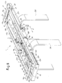
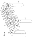
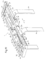
- the surface 5 is mounted through four support columns 7, shown in particular in Figs. 7 and 8 , where the main surface 5 has been removed to show with greater clarity the functional parts of the extensible table 1.
- the columns 7 are mounted two by two on a pair of longitudinal beams 11, 13.
- the longitudinal beams 11 and 13 are fastened to the legs 3A, 3B and form part of the support base of the table 1.
- Each longitudinal beam 11, 13 comprises two substantially vertical and opposite longitudinal sides 11A and 13A.
- guiding means for a pair of movable supports, indicated as a whole with 15 and 17, are positioned on the sides 11A, 13A of the beams 11 and 13.
- the guiding means comprise, for each side 11A, 11A and 13A, 13A of the beams 11 and 13, idle wheels indicated with 11B, 11C for the beam 11 and with 13B, 13C for the beam 13.
- Two longitudinal elements 17A of the movable support 17 engage with the wheels 11B and 13B of the two beams 11 and 13, while corresponding longitudinal elements 15A of the movable support 15 engage with the wheels 11C, 13C.
- Each of the longitudinal elements 15A, 17A has respective guiding grooves 17B, 15B, which form a sort of longitudinal tracks in which the wheels 11B, 13B and 11C, 13C engage.
- Each movable support 15, 17 is completed by a cross element 15C, 17C, so that in substance each movable support 15, 17 has the shape of an open rectangular frame, i.e. an elongated C-shape or U-shape.
- the longitudinal elements 15A, 15A, of the movable support 15 are positioned horizontally side by side to the longitudinal elements 17A, 17A of the movable support 17 and, as can be observed from comparing Figs. 7 and 8 , the arrangement is such that the two frames forming the movable supports 15 and 17 can interpenetrate, to take ( Fig. 7 ) an arrangement of minimum length corresponding to the retracted configuration of the extensible table 1, also shown in Figs. 1 to 3 .
- Respective connecting members 15D and 17D, to which a first and a second auxiliary surface 19, 21 are fastened, are associated with each movable support 15, 17.
- the auxiliary surfaces 19, 21 can be fastened, for example by gluing, to the two connecting members 15D, 15D and 17D, 17D of each movable support 15, 17.
- the connecting members 15D, 15D of the movable support 15 are fastened to a cross member 21 in turn constrained to two longitudinal profiles 23A, 23B connected as described below to the movable support 15.
- the connecting members 17D are fastened to a cross member 25, in turn constrained to two section bars 27A, 27B, connected to the movable support 17.
- Each section bar 23A, 23B and 27A, 27B is fastened to a respective longitudinal element 15A, 15A and 17A, 17A of the first movable support 15 and of the second movable support 17 by means of cross pins 29 that engage in respective inclined slots 31 provided on each of the section bars 23A, 23B and 27A, 27B.
- This arrangement allows a relative shifting movement, according to an inclined direction corresponding to the longitudinal axis of the slots 31, between each section bar 23A, 23B, 27A, 27B and the corresponding longitudinal element 15A, 15A or 17A, 17A of the corresponding movable support 15, 17.
- Each section bar 23A, 23B, 27A, 27B has a roller 33 positioned in proximity of the end of the respective section bar farthest from the cross member 25 or 21.
- Each roller 33 cooperates with a respective shaped stop 35, 37 relative to the support 15 and 39, 41 relative to the movable support 17.
- the shaped stops 35, 37, 39, 41 are rigidly connected to the base formed by the legs 3A, 3B and by the beams 11, 13.
- Each shaped stop 35, 37, 39, 41 has a curved edge with a substantially horizontal portion, a substantially vertical portion and an upside down U-shaped upper curved portion, in which the roller 33 of the respective section bar 23A, 23b, 27A , 27B engages.
- this arrangement allows a relative lifting movement of the connecting members 15D, 17D integral with the section bars 23A, 23B, 27A, 27B when the table is extended, so as to carry the auxiliary surfaces 19, 21 (placed under the main surface 5 when the table is retracted) to a position coplanar with the main surface 5 when the table is in extended position.
- Each of the movable supports 15, 17 is constrained to a bar on which a rack, indicated with 45 for the movable support 15 and with 47 for the movable support 17, is provided.
- the two racks 45, 47 are substantially parallel and develop according to the direction (arrow F) of the extension and retraction movement of the table 1.
- a toothed wheel 49 is provided in an approximately central position of the support base.
- the toothed wheel 49 has a substantially vertical axis of rotation carried by the base of the table, in an intermediate position between the racks 45, 47. These latter are arranged so as to mesh in opposite positions with the toothed wheel 49. In this way the extension and retraction movement according to the double arrow F of the movable supports 15, 17 is synchronous for the two supports.
- the movement according to the arrow F of this support causes a simultaneous and symmetrical movement of the movable support 17 due to meshing of the racks 45, 47 with the toothed wheel 49 which, in this embodiment, is idly supported on the base of the table 1.
- the overtravel of the movable supports 15, 17 with respect to the section bars 23A, 23B and 27A, 27B causes sliding of the pins 29 along the slots 31 and consequent lifting, without further horizontal movement, of the section bars 23A, 23B and 27A, 27B.
- the lifting movement is simultaneous for the two pairs of section bars as a result of the connection mechanism defined by the racks 47, 45 and by the toothed wheel 49. This lifting movement causes lifting of the auxiliary surfaces 19, 21 from the lower position, underneath the main surface 5, to the height of this latter ( Figs. 4 and 6 ).
- the position of the shaped stops 35, 37, 39, 41 is such that the lifting movement of the auxiliary surfaces 19, 21 takes place when these are outside the overall dimensions of the main surface 5 and substantially in exact correspondence with the cross edges thereof, so that in the extended arrangement a single support surface, defined by the auxiliary surfaces 19, 21 and by the main surface 5, is formed ( Fig. 4 ) with the smallest possible space between each auxiliary surface 19, 21 and the main surface 5.
- the shortening, i.e. retraction, movement of the table takes place in reverse, simply by pushing one or the other of the two movable supports 15, 17 toward the base 3A, 3B, 11, 13.
- This movement initially causes lowering of the auxiliary surfaces 19, 21 underneath the level of the main surface 5 and subsequently disappearance of the surfaces 19, 21 underneath the main surface 5 with approach and interpenetration of the U-shaped frames forming the movable supports 15, 17.
- Figs. 9 to 14 differs from the embodiment described above due to the use of an electrical actuator that can be used to carry out the table extension and retraction movement.
- the same numbers indicate in Figs. 9 to 14 parts that are the same as or equivalent to those of Figs. 1 to 8 . Only the additional components with respect to those described with reference to the previous embodiment shall be described below.
- the toothed wheel 49 meshes with a pinion 61 motorized by means of an electrical actuator 63, for example powered by a battery on board the table (not shown) and controlled with a remote control (also not shown) or by means of control members on board the table.
- the actuator 63 is mounted on a plate 65 provided with slots 67 by means of which the plate 65 is connected to the table base. This allows a movement according to the arrow f65 of the plate 65 and consequently of the actuator 63 with its pinion 61 with respect to the toothed wheel 49 which, vice versa, is mounted with its axis fixed relative to the table base 1.
- Figs. 11 and 12 show two positions that the plate 65 and consequently the actuator 63 and motorized pinion 61 can take with respect to the toothed wheel 49.
- the pinion 61 meshes with the wheel 49
- the pinion 61 has been moved to a released position relative to the toothed wheel 49. Consequently, in the arrangement of Fig. 12 the table can be extended with a manual maneuver as described above with reference to the embodiment of Figs. 1 to 8 , for example in the case of a fault of the electrical actuator 63 or depletion of the power batteries.
- Fig. 11 show two positions that the plate 65 and consequently the actuator 63 and motorized pinion 61 can take with respect to the toothed wheel 49.
- the pinion 61 meshes with the wheel 49
- the pinion 61 has been moved to a released position relative to the toothed wheel 49. Consequently, in the arrangement of Fig. 12 the table can be extended with a manual maneuver as described above with reference to the embodiment of Figs. 1 to
- the table extension and retraction movements can be obtained by operation of the electrical actuator 63 which by means of the pinion 61 carries in rotation the toothed wheel 49 and consequently causes shifting in opposite directions (with synchronous and symmetrical movement of the two racks 45, 47) of the moving supports 15 and 17.
- the plate 65 is fastened by means of the slots 67 to a base plate 68 on which the shaped stops 35, 37, 39 and 41 are also fastened.
- the base plate 68 is advantageously fastened to the table legs 3A and 3B and forms an integral part of the fixed support base, relative to which the two moving supports 15, 17 are made to shift in the table extension and retraction movement.
- a mechanism with an eccentric 71 and a lever 73 can be provided, shown in particular in Figs. 11 and 12 .
- the mechanism 71, 73 can be operated to carry the device to the arrangement of Fig. 12 for example when the electrical actuator 63 is broken or when its battery is depleted, or for any other reason, when wishing to carry out table extension or retraction with a manual operation.
- the configuration of the plate 65 and the actuator 63 with the respective pinion 61 is such that this unit can be applied to a table 1 with very simple operations that allow, for example, a manually operated table 1 to be completed with a motorized unit also extemporaneously.
- Figs. 15, 16 and 17, 18 respectively show, in retracted and extended arrangement, another table according to the invention that differs from the previous embodiments due to the shape of the base, which in this case has a single column 3 with a base 3C for resting on the floor.
- the remaining components can be made as described with reference to Figs. 1 to 15 .
Landscapes
- Accommodation For Nursing Or Treatment Tables (AREA)
- Invalid Beds And Related Equipment (AREA)
- Forklifts And Lifting Vehicles (AREA)
- Ladders (AREA)
Applications Claiming Priority (1)
| Application Number | Priority Date | Filing Date | Title |
|---|---|---|---|
| ITFI2010A000066A IT1399460B1 (it) | 2010-04-13 | 2010-04-13 | Tavolo allungabile. |
Publications (1)
| Publication Number | Publication Date |
|---|---|
| EP2377426A1 true EP2377426A1 (fr) | 2011-10-19 |
Family
ID=42985199
Family Applications (1)
| Application Number | Title | Priority Date | Filing Date |
|---|---|---|---|
| EP11425093A Withdrawn EP2377426A1 (fr) | 2010-04-13 | 2011-04-08 | Table à rallonge |
Country Status (4)
| Country | Link |
|---|---|
| US (1) | US8365678B2 (fr) |
| EP (1) | EP2377426A1 (fr) |
| CN (1) | CN102217838A (fr) |
| IT (1) | IT1399460B1 (fr) |
Cited By (3)
| Publication number | Priority date | Publication date | Assignee | Title |
|---|---|---|---|---|
| IT201900000537A1 (it) * | 2019-01-14 | 2020-07-14 | Vetraria Biancadese Di Lucatello & C Sas | Tavolo estensibile |
| IT202200005585A1 (it) * | 2022-03-22 | 2023-09-22 | Calligaris Spa | Tavolo allungabile e relativo procedimento |
| RU229464U1 (ru) * | 2024-09-04 | 2024-10-08 | Общество с ограниченной ответственностью "ЛИСТВИГ РУС" | Стол трансформируемый |
Families Citing this family (21)
| Publication number | Priority date | Publication date | Assignee | Title |
|---|---|---|---|---|
| US8997660B2 (en) * | 2012-03-23 | 2015-04-07 | Johnny A. Satterfield | Deployable table assembly |
| US20130269574A1 (en) * | 2012-04-11 | 2013-10-17 | Christopher Cooper | Expandable and collapsible tables and related methods |
| USD812943S1 (en) | 2016-04-25 | 2018-03-20 | Star International Furniture, Inc. | Table |
| US9675169B1 (en) * | 2016-05-09 | 2017-06-13 | Fang-Hoang Lai | Extendable table |
| CN106881959A (zh) * | 2017-03-03 | 2017-06-23 | 佛山市佛大华康科技有限公司 | 激光蚀刻工作台 |
| CN106983281A (zh) * | 2017-05-05 | 2017-07-28 | 刘凯 | 一种全自动电脑桌运行系统 |
| US10442537B2 (en) | 2017-07-20 | 2019-10-15 | Johnny A. Satterfield | Deployable table assembly |
| IT201700088040A1 (it) * | 2017-07-31 | 2019-01-31 | Calligaris Spa | Tavolo allungabile e metodo connesso |
| US10602656B2 (en) * | 2017-08-04 | 2020-03-31 | Deere & Company | Skip compensation system |
| CN108078155A (zh) * | 2017-12-03 | 2018-05-29 | 徐健华 | 拉伸桌 |
| US10492598B2 (en) | 2018-04-18 | 2019-12-03 | Hadida Worldwide Company, Llc. | Motorized extendable table |
| CN108396413A (zh) * | 2018-05-08 | 2018-08-14 | 浙江开创智库科技有限公司 | 一种纺织机用机架 |
| CN109128971A (zh) * | 2018-09-12 | 2019-01-04 | 刘道灵 | 一种基于铝材生产的智能设备 |
| MX2021013032A (es) * | 2019-04-25 | 2022-02-10 | Ergotron Inc | Estaciones de trabajo de altura ajustable con cero energia inactiva. |
| CN110405228B (zh) * | 2019-06-26 | 2020-12-08 | 泉州台商投资区海雅达新材料有限公司 | 一种窄间距多轴工位隐拓的轴类立式多主轴数控车床 |
| US11974517B2 (en) | 2019-10-31 | 2024-05-07 | Deere & Company | Agricultural seed detection and tracking system |
| US11602095B2 (en) | 2019-10-31 | 2023-03-14 | Deere & Company | Precision agricultural seed delivery system |
| US11425855B2 (en) | 2019-10-31 | 2022-08-30 | Deere & Company | Agricultural seed delivery system using target location map |
| IT202000001621A1 (it) * | 2020-01-28 | 2021-07-28 | B 4 Living Spa | Tavolo allungabile. |
| US11937531B2 (en) | 2020-06-08 | 2024-03-26 | Deere & Company | Systems and methods for selective material placement |
| CN112739108A (zh) * | 2020-12-28 | 2021-04-30 | 巢湖市金辉自控设备有限公司 | 一种壁挂式变频器辅助安装设备 |
Citations (5)
| Publication number | Priority date | Publication date | Assignee | Title |
|---|---|---|---|---|
| FR1272586A (fr) * | 1960-08-13 | 1961-09-29 | Table perfectionnée, avec rallonges à mise en place automatique | |
| DE3603614A1 (de) * | 1986-02-06 | 1987-08-13 | Reinhard Hoernlein | Ausziehtisch |
| DE102004053941B3 (de) * | 2004-11-09 | 2006-02-02 | Inform Gmbh Entwicklung Und Konstruktion | Ausziehtisch |
| US20060032415A1 (en) * | 2004-08-11 | 2006-02-16 | Ming-Cheng Wang | Slide assembly for extension table |
| EP1815767A2 (fr) * | 2006-02-06 | 2007-08-08 | Jean Pierre Brice | Table à rallonges et à mécanisme d'entrainement motorisé des rallonges |
Family Cites Families (13)
| Publication number | Priority date | Publication date | Assignee | Title |
|---|---|---|---|---|
| US1639510A (en) * | 1924-02-09 | 1927-08-16 | Kruger Richard | Extension table |
| US1772629A (en) * | 1929-09-16 | 1930-08-12 | Goldberg Joseph | Extension table |
| US1994538A (en) * | 1933-06-02 | 1935-03-19 | Segal Irving | Extension table |
| US1973894A (en) * | 1933-06-12 | 1934-09-18 | Duncan William Andrew | Extension table |
| US2111616A (en) * | 1934-10-18 | 1938-03-22 | Jr Charles L Creech | Refectory table |
| US2187133A (en) * | 1938-04-09 | 1940-01-16 | Valentine C Luppert | Extension table |
| US2240551A (en) * | 1939-10-14 | 1941-05-06 | Cooper Joseph | Table |
| US2456835A (en) * | 1944-07-31 | 1948-12-21 | American Fixture & Mfg Co | Refectory table |
| US4553485A (en) * | 1982-11-08 | 1985-11-19 | Lee Chain Hsiang | Extension table with single leg |
| US4794869A (en) * | 1988-02-01 | 1989-01-03 | Jack Chiu | Structure of extendable tables |
| US5806437A (en) * | 1997-05-12 | 1998-09-15 | Latitude Tree Furniture Sdn. Bhd. | Table with multiple folding segments |
| US20070289505A1 (en) * | 2006-06-16 | 2007-12-20 | Ronald Roland Turenne | Novel enhanced table leaf mechanism and related methods |
| US8100063B2 (en) * | 2008-02-05 | 2012-01-24 | David O Meyers | Surface expansion mechanism |
-
2010
- 2010-04-13 IT ITFI2010A000066A patent/IT1399460B1/it active
-
2011
- 2011-04-08 EP EP11425093A patent/EP2377426A1/fr not_active Withdrawn
- 2011-04-08 US US13/082,632 patent/US8365678B2/en not_active Expired - Fee Related
- 2011-04-12 CN CN2011100902721A patent/CN102217838A/zh active Pending
Patent Citations (5)
| Publication number | Priority date | Publication date | Assignee | Title |
|---|---|---|---|---|
| FR1272586A (fr) * | 1960-08-13 | 1961-09-29 | Table perfectionnée, avec rallonges à mise en place automatique | |
| DE3603614A1 (de) * | 1986-02-06 | 1987-08-13 | Reinhard Hoernlein | Ausziehtisch |
| US20060032415A1 (en) * | 2004-08-11 | 2006-02-16 | Ming-Cheng Wang | Slide assembly for extension table |
| DE102004053941B3 (de) * | 2004-11-09 | 2006-02-02 | Inform Gmbh Entwicklung Und Konstruktion | Ausziehtisch |
| EP1815767A2 (fr) * | 2006-02-06 | 2007-08-08 | Jean Pierre Brice | Table à rallonges et à mécanisme d'entrainement motorisé des rallonges |
Cited By (4)
| Publication number | Priority date | Publication date | Assignee | Title |
|---|---|---|---|---|
| IT201900000537A1 (it) * | 2019-01-14 | 2020-07-14 | Vetraria Biancadese Di Lucatello & C Sas | Tavolo estensibile |
| IT202200005585A1 (it) * | 2022-03-22 | 2023-09-22 | Calligaris Spa | Tavolo allungabile e relativo procedimento |
| WO2023181083A1 (fr) * | 2022-03-22 | 2023-09-28 | Calligaris S.P.A. | Table extensible et procédé correspondant |
| RU229464U1 (ru) * | 2024-09-04 | 2024-10-08 | Общество с ограниченной ответственностью "ЛИСТВИГ РУС" | Стол трансформируемый |
Also Published As
| Publication number | Publication date |
|---|---|
| US8365678B2 (en) | 2013-02-05 |
| IT1399460B1 (it) | 2013-04-19 |
| CN102217838A (zh) | 2011-10-19 |
| US20110247529A1 (en) | 2011-10-13 |
| ITFI20100066A1 (it) | 2011-10-14 |
Similar Documents
| Publication | Publication Date | Title |
|---|---|---|
| EP2377426A1 (fr) | Table à rallonge | |
| US10835055B2 (en) | Foldable play yard | |
| EP2957190B1 (fr) | Dispositif repose-pied pour fauteuils ou canapés | |
| CN104466772B (zh) | 一种带有位置传感器的抽屉式电力控制柜组件 | |
| US1736108A (en) | Guide suspension for drawers and other movable elements | |
| CN101208028A (zh) | 用于橱柜的支撑拉出式旋转搁架的改进型框架 | |
| CN111820609B (zh) | 一种折叠放置课桌 | |
| KR20140003301A (ko) | 의료용 침대의 등판작동시스템 | |
| CN107713356B (zh) | 一种可翻转伸缩餐台 | |
| JP2019141332A (ja) | 書籍前揃え装置 | |
| CN111012122B (zh) | 一种宽度和高度独立电动控制的仓储货架 | |
| US3049723A (en) | Convertible bed | |
| US3028607A (en) | Sofa bed | |
| CN105380450A (zh) | 一种调节式床架 | |
| US2933113A (en) | Combo-trolley-bench | |
| EP2229074B1 (fr) | Table à rallonge dotée d'un mécanisme de rallonge amélioré | |
| CN212066354U (zh) | 一种床垫收纳装置及系统 | |
| CN207436866U (zh) | 一种新型卷帘门柜结构 | |
| US2964373A (en) | Drawer slide | |
| CN203524297U (zh) | 推拉式地毯展架 | |
| US1881476A (en) | Posting tray | |
| CN207855349U (zh) | 一种可伸缩货架及货物存放系统 | |
| CN209202282U (zh) | 一种具有防打翻功能的折叠桌 | |
| CN206852368U (zh) | 一种可拆卸升降式电动书架 | |
| US844616A (en) | Extension-table. |
Legal Events
| Date | Code | Title | Description |
|---|---|---|---|
| AK | Designated contracting states |
Kind code of ref document: A1 Designated state(s): AL AT BE BG CH CY CZ DE DK EE ES FI FR GB GR HR HU IE IS IT LI LT LU LV MC MK MT NL NO PL PT RO RS SE SI SK SM TR |
|
| AX | Request for extension of the european patent |
Extension state: BA ME |
|
| PUAI | Public reference made under article 153(3) epc to a published international application that has entered the european phase |
Free format text: ORIGINAL CODE: 0009012 |
|
| 17P | Request for examination filed |
Effective date: 20120418 |
|
| 17Q | First examination report despatched |
Effective date: 20130826 |
|
| STAA | Information on the status of an ep patent application or granted ep patent |
Free format text: STATUS: THE APPLICATION IS DEEMED TO BE WITHDRAWN |
|
| 18D | Application deemed to be withdrawn |
Effective date: 20151103 |