EP2377604A1 - Dispositif de mélange destiné au mélange de produit de mélange intégré en gerbes ainsi que procédé de fonctionnement d'un dispositif de mélange - Google Patents
Dispositif de mélange destiné au mélange de produit de mélange intégré en gerbes ainsi que procédé de fonctionnement d'un dispositif de mélange Download PDFInfo
- Publication number
- EP2377604A1 EP2377604A1 EP10004033A EP10004033A EP2377604A1 EP 2377604 A1 EP2377604 A1 EP 2377604A1 EP 10004033 A EP10004033 A EP 10004033A EP 10004033 A EP10004033 A EP 10004033A EP 2377604 A1 EP2377604 A1 EP 2377604A1
- Authority
- EP
- European Patent Office
- Prior art keywords
- crankshaft
- additional mass
- mixing
- mixing device
- mass
- Prior art date
- Legal status (The legal status is an assumption and is not a legal conclusion. Google has not performed a legal analysis and makes no representation as to the accuracy of the status listed.)
- Granted
Links
Images
Classifications
-
- B—PERFORMING OPERATIONS; TRANSPORTING
- B06—GENERATING OR TRANSMITTING MECHANICAL VIBRATIONS IN GENERAL
- B06B—METHODS OR APPARATUS FOR GENERATING OR TRANSMITTING MECHANICAL VIBRATIONS OF INFRASONIC, SONIC, OR ULTRASONIC FREQUENCY, e.g. FOR PERFORMING MECHANICAL WORK IN GENERAL
- B06B1/00—Methods or apparatus for generating mechanical vibrations of infrasonic, sonic, or ultrasonic frequency
- B06B1/10—Methods or apparatus for generating mechanical vibrations of infrasonic, sonic, or ultrasonic frequency making use of mechanical energy
- B06B1/16—Methods or apparatus for generating mechanical vibrations of infrasonic, sonic, or ultrasonic frequency making use of mechanical energy operating with systems involving rotary unbalanced masses
- B06B1/161—Adjustable systems, i.e. where amplitude or direction of frequency of vibration can be varied
- B06B1/162—Making use of masses with adjustable amount of eccentricity
- B06B1/164—Making use of masses with adjustable amount of eccentricity the amount of eccentricity being automatically variable as a function of the running condition, e.g. speed, direction
-
- B—PERFORMING OPERATIONS; TRANSPORTING
- B01—PHYSICAL OR CHEMICAL PROCESSES OR APPARATUS IN GENERAL
- B01F—MIXING, e.g. DISSOLVING, EMULSIFYING OR DISPERSING
- B01F31/00—Mixers with shaking, oscillating, or vibrating mechanisms
- B01F31/20—Mixing the contents of independent containers, e.g. test tubes
- B01F31/265—Mixing the contents of independent containers, e.g. test tubes the vibrations being caused by an unbalanced rotating member
-
- B—PERFORMING OPERATIONS; TRANSPORTING
- B01—PHYSICAL OR CHEMICAL PROCESSES OR APPARATUS IN GENERAL
- B01F—MIXING, e.g. DISSOLVING, EMULSIFYING OR DISPERSING
- B01F35/00—Accessories for mixers; Auxiliary operations or auxiliary devices; Parts or details of general application
- B01F35/40—Mounting or supporting mixing devices or receptacles; Clamping or holding arrangements therefor
- B01F35/42—Clamping or holding arrangements for mounting receptacles on mixing devices
- B01F35/423—Clamping or holding arrangements for mounting receptacles on mixing devices of the vertically movable, two-plates type
Definitions
- the invention relates to a mixing device for mixing mixed material received in containers according to the preamble of claim 1 and to a method for operating a mixing device according to the preamble of claim 15.
- a fundamentally different mixing method is to clamp a closed container with mixed material, for example with pre-dosed formulations, into a mixing device and to move the container as a whole. These container movements are transferred to the mixed material in the container, which ultimately leads to a mixture and homogenization of the mixed material.
- a clamped between turntables closed container in large-scale rotational and / or tumbling movements, for example, with so-called biaxial mixers.
- closed container with material contained therein by means of so-called vibratory mixer in relative short-stroke vibrations, which are transferred to the mix and cause homogenizing currents there.
- This mixing device has a stable housing, in which by means of elastic bearings a swing frame is mounted.
- an eccentric drive is arranged, which is constructed of an electric drive motor and a crankshaft used as an eccentric and driven by a drive belt. Both the drive shaft of the drive motor and the crankshaft are approximately parallel and are horizontal in the mixing device.
- a mixing frame is added, which is coupled in the lower part of the eccentric drive and in the upper part by means of a rocker arm with the swing frame.
- the mixing frame can be forcibly excited by means of the eccentric drive.
- the mixing frame contains a tensioning device which is constructed from two opposite, guided and approximately vertically adjustable clamping plates. Between the two clamping plates, a closed container can be clamped. When the eccentric drive is actuated, the mixing frame is forced to vibrate in ellipsoidal paths in the area of the container used.
- a mixing device for mixing mixed material received in containers which has a holding device for receiving and holding at least one container, further comprising a crankshaft as an eccentric exhibiting eccentric, by means of which the holding device and thus a recorded in this and held container in a defined oscillation and / or vibration movement can be set as a mixing movement.
- the crankshaft is provided with at least one speed-dependent variable and / or speed-dependent displaceable relative to the crankshaft additional mass, preferably starting from an additional mass-base position at standstill of the crankshaft, with increasing speed of the crankshaft so displaced or changeable that one in a defined dimensions increasing, the mixing movement of the holding device causing imbalance is provided.
- the construction of a mixing device can be considerably simplified and can be dispensed with, for example, compared to a mixing device of the prior art to the use of an additional swing frame.
- the structure as a whole is less component-intensive and thus cheaper, and also costs in terms of manufacturing can be advantageously saved.
- the reduction of the components further leads to a reduction of bearings, which increases the life of the device as a whole.
- a simplified and optimized mixing device is provided, in which the desired mixing movement takes place in a structurally relatively simple manner by a speed-dependent change or displacement of a directly or indirectly coupled to the crankshaft additional mass.
- the at least one additional mass is not such a balancing weight which serves as a balancing mass to eliminate imbalances, but rather a specifically desired unbalance, which is additionally provided as a function of speed, for example steadily increasing. to create the desired mixing movement. It is understood that the "growth" of the imbalance in dependence on the speed of the crankshaft can of course be limited, so for example by stops, which will be explained in more detail below.
- the at least one additional mass is preferably designed and / or arranged so that it provides a decreasing imbalance with decreasing speed of the crankshaft until the imbalance of the additional mass basic position is achieved at standstill of the crankshaft.
- that means that the speed-dependent provision of the imbalance is advantageously reversible automatically with decreasing speed.
- the speed-dependent change or displacement of the at least one additional mass means in particular that when the crankshaft is driven in a certain direction of rotation, the at least one additional mass is caused by centrifugal force in a position assigned to a specific rotational speed emigrated or relocated.
- This centrifugal force induced change or displacement of the additional mass can basically be done in different ways.
- This change or displacement of the additional mass can be accomplished in a particularly simple and reliable manner by elastically biasing the at least one additional mass in the additional mass basic position with the crankshaft essentially stationary by means of at least one energy accumulator, wherein the prestressing force of the at least one Force accumulator is set so that the at least one additional mass at a defined speed of the crankshaft (limit speed for displacement) against the biasing force of the energy storage in a defined extent is displaced.
- the displacement path of the at least one additional mass is limited in at least one direction by a stop element, so that the at least one additional mass in the additional mass Basic position is pressed at substantially stationary crankshaft against the stop element and / or that from a defined speed of the crankshaft, the at least one additional mass comes to rest on the stop element.
- a stop element is preferably formed by, for example, a rubber buffer or the like, which allows a rattle-free and therefore substantially noiseless and possibly softly sprung stop.
- the stop element is designed in several parts and on the crankshaft two spaced apart first crankshaft-side stop elements, which cooperate with a second, additional mass side counter element and limit the displacement path.
- the first crankshaft side stop elements are spaced apart from each other by 180 °, so that a relatively large displacement path is provided, which optimized for the desired mixing movements speed-dependent displacement of the at least one additional mass over a relatively large Adjustment range allows.
- the at least one additional mass is supported radially and pivotally mounted on the crankshaft and / or stored.
- the at least one additional mass can grasp the crankshaft body in a form-fitting manner at least in regions and / or be guided there in grooves.
- the additional mass is formed in several parts and a plurality by means of at least one energy storage resiliently clamped against each other mass parts, so that the at least one energy storage holds the mass parts at a standstill of the crankshaft in the additional mass basic position and at least one of Mass parts, preferably all mass parts, are displaced from a defined speed of the crankshaft against the biasing force of the at least one force accumulator.
- the structural complexity can be significantly reduced overall, in which, for example, according to a preferred embodiment, the mass parts are seen in the crankshaft longitudinal direction arranged one behind the other and, for example, by means of a single force accumulator, which is arranged between these mass parts, are urged into the desired position.
- a concrete embodiment is advantageous in which the at least one energy storage the mass parts in the additional mass basic position clamped against each other at substantially stationary crankshaft in such a way that the mass parts with respect to the crankshaft unbalance in a defined extent, preferably substantially completely neutralize, while the mutually strained mass parts with increasing speed of the crankshaft against the force of at least one energy storage so away from each other, that the targeted unbalance of the crankshaft is increased in dependence on the rotational speed and / or the displacement path.
- the mass parts are offset in terms of their imbalance masses in the additional mass base position with substantially stationary crankshaft against each other such that they neutralize substantially, that is whose center of gravity is shifted towards mutual neutralization.
- the individual mass parts can then move out of the additional mass base position in such a way that the unbalance masses of the mass parts which produce the actual unbalance are more or less superimposed to a defined extent and thus form a targeted unbalance on the crankshaft.
- two mass parts are provided according to a preferred specific embodiment of the present invention idea, which are braced against each other by means of at least partially guided around the crankshaft spiral spring as an energy store against each other, wherein the coil spring with one of their spiral spring ends on one of the two Attacks mass parts and this urges or biasing at a standstill crankshaft in the respective additional mass base position.
- the mass parts here may have a T-shaped or mushroom-like outer contour and preferably be mounted in the region of the T-longitudinal web on the crankshaft.
- the coil spring engages with their spiral spring ends on the respective mass part in a transition region between T-longitudinal web and T-crosspiece. Attacking in such a transition region simply represents a defined point of attack that reliably ensures steady attack at the same location.
- the eccentric drive itself is preferably part of the holding device, so that it is necessary to produce the defined, desired mixing movement that the holding device is movably mounted and / or supported in order to perform the desired oscillatory and / or vibrational movements.
- the holding device is so movably supported and / or supported by means of at least one bearing device on a holding device at least partially receiving housing of the mixing device, that the holding device performs a defined mixing movement relative to the housing in the mixing operation.
- the bearing device is formed by a plurality of spaced apart on the holding device acting, causing a resilient suspension supports, which are formed for example by a spring-elastic suspension causing telescopic supports and / or spring damper.
- a particularly stable and functionally reliable support of the holding device can be achieved together with eccentric drive in a table leg-like manner.
- the supports can be stored with their free support ends each additionally in a housing-side elastomeric bearing.
- the holding device itself has a clamping device in the mounted state in approximately vertically opposite clamping plates, of which at least one is adjustable in the vertical direction for clamping receiving a container between the clamping plates.
- a clamping device By means of such a clamping device, the container can be arranged reliably in a simple manner in the mixing device for a mixed operation.
- the eccentric drive is supported on one of the two clamping plates, in particular on a, relative to the mounted position, lower clamping plate of the holding device and / or stored.
- This lower area can be particularly easily and advantageously encapsulated with a housing of the mixing device, so that this eccentric drive for normal mixing operation is not accessible.
- the eccentric drive itself is preferably designed such that it has an electric drive motor which drives the crankshaft directly or indirectly by means of a drive belt.
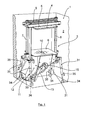
- FIG. 1 schematically and perspectively a view of an exemplary embodiment of a mixing device 1 according to the invention is shown, which is basically taken in a housing 2, which is here, however, partially cut free for reasons of clarity.
- This housing 2 is stable, for example, on a floor, not shown here.
- the mixing device 1 has a holding device 3 for receiving and holding a container, not shown here, which is jammed in a clamping device 4 of the holding device 3.
- the clamping device 4 of the holding device 3 two approximately vertically opposite clamping plate 5, 6, of which the upper clamping plate 5 along the only extremely schematically illustrated threaded spindles 7, 8, driven according to a here also only very schematically and exemplified spindle drive 9 down in Towards a Aufstands Society 10 for the container forming lower clamping plate 6 is shifted.
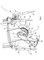
- an eccentric drive 11 is arranged on the holding device 3 in the region below the lower clamping plate 6, which has an electric drive motor 12 which drives a crankshaft 14 by means of a drive belt 13.
- the drive shaft rotatably coupled to the free shaft end 15 of the crankshaft 14 to which the drive belt 13 is guided, not shown for reasons of clarity. It is insofar conventional design.
- crankshaft 14 forms the eccentric of the eccentric drive 11.
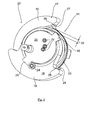
- the two mass parts 16, 17 attached from opposite sides of the crankshaft 14 forth on this and then fixed the end face by means of a face plate 20 by, for example, a plurality of screw 21, which are shown here only extremely schematically, without their radial pivoting relative to the crankshaft 14 to affect.
- the two mass parts 16, 17 are selectively spaced from one another in the longitudinal direction of the crankshaft and have a gap spacing 22.
- a spiral spring 23 is guided around the crankshaft 14 with at least one loop around, in such a way led around that acting as an elastic energy storage coil spring 23, the mass parts 16, 17 with the rubber buffer stops 24, of which in the Fig. 3 only that of the mass portion 16 can be seen presses into abutment against an end plate-side stop element 25.
- the spiral spring 23 engages with its angled spiral spring ends 26, 27 in each case in a transition region 28 of the mass parts 16, 17, which transition region 28 is formed between a crankshaft side shaft region and the actual imbalance mass 18, 19.
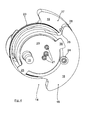
- the biasing force of the example here acting as a force accumulator coil spring 23 is here designed so that in the mixed operation in driven by the drive motor 12 crankshaft 14 from a defined and predetermined depending on predetermined mixing parameters crankshaft speed, the mass parts 16, 17 of the in the Fig. 3 wegverlagern shown at idle crankshaft 14 basic position 29 and speed-dependent or centrifugal force example in a in the Fig. 4 shown Masseteilposition are shifted, in which the imbalance masses 18, 19 more or less, based on the crankshaft circumference, superimpose each other or are arranged in the same position relative to the crankshaft circumference, which leads to a deliberate crankshaft side imbalance.
- the maximum displacement of the mass parts 16, 17 is limited by a further stop member 30 on the end plate 20, which is opposite to the stop element 25 here, as soon as the rubber buffer stop 24th there comes to the plant.
- the end plate-side stop elements 25, 30 are preferably formed so that the imbalance masses 18, 19 at this maximum displacement possibility each other, based on the crankshaft circumference, substantially overlap and thus there is formed the largest imbalance.
- a targeted oscillation or vibration movement is transmitted to the holding device 3, for which purpose the holding device 3, as now again from the Fig. 1 and 2 can be seen, is supported resiliently on spring-elastic supports 31 on the housing 2.
- These exemplarily four arranged at the respective corner regions of the holding device 3 supports 31 are preferably telescopic supports, which have an elastic spring element in the interior of the upper telescopic tube 32, on which the lower and slidably mounted to the upper telescopic tube 32 telescopic tube 33 is supported. Therefore, depending on the position of the imbalance masses 18, 19, the upper telescopic tubes 32 move relative to the lower telescopic tubes 33 (arrows 35 in FIG Fig. 1 ), so that the desired vibration or Shaker Gay is generated on the holding device 3, which transfers to the not shown here and held by means of the clamping device 4 container with mix.
Landscapes
- Chemical & Material Sciences (AREA)
- Chemical Kinetics & Catalysis (AREA)
- Engineering & Computer Science (AREA)
- Mechanical Engineering (AREA)
- Accessories For Mixers (AREA)
- Transmission Devices (AREA)
Priority Applications (1)
| Application Number | Priority Date | Filing Date | Title |
|---|---|---|---|
| EP10004033.6A EP2377604B1 (fr) | 2010-04-16 | 2010-04-16 | Dispositif de mélange destiné au mélange de produit de mélange intégré en gerbes |
Applications Claiming Priority (1)
| Application Number | Priority Date | Filing Date | Title |
|---|---|---|---|
| EP10004033.6A EP2377604B1 (fr) | 2010-04-16 | 2010-04-16 | Dispositif de mélange destiné au mélange de produit de mélange intégré en gerbes |
Publications (2)
| Publication Number | Publication Date |
|---|---|
| EP2377604A1 true EP2377604A1 (fr) | 2011-10-19 |
| EP2377604B1 EP2377604B1 (fr) | 2014-10-29 |
Family
ID=42697251
Family Applications (1)
| Application Number | Title | Priority Date | Filing Date |
|---|---|---|---|
| EP10004033.6A Active EP2377604B1 (fr) | 2010-04-16 | 2010-04-16 | Dispositif de mélange destiné au mélange de produit de mélange intégré en gerbes |
Country Status (1)
| Country | Link |
|---|---|
| EP (1) | EP2377604B1 (fr) |
Cited By (1)
| Publication number | Priority date | Publication date | Assignee | Title |
|---|---|---|---|---|
| CN105478044A (zh) * | 2016-01-12 | 2016-04-13 | 梁艳 | 升降摇摆式振荡器 |
Citations (7)
| Publication number | Priority date | Publication date | Assignee | Title |
|---|---|---|---|---|
| FR874909A (fr) * | 1939-03-30 | 1942-08-31 | Perfectionnements aux appareils vibrateurs | |
| DE1913374A1 (de) * | 1968-03-28 | 1969-10-09 | Simon Jacot | Vorrichtung zum Entgraten,Glaetten,Polieren und Mischen |
| US3919575A (en) * | 1973-10-03 | 1975-11-11 | Bosch Gmbh Robert | Vibrator generator |
| US4619532A (en) * | 1984-11-29 | 1986-10-28 | Everett Douglas Hougen | Shaker for paint containers |
| US4828394A (en) * | 1987-07-17 | 1989-05-09 | Andrews Robin D R | Relating to vibratory machines |
| DE20307593U1 (de) | 2003-05-15 | 2003-07-24 | Collomix - Rühr- und Mischgeräte GmbH, 85080 Gaimersheim | Mischvorrichtung zum Mischen eines Mischguts mit hoher Mischgutviskosität, insbesondere zum Mischen pastöser Druckfarben |
| WO2007043004A1 (fr) * | 2005-10-12 | 2007-04-19 | Stardale Ltd. | Dispositif de melangeage ou d'amalgamation de produits sous forme liquide, granulaire ou pulverulente |
Family Cites Families (1)
| Publication number | Priority date | Publication date | Assignee | Title |
|---|---|---|---|---|
| US2372791A (en) * | 1944-01-10 | 1945-04-03 | Smith Engineering Works | Screen |
-
2010
- 2010-04-16 EP EP10004033.6A patent/EP2377604B1/fr active Active
Patent Citations (7)
| Publication number | Priority date | Publication date | Assignee | Title |
|---|---|---|---|---|
| FR874909A (fr) * | 1939-03-30 | 1942-08-31 | Perfectionnements aux appareils vibrateurs | |
| DE1913374A1 (de) * | 1968-03-28 | 1969-10-09 | Simon Jacot | Vorrichtung zum Entgraten,Glaetten,Polieren und Mischen |
| US3919575A (en) * | 1973-10-03 | 1975-11-11 | Bosch Gmbh Robert | Vibrator generator |
| US4619532A (en) * | 1984-11-29 | 1986-10-28 | Everett Douglas Hougen | Shaker for paint containers |
| US4828394A (en) * | 1987-07-17 | 1989-05-09 | Andrews Robin D R | Relating to vibratory machines |
| DE20307593U1 (de) | 2003-05-15 | 2003-07-24 | Collomix - Rühr- und Mischgeräte GmbH, 85080 Gaimersheim | Mischvorrichtung zum Mischen eines Mischguts mit hoher Mischgutviskosität, insbesondere zum Mischen pastöser Druckfarben |
| WO2007043004A1 (fr) * | 2005-10-12 | 2007-04-19 | Stardale Ltd. | Dispositif de melangeage ou d'amalgamation de produits sous forme liquide, granulaire ou pulverulente |
Cited By (1)
| Publication number | Priority date | Publication date | Assignee | Title |
|---|---|---|---|---|
| CN105478044A (zh) * | 2016-01-12 | 2016-04-13 | 梁艳 | 升降摇摆式振荡器 |
Also Published As
| Publication number | Publication date |
|---|---|
| EP2377604B1 (fr) | 2014-10-29 |
Similar Documents
| Publication | Publication Date | Title |
|---|---|---|
| EP2927660B1 (fr) | Dispositif d'essai de charge d'échantillons rotatifs | |
| EP3434432B1 (fr) | Machine-outil à entraînement oscillant | |
| DE2417062C3 (de) | Stopfwerkzeugaggregat für eine Gleisstopfmaschine | |
| DE102012009987A1 (de) | Laborkugelmühle | |
| DE102012009984A1 (de) | Laborkugelmühle | |
| EP2564943A2 (fr) | Générateur de vibrations pour produire une vibration de source ciblée | |
| DE102012009982A1 (de) | Laborkugelmühle | |
| EP2072183A1 (fr) | Meuleuse de surfaces | |
| DE3402861A1 (de) | Vibrations-siebmaschine | |
| WO2016020176A1 (fr) | Agitateur orbital muni d'un dispositif d'équilibrage | |
| DE102024115954B3 (de) | Werkzeugantriebseinheit für ein Schneidmesser eines handgehaltenen Arbeitsgeräts, sowie handgehaltenes Arbeitsgerät mit der Werkzeugantriebseinheit | |
| DE102012009985A1 (de) | Laborkugelmühle | |
| EP1725373B1 (fr) | Transmission a came oscillante | |
| EP2732100B1 (fr) | Excitateur à balourd pour compacteur de sol | |
| EP2377602A1 (fr) | Dispositif de serrage pour un récipient de produit de mélange dans un dispositif de mélange | |
| WO2013186372A1 (fr) | Broyeur à boulets à compensation de balourd spatiale | |
| WO2000061344A1 (fr) | Dispositif pour creer des vibrations internes, a amplitude d'oscillation variable | |
| EP1899245B1 (fr) | Transporteur vibrant lineaire | |
| EP3713691B1 (fr) | Machine à énucléer destinée à énucléer des pièces moulées et procédé de fabrication de pièces moulées | |
| EP2377604B1 (fr) | Dispositif de mélange destiné au mélange de produit de mélange intégré en gerbes | |
| EP2578519A1 (fr) | Transporteur linéaire à vibrations | |
| DE938285C (de) | Doppelkettenstich-Naehmaschine | |
| EP4221901B1 (fr) | Dispositif oscillant à masses excentriques déplaçables | |
| DE202010017633U1 (de) | Spannvorrichtung für einen Mischgutbehälter in einer Mischvorrichtung | |
| DE102004035128B4 (de) | Prüfvorrichtung und Verfahren zum Prüfen von Fahrzeug-Stabilisatoren |
Legal Events
| Date | Code | Title | Description |
|---|---|---|---|
| AK | Designated contracting states |
Kind code of ref document: A1 Designated state(s): AT BE BG CH CY CZ DE DK EE ES FI FR GB GR HR HU IE IS IT LI LT LU LV MC MK MT NL NO PL PT RO SE SI SK SM TR |
|
| AX | Request for extension of the european patent |
Extension state: AL BA ME RS |
|
| PUAI | Public reference made under article 153(3) epc to a published international application that has entered the european phase |
Free format text: ORIGINAL CODE: 0009012 |
|
| 17P | Request for examination filed |
Effective date: 20120418 |
|
| 17Q | First examination report despatched |
Effective date: 20120706 |
|
| GRAP | Despatch of communication of intention to grant a patent |
Free format text: ORIGINAL CODE: EPIDOSNIGR1 |
|
| INTG | Intention to grant announced |
Effective date: 20140526 |
|
| GRAS | Grant fee paid |
Free format text: ORIGINAL CODE: EPIDOSNIGR3 |
|
| GRAA | (expected) grant |
Free format text: ORIGINAL CODE: 0009210 |
|
| AK | Designated contracting states |
Kind code of ref document: B1 Designated state(s): AT BE BG CH CY CZ DE DK EE ES FI FR GB GR HR HU IE IS IT LI LT LU LV MC MK MT NL NO PL PT RO SE SI SK SM TR |
|
| REG | Reference to a national code |
Ref country code: GB Ref legal event code: FG4D Free format text: NOT ENGLISH |
|
| REG | Reference to a national code |
Ref country code: CH Ref legal event code: EP |
|
| REG | Reference to a national code |
Ref country code: AT Ref legal event code: REF Ref document number: 693274 Country of ref document: AT Kind code of ref document: T Effective date: 20141115 |
|
| REG | Reference to a national code |
Ref country code: IE Ref legal event code: FG4D Free format text: LANGUAGE OF EP DOCUMENT: GERMAN |
|
| REG | Reference to a national code |
Ref country code: DE Ref legal event code: R096 Ref document number: 502010008124 Country of ref document: DE Effective date: 20141211 |
|
| REG | Reference to a national code |
Ref country code: NL Ref legal event code: T3 |
|
| REG | Reference to a national code |
Ref country code: LT Ref legal event code: MG4D |
|
| PG25 | Lapsed in a contracting state [announced via postgrant information from national office to epo] |
Ref country code: FI Free format text: LAPSE BECAUSE OF FAILURE TO SUBMIT A TRANSLATION OF THE DESCRIPTION OR TO PAY THE FEE WITHIN THE PRESCRIBED TIME-LIMIT Effective date: 20141029 Ref country code: IS Free format text: LAPSE BECAUSE OF FAILURE TO SUBMIT A TRANSLATION OF THE DESCRIPTION OR TO PAY THE FEE WITHIN THE PRESCRIBED TIME-LIMIT Effective date: 20150228 Ref country code: LT Free format text: LAPSE BECAUSE OF FAILURE TO SUBMIT A TRANSLATION OF THE DESCRIPTION OR TO PAY THE FEE WITHIN THE PRESCRIBED TIME-LIMIT Effective date: 20141029 Ref country code: ES Free format text: LAPSE BECAUSE OF FAILURE TO SUBMIT A TRANSLATION OF THE DESCRIPTION OR TO PAY THE FEE WITHIN THE PRESCRIBED TIME-LIMIT Effective date: 20141029 Ref country code: PT Free format text: LAPSE BECAUSE OF FAILURE TO SUBMIT A TRANSLATION OF THE DESCRIPTION OR TO PAY THE FEE WITHIN THE PRESCRIBED TIME-LIMIT Effective date: 20150302 Ref country code: NO Free format text: LAPSE BECAUSE OF FAILURE TO SUBMIT A TRANSLATION OF THE DESCRIPTION OR TO PAY THE FEE WITHIN THE PRESCRIBED TIME-LIMIT Effective date: 20150129 |
|
| PG25 | Lapsed in a contracting state [announced via postgrant information from national office to epo] |
Ref country code: CY Free format text: LAPSE BECAUSE OF FAILURE TO SUBMIT A TRANSLATION OF THE DESCRIPTION OR TO PAY THE FEE WITHIN THE PRESCRIBED TIME-LIMIT Effective date: 20141029 Ref country code: GR Free format text: LAPSE BECAUSE OF FAILURE TO SUBMIT A TRANSLATION OF THE DESCRIPTION OR TO PAY THE FEE WITHIN THE PRESCRIBED TIME-LIMIT Effective date: 20150130 Ref country code: HR Free format text: LAPSE BECAUSE OF FAILURE TO SUBMIT A TRANSLATION OF THE DESCRIPTION OR TO PAY THE FEE WITHIN THE PRESCRIBED TIME-LIMIT Effective date: 20141029 Ref country code: LV Free format text: LAPSE BECAUSE OF FAILURE TO SUBMIT A TRANSLATION OF THE DESCRIPTION OR TO PAY THE FEE WITHIN THE PRESCRIBED TIME-LIMIT Effective date: 20141029 Ref country code: SE Free format text: LAPSE BECAUSE OF FAILURE TO SUBMIT A TRANSLATION OF THE DESCRIPTION OR TO PAY THE FEE WITHIN THE PRESCRIBED TIME-LIMIT Effective date: 20141029 Ref country code: PL Free format text: LAPSE BECAUSE OF FAILURE TO SUBMIT A TRANSLATION OF THE DESCRIPTION OR TO PAY THE FEE WITHIN THE PRESCRIBED TIME-LIMIT Effective date: 20141029 |
|
| REG | Reference to a national code |
Ref country code: DE Ref legal event code: R097 Ref document number: 502010008124 Country of ref document: DE |
|
| PG25 | Lapsed in a contracting state [announced via postgrant information from national office to epo] |
Ref country code: DK Free format text: LAPSE BECAUSE OF FAILURE TO SUBMIT A TRANSLATION OF THE DESCRIPTION OR TO PAY THE FEE WITHIN THE PRESCRIBED TIME-LIMIT Effective date: 20141029 Ref country code: SK Free format text: LAPSE BECAUSE OF FAILURE TO SUBMIT A TRANSLATION OF THE DESCRIPTION OR TO PAY THE FEE WITHIN THE PRESCRIBED TIME-LIMIT Effective date: 20141029 Ref country code: RO Free format text: LAPSE BECAUSE OF FAILURE TO SUBMIT A TRANSLATION OF THE DESCRIPTION OR TO PAY THE FEE WITHIN THE PRESCRIBED TIME-LIMIT Effective date: 20141029 Ref country code: EE Free format text: LAPSE BECAUSE OF FAILURE TO SUBMIT A TRANSLATION OF THE DESCRIPTION OR TO PAY THE FEE WITHIN THE PRESCRIBED TIME-LIMIT Effective date: 20141029 Ref country code: CZ Free format text: LAPSE BECAUSE OF FAILURE TO SUBMIT A TRANSLATION OF THE DESCRIPTION OR TO PAY THE FEE WITHIN THE PRESCRIBED TIME-LIMIT Effective date: 20141029 |
|
| PG25 | Lapsed in a contracting state [announced via postgrant information from national office to epo] |
Ref country code: IT Free format text: LAPSE BECAUSE OF FAILURE TO SUBMIT A TRANSLATION OF THE DESCRIPTION OR TO PAY THE FEE WITHIN THE PRESCRIBED TIME-LIMIT Effective date: 20141029 |
|
| PLBE | No opposition filed within time limit |
Free format text: ORIGINAL CODE: 0009261 |
|
| STAA | Information on the status of an ep patent application or granted ep patent |
Free format text: STATUS: NO OPPOSITION FILED WITHIN TIME LIMIT |
|
| 26N | No opposition filed |
Effective date: 20150730 |
|
| PG25 | Lapsed in a contracting state [announced via postgrant information from national office to epo] |
Ref country code: MC Free format text: LAPSE BECAUSE OF FAILURE TO SUBMIT A TRANSLATION OF THE DESCRIPTION OR TO PAY THE FEE WITHIN THE PRESCRIBED TIME-LIMIT Effective date: 20141029 Ref country code: LU Free format text: LAPSE BECAUSE OF FAILURE TO SUBMIT A TRANSLATION OF THE DESCRIPTION OR TO PAY THE FEE WITHIN THE PRESCRIBED TIME-LIMIT Effective date: 20150416 |
|
| REG | Reference to a national code |
Ref country code: CH Ref legal event code: PL |
|
| REG | Reference to a national code |
Ref country code: IE Ref legal event code: MM4A |
|
| PG25 | Lapsed in a contracting state [announced via postgrant information from national office to epo] |
Ref country code: CH Free format text: LAPSE BECAUSE OF NON-PAYMENT OF DUE FEES Effective date: 20150430 Ref country code: LI Free format text: LAPSE BECAUSE OF NON-PAYMENT OF DUE FEES Effective date: 20150430 |
|
| REG | Reference to a national code |
Ref country code: FR Ref legal event code: ST Effective date: 20151231 |
|
| PG25 | Lapsed in a contracting state [announced via postgrant information from national office to epo] |
Ref country code: FR Free format text: LAPSE BECAUSE OF NON-PAYMENT OF DUE FEES Effective date: 20150430 Ref country code: SI Free format text: LAPSE BECAUSE OF FAILURE TO SUBMIT A TRANSLATION OF THE DESCRIPTION OR TO PAY THE FEE WITHIN THE PRESCRIBED TIME-LIMIT Effective date: 20141029 |
|
| PG25 | Lapsed in a contracting state [announced via postgrant information from national office to epo] |
Ref country code: IE Free format text: LAPSE BECAUSE OF NON-PAYMENT OF DUE FEES Effective date: 20150416 |
|
| REG | Reference to a national code |
Ref country code: AT Ref legal event code: MM01 Ref document number: 693274 Country of ref document: AT Kind code of ref document: T Effective date: 20150416 |
|
| PG25 | Lapsed in a contracting state [announced via postgrant information from national office to epo] |
Ref country code: AT Free format text: LAPSE BECAUSE OF NON-PAYMENT OF DUE FEES Effective date: 20150416 |
|
| PG25 | Lapsed in a contracting state [announced via postgrant information from national office to epo] |
Ref country code: MT Free format text: LAPSE BECAUSE OF FAILURE TO SUBMIT A TRANSLATION OF THE DESCRIPTION OR TO PAY THE FEE WITHIN THE PRESCRIBED TIME-LIMIT Effective date: 20141029 |
|
| PG25 | Lapsed in a contracting state [announced via postgrant information from national office to epo] |
Ref country code: HU Free format text: LAPSE BECAUSE OF FAILURE TO SUBMIT A TRANSLATION OF THE DESCRIPTION OR TO PAY THE FEE WITHIN THE PRESCRIBED TIME-LIMIT; INVALID AB INITIO Effective date: 20100416 Ref country code: BG Free format text: LAPSE BECAUSE OF FAILURE TO SUBMIT A TRANSLATION OF THE DESCRIPTION OR TO PAY THE FEE WITHIN THE PRESCRIBED TIME-LIMIT Effective date: 20141029 Ref country code: SM Free format text: LAPSE BECAUSE OF FAILURE TO SUBMIT A TRANSLATION OF THE DESCRIPTION OR TO PAY THE FEE WITHIN THE PRESCRIBED TIME-LIMIT Effective date: 20141029 |
|
| PG25 | Lapsed in a contracting state [announced via postgrant information from national office to epo] |
Ref country code: BE Free format text: LAPSE BECAUSE OF NON-PAYMENT OF DUE FEES Effective date: 20150430 |
|
| PG25 | Lapsed in a contracting state [announced via postgrant information from national office to epo] |
Ref country code: TR Free format text: LAPSE BECAUSE OF FAILURE TO SUBMIT A TRANSLATION OF THE DESCRIPTION OR TO PAY THE FEE WITHIN THE PRESCRIBED TIME-LIMIT Effective date: 20141029 |
|
| PG25 | Lapsed in a contracting state [announced via postgrant information from national office to epo] |
Ref country code: MK Free format text: LAPSE BECAUSE OF FAILURE TO SUBMIT A TRANSLATION OF THE DESCRIPTION OR TO PAY THE FEE WITHIN THE PRESCRIBED TIME-LIMIT Effective date: 20141029 |
|
| REG | Reference to a national code |
Ref country code: DE Ref legal event code: R079 Ref document number: 502010008124 Country of ref document: DE Free format text: PREVIOUS MAIN CLASS: B01F0015000000 Ipc: B01F0035000000 |
|
| P01 | Opt-out of the competence of the unified patent court (upc) registered |
Effective date: 20230526 |
|
| PGFP | Annual fee paid to national office [announced via postgrant information from national office to epo] |
Ref country code: NL Payment date: 20250427 Year of fee payment: 16 |
|
| PGFP | Annual fee paid to national office [announced via postgrant information from national office to epo] |
Ref country code: DE Payment date: 20250430 Year of fee payment: 16 |
|
| PGFP | Annual fee paid to national office [announced via postgrant information from national office to epo] |
Ref country code: GB Payment date: 20250410 Year of fee payment: 16 |