EP2377706A2 - Entraînement de câble spiralé d'un dispositif mobile d'un véhicule automobile - Google Patents
Entraînement de câble spiralé d'un dispositif mobile d'un véhicule automobile Download PDFInfo
- Publication number
- EP2377706A2 EP2377706A2 EP11162556A EP11162556A EP2377706A2 EP 2377706 A2 EP2377706 A2 EP 2377706A2 EP 11162556 A EP11162556 A EP 11162556A EP 11162556 A EP11162556 A EP 11162556A EP 2377706 A2 EP2377706 A2 EP 2377706A2
- Authority
- EP
- European Patent Office
- Prior art keywords
- spiral cable
- drive
- spiral
- cable
- spindle nut
- Prior art date
- Legal status (The legal status is an assumption and is not a legal conclusion. Google has not performed a legal analysis and makes no representation as to the accuracy of the status listed.)
- Withdrawn
Links
Images


Classifications
-
- B—PERFORMING OPERATIONS; TRANSPORTING
- B60—VEHICLES IN GENERAL
- B60J—WINDOWS, WINDSCREENS, NON-FIXED ROOFS, DOORS, OR SIMILAR DEVICES FOR VEHICLES; REMOVABLE EXTERNAL PROTECTIVE COVERINGS SPECIALLY ADAPTED FOR VEHICLES
- B60J7/00—Non-fixed roofs; Roofs with movable panels, e.g. rotary sunroofs
- B60J7/02—Non-fixed roofs; Roofs with movable panels, e.g. rotary sunroofs of sliding type, e.g. comprising guide shoes
- B60J7/04—Non-fixed roofs; Roofs with movable panels, e.g. rotary sunroofs of sliding type, e.g. comprising guide shoes with rigid plate-like element or elements, e.g. open roofs with harmonica-type folding rigid panels
- B60J7/057—Driving or actuating arrangements e.g. manually operated levers or knobs
- B60J7/0573—Driving or actuating arrangements e.g. manually operated levers or knobs power driven arrangements, e.g. electrical
Definitions
- the invention relates to a spiral cable drive a movable device of a motor vehicle according to the closer defined in the preamble of claim 1.
- spiral cable drives for example, for moving a sunroof between an open and a closed position, a parcel shelf of a convertible vehicle between a position with the top down and a position with the top down and the movement of retractable windows, movable roof parts , Flaps and the like are used.
- a well-known, in the DE 203 04 478 U1 more detailed spiral cable drive has a pitch cable, which is mounted in a bearing on a housing guide tube.
- the pitch cable is driven by a drive pinion, which is connected to the pitch cable laterally over one to two turns of the pitch cable in meshing engagement.
- the drive pinion In order to move the spiral cable safely in the direction of extension of the spiral cable, the drive pinion must be pressed with a correspondingly large force against the spiral cable.
- the lead cable in this area is supported by a guide wheel substantially in the amount of meshing engagement of the drive pinion on a side of the lead cable opposite the drive pinion.
- a force that can be transmitted here is often less than the maximum load capacity of the pitch cable would allow per se, so that the spiral cable drive by means of a drive pinion often represents a weak point in a power flow between a drive device and the part to be moved.
- the spiral cable drive by means of a drive pinion often represents a weak point in a power flow between a drive device and the part to be moved.
- the invention provides a coiled cable drive of a movable device of a motor vehicle, with at least one multi-turn coiled cable, which is connected to the movement of the device via a mechanical operative connection with a drive device, wherein a drive converter means a rotary drive movement the drive device converts into a translational movement of the spiral cable.
- the drive converter device has at least one spindle nut accommodating the rotary drive movement, which surrounds the spiral cable in the region of at least one turn.
- An inventive spiral cable drive a movable device of a motor vehicle has the advantage over conventional spiral cable drives that forces can be transmitted to the spiral cable especially to the maximum load capacity of the spiral cable via the spindle nut, since forces acting on the spiral cable by the drive means by the spiral cable embracing the training Spindle nut to be distributed over a larger area of the spiral cable than when a drive pinion engages in one or at most two turns of the spiral cable.
- the design of the spindle nut encompassing the spiral cable furthermore allows the drive components to have a lower rigidity and accuracy with the same or even improved functionality than conventional spiral cable drives.
- no guide wheel is required, which is necessary in known spiral cable drives to transfer the required forces.
- a pitch of the spiral cable can be chosen such that the drive via the spindle nut is self-locking, so that a conversion of the self-locking in an additional gear stage is not required.
- the structures can be rotatably engaged by a spindle nut such that a rotational movement of the spindle nut is converted into a translational movement of the spiral cable.
- the spindle nut may in an advantageous embodiment of the invention comprise a plurality of turns of the coiled cable.
- the transmitted from the drive means to the spiral cable force is transmitted to a larger area of the spiral cable, so that the risk of overloading the spiral cable can be almost eliminated.
- the risk of slippage of turns of the spiral cable can thereby be effectively reduced, and the spiral cable can be safely loaded up to its load limit.
- a simple power transmission mechanism of the drive means on the spiral cable is achieved in an advantageous embodiment of a spiral cable drive according to the invention characterized in that the drive means interacts with the spindle nut via an intermediate forming drive pinion.
- the spiral cable or the spindle nut is driven via an actuatable by the drive means worm gear, which cooperates in particular via the drive pinion with the spindle nut.
- a desired ratio can be selected both between the drive pinion and the spindle nut and between the worm gear and the drive pinion.
- the drive device cooperates with a simple design of a spiral cable drive according to the invention with an outer toothing forming external teeth of the spindle nut, which is in particular operatively connected to the meshing with the worm gear drive pinion.
- the spindle nut is preferably against a direction of movement of the spiral cable to the housing of the Spiral cable drive supported.
- a functionally reliable spiral cable drive is ensured in an advantageous embodiment of the invention by a rotationally fixed mounting of the spiral cable, in particular in its end regions relative to the spindle nut.
- the spiral cable is rotationally connected to the movable device.
- a rotationally fixed arrangement of the spiral cable to the movable device can be realized via at least one molded on the spiral cable tab made of plastic, which in particular can be screwed to the movable device.
- the spiral cable in particular on a device side facing a fixed to the spiral cable connected material lug non-rotatably in a spiral cable at least partially comprehensive guide tube is mounted, wherein the material lug for this purpose is guided in a running in the direction of extension of the spiral cable slot of the guide tube.
- the material lug can be easily connected to the coiled cable when it is connected to the spiral cable in a region in which there are no turns.
- the protective device may in particular be formed as a flocculation with flock threads, with which the spiral cable is sheathed at least partially, wherein the flock threads between the turns of the spiral cable in the assembled state continue to extend radially outward than the turns of the spiral cable, so that by a wire when the spiral cable in the guide tube is formed, it does not rub against the walls of the guide tube.
- the drive device can interact directly with the respective spindle nuts of the spiral cable via the drive pinion, so that the spiral cables are moved in particular synchronously.
- At least one second spiral cable can be driven by the drive device in that a spindle nut of the second spiral cable cooperates with the spindle nut of the first spiral cable and is driven by the same.
- the second spindle nut can be driven only indirectly by the drive pinion.
- the movable device drivable by the spiral cable drive can be designed as a sunroof device or as a top device of a convertible vehicle, in particular as a movable top element, a linkage flap, a lid, a closure, a parcel shelf or the like.
- all moving parts of a motor vehicle can be driven by a spiral cable drive.
- Fig. 1 is a plan view of a roof area of a motor vehicle 1 shown with a sunroof device 3, which is formed with a movable sunroof 4.
- the sunroof 4 is movable between an opening 5 releasing an open position and the opening 5 overlapping, closed position by means of a spiral cable drive 7.
- the sunroof 4 is mounted by means not shown in more detail guide elements in guide rails 9, 11 and displaceable in the longitudinal direction of the motor vehicle 1, wherein the guide elements, the guide rails 9, 11 and the spiral cable drive 7 are arranged below an outer skin 13 of the motor vehicle 1.
- a first spiral cable 15 is mounted with a first end 19 at a in the right guide rail 9 Guide element of the sliding roof 4 connected.
- an unspecified plastic element can be molded onto the first end 19, which can be screwed onto the guide element or another region of the sunroof 4 and thus secured against the rotation and can be connected to the sunroof 4.
- a second spiral cable 17 designed identically to the first spiral cable 15 is fixed with a first end 21 to a guide element mounted in the left guide rail 11.
- the spiral cables may be connected with their first ends in other areas with the sunroof.
- the spiral cables 15, 17 are each mounted in guide tubes 25, 27, which predetermine the course of the flexible spiral cables 15, 17.
- the guide tubes 25, 27 each have, in an end region remote from the first end 19, 21, a tab 33 connected to the guide tube 25, 27, by means of which the guide tubes 25, 27 can be fixed in a roof area of the motor vehicle 1.
- several fixing devices may be provided.
- spiral cables 15, 17 extend in the region of a drive device 23 of the spiral cable drive 7 in the vehicle transverse direction and extend in the direction of their first ends 19, 21 according to one of the guide tubes 25, 27 predetermined curve areas 29, 31 in the vehicle longitudinal direction to their arrangement on the sunroof 4th
- the spiral cables 15, 17 can be moved by the drive device 23 in the guide tubes 25, 27 transversely to the arrangement of the drive device 23 by means of a drive converter device 48 in the present embodiment.
- the first ends 19, 21 connected to the sunroof 4 are moved in the vehicle longitudinal direction, so that the sunroof 4 can be moved between its open position and its closed position.
- the sunroof 4 can be arranged in any intermediate positions between the open position and the closed position.
- the spiral cables 15, 17 are coupled to the drive device 23 such that the first spiral cable 15 is moved in the opposite direction as the second spiral cable 17 in the region of the drive device 23, whereby the spiral cable 15, 17 in the region of their first ends 19, 21st move in the same direction.
- the movements of the first spiral cable 15 and the second spiral cable 17 are synchronized with each other.
- a safe and precise functioning of the spiral cable drive 7 is thereby ensured that do not twist the spiral cable 15, 17 against each other.
- this is implemented via the rotationally fixed fixing of the first ends 19, 21 of the spiral cable 15, 17 on the sliding roof 4.
- At the first ends 19, 21 facing away from the second ends 35, 37 are for this material tabs 39, 41 fixedly connected to the spiral cables 15, 17, which are arranged in the extension direction of the guide tubes 25, 27 extending slots 43, 45.
- the material lugs 39, 41 are moved in the slots 43, 45, thus preventing a rotation of the spiral cable 15, 17.
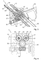
- Fig. 4 and Fig. 5 is a section of the spiral cable drive 7 in the field of drive device 23 and the drive converter means 48 closer, with a housing 47 of the spiral cable drive 7 for clarity in the 3 and 4 is shown transparent.
- 17 drives the drive means 23 to a worm gear 53, which is in engagement with a drive pinion 55.
- the drive pinion 55 in turn engages with spindle nuts 49, 51 of the drive transducer device 48, which receive the rotational drive movement of the drive pinion 55 and convert it into a translatory movement of the spiral cable 15 and 17, respectively.
- the drive pinion engages in an outer toothing 57 of the spindle nuts 49, 51 a.
- the drive mechanism is self-locking and self-locking need not, if desired, be implemented in another gear stage.
- spindle nut 49 is identical in construction to the spindle nut 51 and will be described in the following representative of this. Essentially identical in construction and only slightly simplified is the in the Fig. 6 and Fig. 7 shown spindle nut 49 is formed, which is therefore designated by the same reference numeral.
- the spindle nut 49 is arranged in a region of the spiral cable 15, in which the spiral cable 15 is not covered by the guide tube 25, so that the spindle nut 49 interacts directly with the spiral cable 15.
- the guide tube 25 is accordingly formed in two parts with a first part 63 facing the first end 19 of the spiral cable 15 and a second part 65 facing the second end 35 of the spiral cable 15.
- the spindle nut 49 surrounds or surrounds several, in this case six turns of the spiral cable 15 and is formed so complementary to the spiral cable 15 that the turns of the spiral cable 15 fit snugly in a spiral or spindle-shaped recess 54 of the spindle nut 49 place.
- rotation of the spiral nut 49 relative to the spiral cable 15 is caused by a slope of the turns of the spiral cable 15 translational movement of the spiral cable 15 relative to the spindle nut 49, which can already be transmitted by the low forces of the spindle nut 49 on the spiral cable 15.
- Fig. 8 is a section of the spiral cable 15 shown in isolation. It can be seen that the spiral cable 15 has a wire-like flexible shaft 67, on which a winding forming coil wire 69 is wound tightly without a reverse rotation of the flexible shaft 67 with embossing.
- a protective device formed with flocking 71 is provided, the flocculation with the flocking 71 surrounds the spiral cable 15 and the spiral cable 15th is glued on.
- the flocculation is designed such that the flock filaments 71 extend radially over the turns of the spiral wire 69, so that when the spiral cable 15 moves in the guide tube 25, only the flock filaments 71 are in contact with the guide tube 25.
- top elements of a soft-top hood or hard-top hood such as link flaps, closures, a parcel shelf or the like can be moved by a spiral cable drive, for which purpose a mechanism described above with two spiral cables can be provided, or alternatively a mechanism with a or more spiral cables.
Landscapes
- Engineering & Computer Science (AREA)
- Mechanical Engineering (AREA)
- Transmission Devices (AREA)
Applications Claiming Priority (1)
| Application Number | Priority Date | Filing Date | Title |
|---|---|---|---|
| DE102010015130A DE102010015130A1 (de) | 2010-04-16 | 2010-04-16 | Spiralkabelantrieb einer beweglichen Einrichtung eines Kraftfahrzeugs |
Publications (2)
| Publication Number | Publication Date |
|---|---|
| EP2377706A2 true EP2377706A2 (fr) | 2011-10-19 |
| EP2377706A3 EP2377706A3 (fr) | 2015-09-02 |
Family
ID=44065143
Family Applications (1)
| Application Number | Title | Priority Date | Filing Date |
|---|---|---|---|
| EP11162556.2A Withdrawn EP2377706A3 (fr) | 2010-04-16 | 2011-04-15 | Entraînement de câble spiralé d'un dispositif mobile d'un véhicule automobile |
Country Status (2)
| Country | Link |
|---|---|
| EP (1) | EP2377706A3 (fr) |
| DE (1) | DE102010015130A1 (fr) |
Families Citing this family (1)
| Publication number | Priority date | Publication date | Assignee | Title |
|---|---|---|---|---|
| DE102016104918A1 (de) | 2016-03-16 | 2017-09-21 | Küster Holding GmbH | Steigungskabel mit einem Mitnehmer und Verfahren zur Herstellung eines Steigungskabels mit einem Mitnehmer |
Citations (1)
| Publication number | Priority date | Publication date | Assignee | Title |
|---|---|---|---|---|
| DE20304478U1 (de) | 2003-03-20 | 2003-06-12 | Edscha Cabrio-Dachsysteme GmbH, 94491 Hengersberg | Vorrichtung zum Antrieb eines Steigungskabels |
Family Cites Families (6)
| Publication number | Priority date | Publication date | Assignee | Title |
|---|---|---|---|---|
| US2240087A (en) * | 1940-01-10 | 1941-04-29 | Barrett Engineering Company | Drive mechanism |
| IT1070631B (it) * | 1976-07-27 | 1985-04-02 | Roltra Spa | Accoppiamento di trasmissione a vite madre vite |
| DE3841460A1 (de) * | 1988-12-09 | 1990-06-13 | Willibald Neudert | Vorrichtung zur uebertragung von mechanischen kraeften in laengsrichtung mittels einer biegsamen stahldrahtspiralwelle |
| IT1242092B (it) * | 1990-10-09 | 1994-02-16 | Zani Srl | Dispositivo di azionamento per l'apertura e la chiusura di tettucci per autoveicoli |
| DE19800557A1 (de) * | 1998-01-09 | 1999-07-15 | Bosch Gmbh Robert | Betätigungsvorrichtung zum Verstellen eines Deckels, insbesondere Schiebedach eines Fahrzeugs |
| DE20312402U1 (de) * | 2003-08-07 | 2004-12-23 | Aumüller Aumatic GmbH | Betätigungseinrichtung |
-
2010
- 2010-04-16 DE DE102010015130A patent/DE102010015130A1/de not_active Ceased
-
2011
- 2011-04-15 EP EP11162556.2A patent/EP2377706A3/fr not_active Withdrawn
Patent Citations (1)
| Publication number | Priority date | Publication date | Assignee | Title |
|---|---|---|---|---|
| DE20304478U1 (de) | 2003-03-20 | 2003-06-12 | Edscha Cabrio-Dachsysteme GmbH, 94491 Hengersberg | Vorrichtung zum Antrieb eines Steigungskabels |
Also Published As
| Publication number | Publication date |
|---|---|
| DE102010015130A1 (de) | 2011-10-20 |
| EP2377706A3 (fr) | 2015-09-02 |
Similar Documents
| Publication | Publication Date | Title |
|---|---|---|
| EP1780361B1 (fr) | Dispositif d'actionnement pour l'entraînement motorisé d'un élément fonctionnel dans un véhicule automobile | |
| DE102017205721A1 (de) | Getriebeeinheit für ein Kraftfahrzeug | |
| DE102004036392A1 (de) | Rollosystem | |
| EP3266631A1 (fr) | Dispositif d'ombrage pour une vitre de véhicule automobile | |
| DE4314146C2 (de) | Vorrichtung zum Verstellen von bewegbaren Teilen an Fahrzeugen | |
| DE102016214774B4 (de) | Drehantriebseinrichtung mit lastabhängiger Bremse | |
| EP1097657B1 (fr) | Unité téléscopique d'entraínement | |
| DE102013200359A1 (de) | Getriebe-Antriebseinheit sowie Verwendung einer Getriebe-Antriebseinheit | |
| EP1134453B1 (fr) | Actionneur pour partie réglable d'un véhicule | |
| EP2325429B1 (fr) | Entraînement de capote | |
| EP2377706A2 (fr) | Entraînement de câble spiralé d'un dispositif mobile d'un véhicule automobile | |
| DE102008042159A1 (de) | Schneckengetriebe sowie Verstellantrieb | |
| DE102007027219A1 (de) | Linearantrieb für eine Heckklappe oder dergleichen | |
| DE19617226C2 (de) | Abschaltvorrichtung für den Antrieb eines zwischen Endstellungen verstellbaren Teils eines Fahrzeuges | |
| DE102011113429B4 (de) | Antriebsvorrichtung für ein bewegliches Dachelement eines Fahrzeugdachs und Fahrzeugdach | |
| DE202017102027U1 (de) | Getriebeeinheit für ein Kraftfahrzeug | |
| DE102018104024B4 (de) | Stellelement für ein Luftleitelement eines Kraftfahrzeugs | |
| EP0571733B1 (fr) | Système de retenue pour ceinture de sécurité | |
| EP1394924A1 (fr) | Dispositif autobloquant pour l'entraínement de systèmes d'essuie-glace | |
| DE102012105075A1 (de) | Verstellvorrichtung | |
| DE202012102150U1 (de) | Verstellvorrichtung | |
| DE102008052843A1 (de) | Antriebseinheit für Verstelleinrichtungen in Kraftfahrzeugen | |
| DE19549791B4 (de) | Stellantrieb | |
| DE102017205724A1 (de) | Getriebeeinheit für ein Kraftfahrzeug | |
| DE2058567A1 (de) | Mechanismus fuer einen elektrischen Scheibenheber |
Legal Events
| Date | Code | Title | Description |
|---|---|---|---|
| AK | Designated contracting states |
Kind code of ref document: A2 Designated state(s): AL AT BE BG CH CY CZ DE DK EE ES FI FR GB GR HR HU IE IS IT LI LT LU LV MC MK MT NL NO PL PT RO RS SE SI SK SM TR |
|
| AX | Request for extension of the european patent |
Extension state: BA ME |
|
| PUAI | Public reference made under article 153(3) epc to a published international application that has entered the european phase |
Free format text: ORIGINAL CODE: 0009012 |
|
| RAP1 | Party data changed (applicant data changed or rights of an application transferred) |
Owner name: VALMET AUTOMOTIVE OY |
|
| PUAL | Search report despatched |
Free format text: ORIGINAL CODE: 0009013 |
|
| AK | Designated contracting states |
Kind code of ref document: A3 Designated state(s): AL AT BE BG CH CY CZ DE DK EE ES FI FR GB GR HR HU IE IS IT LI LT LU LV MC MK MT NL NO PL PT RO RS SE SI SK SM TR |
|
| AX | Request for extension of the european patent |
Extension state: BA ME |
|
| RIC1 | Information provided on ipc code assigned before grant |
Ipc: B60J 7/057 20060101AFI20150727BHEP |
|
| STAA | Information on the status of an ep patent application or granted ep patent |
Free format text: STATUS: THE APPLICATION IS DEEMED TO BE WITHDRAWN |
|
| 18D | Application deemed to be withdrawn |
Effective date: 20160303 |