EP2377781A2 - Rayonnage d'emmagasinage avec transstockeur - Google Patents
Rayonnage d'emmagasinage avec transstockeur Download PDFInfo
- Publication number
- EP2377781A2 EP2377781A2 EP11003150A EP11003150A EP2377781A2 EP 2377781 A2 EP2377781 A2 EP 2377781A2 EP 11003150 A EP11003150 A EP 11003150A EP 11003150 A EP11003150 A EP 11003150A EP 2377781 A2 EP2377781 A2 EP 2377781A2
- Authority
- EP
- European Patent Office
- Prior art keywords
- rack
- conveyor
- storage
- bridge
- rack aisle
- Prior art date
- Legal status (The legal status is an assumption and is not a legal conclusion. Google has not performed a legal analysis and makes no representation as to the accuracy of the status listed.)
- Withdrawn
Links
- 238000000034 method Methods 0.000 claims abstract description 10
- 238000012546 transfer Methods 0.000 claims description 50
- 230000001105 regulatory effect Effects 0.000 description 3
- 230000015572 biosynthetic process Effects 0.000 description 2
- 230000000694 effects Effects 0.000 description 2
- 230000032258 transport Effects 0.000 description 2
- 238000013461 design Methods 0.000 description 1
- 238000011161 development Methods 0.000 description 1
- 230000003287 optical effect Effects 0.000 description 1
- 238000012549 training Methods 0.000 description 1
Images



Classifications
-
- B—PERFORMING OPERATIONS; TRANSPORTING
- B65—CONVEYING; PACKING; STORING; HANDLING THIN OR FILAMENTARY MATERIAL
- B65G—TRANSPORT OR STORAGE DEVICES, e.g. CONVEYORS FOR LOADING OR TIPPING, SHOP CONVEYOR SYSTEMS OR PNEUMATIC TUBE CONVEYORS
- B65G1/00—Storing articles, individually or in orderly arrangement, in warehouses or magazines
- B65G1/02—Storage devices
- B65G1/04—Storage devices mechanical
- B65G1/0485—Check-in, check-out devices
Definitions
- the invention relates to a rack storage with at least two rack aisles lying between shelves and movable therein stacker cranes, wherein a transfer point is provided for each rack aisle, from which or to record the storage and retrieval equipment stored goods. Furthermore, the invention relates to a storage and retrieval unit for such a shelf storage and a method for loading and unloading of stored goods in a rack storage.
- Modern shelf warehouses provide storage space for thousands of palletized goods in storage, with rack aisles or corridors being left free between the individual storage bins, in which storage and retrieval machines ensure that goods are loaded and unloaded at most fully automatically.
- a separate transfer point is provided for each storage and retrieval unit in each rack aisle, on which or from which stored goods on a respectively the rack aisle associated conveyor belt can be loaded or unloaded.
- the EP 0 442 000 A1 shows a shelf warehouse with several rack aisles with it moved storage and retrieval devices and transfer points. Along the front of the shelf storage runs a long conveyor that transports stored goods to the transfer points. The conveyor systems must be relatively space-intensive around the shelves be guided around, which is also costly and means a longer delivery time for the stored goods.
- the storage product extends directly or via an intermediate conveyor belt to the second storage and retrieval unit.
- the first storage and retrieval unit can not fulfill its actual task - to serve the first rack aisle.
- the object of the invention is therefore to provide a comparison with the prior art improved shelf storage.
- the cumbersome, costly and often relatively long conveyor systems are to be avoided to the more distant aisles.
- the first storage and retrieval unit should be able to be used as efficiently and as multifunctionally as possible.
- the time in which the first storage and retrieval unit is at the transfer point of the first rack aisle to be used to forward stored goods to a second storage and retrieval unit can.
- This object is achieved in that directly adjacent to the transfer point of the first rack avenue is provided across the first rack aisle conveyor bridge is brought over the stored goods from or to the transfer point of the second rack aisle, the conveyor bridge crosses the travel of the stacker crane and between the Shelves is whippable. This can In the area of the transfer point of the first rack aisle stored goods for the second rack aisle are relatively quickly forwarded to or from the main conveyor system. By crossing the first rack aisle by means of the bridge, a complicated diverting of the conveyor system in the rack storage is avoided.
- whippable bridge on the aisle alley it is thus possible on the one hand to substantially reduce the need for funding and to make the promotion of goods less cumbersome and yet the entire travel for the storage and retrieval device along the rack aisle between the shelves unrestricted - on both sides the conveyor bridge - to be able to use.
- a preferred embodiment of the present invention may provide that the conveyor bridge is removable from an open, bridging position. It should be ensured that the conveyor bridge is only opened when the first storage and retrieval unit is at the transfer point of the first rack aisle or at a storage location.
- a further preferred embodiment may provide that between the first and second rack aisle an intermediate conveyor system is arranged substantially transversely to the rack aisles, one end of the intermediate conveyor the transfer point of the second rack aisle and the other end forms a bridge transfer point to be whipped across the first rack aisle conveyor bridge.
- the conveyor bridge between the open position and a retracted position is movable, the conveyor bridge from the retracted position in the open position is extendable across the first rack aisle.
- An example of this is for an extendable conveyor bridge on the WO 2006/068443 A1 directed.
- the provided in the first rack aisle storage and retrieval unit moves freely only in the retracted position of the conveyor bridge in the first rack alley.
- a controller or control monitor the corresponding operations.
- the bridge itself can protrude, for example, from both sides of the rack aisle extendable and retractable.
- the conveyor bridge with the provided in the first rack aisle first storage and retrieval unit moves.
- the conveyor bridge is arranged on the first storage and retrieval unit or connected directly to this.
- the first storage and retrieval unit while it performs its activity of loading and unloading of stored goods from the first transfer point, serve as a link for the conveyor system of the second rack aisle via the entrained bridge.
- the transfer points preferably arranged one above the other, each have a delivery point for storage goods to be dispensed and an acceptance point for goods to be accepted. Due to this two-storey arrangement, the individual, mostly palletized storage goods can be guided on one level towards the exit and on the other level at the same time the parking space can be moved.
- the stacker cranes can each have a conveyor for storing and retrieving the stored goods.
- the storage and retrieval unit comprises a chassis and a (first) associated with the chassis conveyor for storage and retrieval of stored goods.
- a second, preferably aligned parallel to the first, conveyor is provided which forms a connected to the chassis conveyor bridge for the transport of stored goods across the rack aisle.
- this stacker crane on the one hand serves to operate the first rack aisle and on the other hand as a connecting part of the conveyor system for the second rack aisle.
- the second conveyor device forms two preferably arranged one above the other, conveying in opposite directions conveyor bridges.
- the storage and retrieval unit carries or has further bridges as a connecting piece for a third and fourth conveyor system.
- Protection is also desired for a method for loading and unloading of stored goods in a rack storage, while stored or delivered from the transfer point of the first rack aisle during the provided in the first rack aisle first storage and retrieval device at the same time on the directly next to the transfer point the first rack aisle open delivery bridge stored goods is transported from or to the transfer point of the second rack aisle.
- Fig. 1 shows a shelf storage 10 according to the prior art, wherein in the first rack aisle 1, the first storage and retrieval unit 3 can be moved on a rail, not shown.
- This storage and retrieval unit 3 can position stored goods 5 in the high bay via a known conveying device 8 or pick it up and deliver it to a transfer point Ü1 of the first rack aisle 1. From this transfer point Ü1, the stored material 5 arrives at the first rack aisle 1 associated conveyor 12a via the intersection 13 during unloading Main conveyor system 12 and from there to the delivery and delivery point 15. From the intersection 13 branches off another conveyor 12b, which leads relatively long and cumbersome along the shelf storage wall 16 to the transfer point Ü2 for the aisle 2.
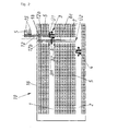
- Fig. 2 the solution according to the invention for an improved shelf storage 10 is shown.
- the first storage and retrieval unit 3 has not only the conveyor 8 for storing and retrieving stored goods 5 in the first rack aisle 1, but also a bridge 6 as a conveyor system connecting piece so to speak. This can - while the storage and retrieval unit 3 is at the transfer point Ü1 - directly next to the bridge 6 stored goods 5 from the connected to the transfer point Ü2 for the aisle 2 intermediate conveyor 7 transverse to the aisle 1. From this Fig.
- the first conveying path leads from the delivery and delivery point 15 to the transfer point Ü1 and is formed by the conveyor 12, the intersection 13 and the conveyor 12a.
- the second conveying path leads from the delivery and delivery point 15 Transfer point Ü2 for the second rack aisle 2 and is formed by the conveyor 12, the intersection 13, the conveyor 12b, the conveyor bridge 6 and the intermediate conveyor 7.
- Each rack aisle 1 or 2 essentially forms the path of travel for a stacker crane 3 over its entire length. This travel path is crossed by the conveyor bridge 6 or by the second conveyor path. As a result, the travel path is subdivided into a first travel path lying in front of the bridge 6 and a second travel path lying after the bridge 6.
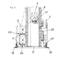
- Fig. 3 shows a side view of the first rack aisle 1 movable and multifunctional usable first storage and retrieval unit 3.
- the chassis 11 of the stacker crane 3 is shown, which can be moved by drive motors 19 along the bottom of the rack aisle 1 of the rack 10 mounted rail 18 .
- This storage and retrieval unit 3 has as a main component on the conveyor 8, which can be moved, for example via a lifting 17 in height and the stored goods 5 transversely to the aisle 1 and unloads.
- the entire storage and retrieval unit 3 can be controlled or regulated by a control unit 20.
- a double-decker second conveyor 9 is provided on the chassis 11 of the stacker crane 3, which on the one hand forms a bridge 6a, which corresponds with a corresponding delivery point "out” towards the bridge transfer point BH with the conveyor 12b, while the conveyor bridge 6b with the receiving station "in” corresponds.
- the conveyor 8 may be double-decker.
- Fig. 4 and 5 show in detail in plan view the storage and retrieval unit 3, wherein in Fig. 4 this storage and retrieval unit 3 is positioned at the transfer point Ü1, while directly next to the moving bridge 6 stored goods 5 between conveyor 12b and intermediate conveyor 7 back and transported.
- the bridge 6 is arranged at a not directly adjacent to the transfer point Ü1 position of the rack aisle 1.
- the bridge 6 is designed as a ride-on bridge - of great advantage if these positions are as close to each other, otherwise the stacker crane 3 unnecessarily long should be trained.
- "Directly next to" according to claim 1 means that at most about three storage spaces between transfer point Ü1 and conveyor bridge 6 are.
- Fig. 6 again shows in section AA the extendable bridges 6c in retracted position E, wherein the conveyor 8 of the stacker crane 3 is in the raised position and the bridge 6a and 6b or its conveyor 9 serve in bridge-forming position B of the conveyor system connection.
- a rack storage is thus shown in which in the transfer position Ü1 the rack aisle 1 a bridge 6 is beaten to the aisle 2 - either by a taken with the stacker crane 3 bridge 6a and 6b with conveyor 9 or by a separate extendable Bridge 6c including conveyor 9, which can bridge, for example, from both sides of the aisle 1 each half the rack aisle 1.
- This has the advantage that it is structurally easier compared to the outside guiding the conveyor system 12.
- two operations can be performed simultaneously (preferably from the storage and retrieval unit 3), namely from the aisle 1 to unload and load stored goods 5 and over the bridge 6 and its conveyor 9 stored goods to promote to or from the aisle alley 2.
- an extendable bridge 6c can be provided that the extension and retraction of the bridge 6c monitored by a control or regulating unit. This allows the extended state only when the storage and retrieval unit 3 does not cross the second conveying path formed by the bridge 6c. That is, as soon as the control or regulating unit receives signals that the storage and retrieval unit 3 will cross the second conveying path, a retraction signal is transmitted to the extendable bridge 6c, so that these move from the extended positions to the retracted position. Collisions between the storage and retrieval unit 3 and the extendable bridge 6c are thereby avoided.
- a stacker crane 3 could not travel in both travel paths at all. It could only be provided that the bridge 6c is arranged above the control panel so that the stacker crane 3 passes underneath. Then the bridge 6c would not have to be retracted. Seen from above, the conveyor bridge 6c also crosses the travel path of the stacker crane 3.
Landscapes
- Engineering & Computer Science (AREA)
- Mechanical Engineering (AREA)
- Warehouses Or Storage Devices (AREA)
Applications Claiming Priority (1)
| Application Number | Priority Date | Filing Date | Title |
|---|---|---|---|
| AT6182010A AT509754A1 (de) | 2010-04-16 | 2010-04-16 | Regallager mit regalbediengerät |
Publications (2)
| Publication Number | Publication Date |
|---|---|
| EP2377781A2 true EP2377781A2 (fr) | 2011-10-19 |
| EP2377781A3 EP2377781A3 (fr) | 2014-07-09 |
Family
ID=44121446
Family Applications (1)
| Application Number | Title | Priority Date | Filing Date |
|---|---|---|---|
| EP11003150.7A Withdrawn EP2377781A3 (fr) | 2010-04-16 | 2011-04-14 | Rayonnage d'emmagasinage avec transstockeur |
Country Status (2)
| Country | Link |
|---|---|
| EP (1) | EP2377781A3 (fr) |
| AT (2) | AT509754A1 (fr) |
Cited By (1)
| Publication number | Priority date | Publication date | Assignee | Title |
|---|---|---|---|---|
| CN111301922A (zh) * | 2020-03-31 | 2020-06-19 | 深圳市美瑞安科技有限公司 | 一种夹抱式存取pcb成品的智能立体仓库及仓储方法 |
Citations (5)
| Publication number | Priority date | Publication date | Assignee | Title |
|---|---|---|---|---|
| EP0407703A1 (fr) | 1989-07-12 | 1991-01-16 | KEURO Besitz GmbH & Co. EDV-Dienstleistungs KG | Procédé et dispositif pour stocker et déstocker des caissons contenant des matériaux en forme de bâton ou de plaque dans un magasin à rayonnage |
| EP0442000A1 (fr) | 1990-02-13 | 1991-08-21 | GEBHARDT FÖRDERTECHNIK GmbH Austria | Cabine de préparation des commandes |
| EP0961743B1 (fr) | 1996-07-04 | 2003-04-16 | Alcatel | Systeme de transport avec vehicules de transport guides par rails |
| WO2006068443A1 (fr) | 2004-12-22 | 2006-06-29 | Loteco, Inc. | Transporteur telescopique |
| EP2052994A1 (fr) | 2007-10-24 | 2009-04-29 | Savoye | Transstockeur avec nacelle à convoyeur embarqué pour magasin de stockage automatisé |
Family Cites Families (11)
| Publication number | Priority date | Publication date | Assignee | Title |
|---|---|---|---|---|
| DE2843201A1 (de) * | 1978-10-04 | 1980-04-17 | Enzinger Union Werke Ag | Hochregallager, insbesondere fuer brauereien o.dgl. betriebe |
| JPS56135354A (en) * | 1980-03-24 | 1981-10-22 | Toyo Umpanki Co Ltd | Shifting device for pallet or the like |
| CH650218A5 (de) * | 1981-05-05 | 1985-07-15 | Inventio Ag | Uebergabeeinrichtung fuer paletten und stueckgueter. |
| JPS6132883Y2 (fr) * | 1981-06-16 | 1986-09-25 | ||
| NL9100632A (nl) * | 1991-04-10 | 1992-11-02 | Ind Contractors Holland Bv | Laad/los-inrichting, voertuig voorzien van een dergelijke inrichting, laad/los-station en werkwijze gebruikmakend van dat voertuig. |
| WO1996019400A1 (fr) * | 1994-12-21 | 1996-06-27 | Progressive Solutions, Inc. | Procede et systeme de manipulation de produits |
| US6116842A (en) * | 1998-10-02 | 2000-09-12 | Harris; Richard D. | Transfer car for a conveyor system |
| AT407148B (de) * | 1999-02-15 | 2000-12-27 | Lager Technik Gmbh | Transporteinrichtung, insbesondere innerbetriebliche transporteinrichtung mit mehreren förderbahnen |
| US6321138B1 (en) * | 2000-09-15 | 2001-11-20 | Woodson Incorporated | Storage and retrieval system with automated order make up |
| DE102007060730B4 (de) * | 2006-12-18 | 2009-05-14 | Albert Schuhmann | Einfahrregalsystem |
| DE102007051238A1 (de) * | 2007-10-26 | 2009-04-30 | Dematic Gmbh | Verfahren und System zum Ein- und Auslagern von Behältern in ein oder aus einem Lager |
-
2010
- 2010-04-16 AT AT6182010A patent/AT509754A1/de active IP Right Grant
- 2010-04-16 AT ATGM8024/2012U patent/AT12756U1/de not_active IP Right Cessation
-
2011
- 2011-04-14 EP EP11003150.7A patent/EP2377781A3/fr not_active Withdrawn
Patent Citations (5)
| Publication number | Priority date | Publication date | Assignee | Title |
|---|---|---|---|---|
| EP0407703A1 (fr) | 1989-07-12 | 1991-01-16 | KEURO Besitz GmbH & Co. EDV-Dienstleistungs KG | Procédé et dispositif pour stocker et déstocker des caissons contenant des matériaux en forme de bâton ou de plaque dans un magasin à rayonnage |
| EP0442000A1 (fr) | 1990-02-13 | 1991-08-21 | GEBHARDT FÖRDERTECHNIK GmbH Austria | Cabine de préparation des commandes |
| EP0961743B1 (fr) | 1996-07-04 | 2003-04-16 | Alcatel | Systeme de transport avec vehicules de transport guides par rails |
| WO2006068443A1 (fr) | 2004-12-22 | 2006-06-29 | Loteco, Inc. | Transporteur telescopique |
| EP2052994A1 (fr) | 2007-10-24 | 2009-04-29 | Savoye | Transstockeur avec nacelle à convoyeur embarqué pour magasin de stockage automatisé |
Cited By (1)
| Publication number | Priority date | Publication date | Assignee | Title |
|---|---|---|---|---|
| CN111301922A (zh) * | 2020-03-31 | 2020-06-19 | 深圳市美瑞安科技有限公司 | 一种夹抱式存取pcb成品的智能立体仓库及仓储方法 |
Also Published As
| Publication number | Publication date |
|---|---|
| AT12756U1 (de) | 2012-11-15 |
| EP2377781A3 (fr) | 2014-07-09 |
| AT509754A1 (de) | 2011-11-15 |
Similar Documents
| Publication | Publication Date | Title |
|---|---|---|
| EP2794430B1 (fr) | Système d'emmagasinage à rayonnages et son procédé de fonctionnement | |
| DE102011106677B4 (de) | System und Verfahren zum Ein- und Auslagern eines Lagerguts in ein und aus einem Regal | |
| AT509294B1 (de) | Regallagersystem | |
| DE102011014394C5 (de) | Zirkulares Roaming für ein Lager- und Kommissioniersystem | |
| EP2287093B1 (fr) | Système de rayonnage et procédé de fonctionnement d'un système de rayonnage | |
| EP2128047B1 (fr) | Dispositif de réception pour un véhicule transporteur et procédé pour son utilisation | |
| DE202016009161U1 (de) | Lagersystem | |
| AT511490A1 (de) | Regallagersystem | |
| DE10234150A1 (de) | Verfahren und System zum Bedienen eines Regals vorzugsweise in einer Kommissionieranlage | |
| EP2753558B1 (fr) | Poste de préparation de commande et méthode de préparation de commande d'articles avec aide au chargement | |
| EP2354045A1 (fr) | Rayonnage | |
| EP0608689A1 (fr) | Dispositif de transport avec ou moins un engin pour l'extraction et le rangement d'une charge dans des cellules de rayonnage | |
| EP1882648B1 (fr) | Procédé destiné à stocker et déstocker des marchandises au détail, en particulier de caisses de boissons, et système de stockage correspondant | |
| DE102021105391A1 (de) | Regalbediensystem | |
| EP3057887B1 (fr) | Système de stockage pourvu de structures de stockage amenées en rotation dans différents plans | |
| EP1676808A2 (fr) | Transstockeur et rayonnage d'emmagasinage surélevé avec un tel transstockeur | |
| DE202004007004U1 (de) | Regallager mit Mehrebenen-Lagervorzone | |
| EP0442000B1 (fr) | Cabine de préparation des commandes | |
| AT12756U1 (de) | Regallager mit Regalbediengerät | |
| EP3473562A1 (fr) | Procédé et technologie de stockage des étagères hautes permettant de stocker la marchandise au moyen du stockage transversal orthogonal | |
| DE202005013680U1 (de) | Regalfahrzeug für Behälterlager | |
| EP3974350A1 (fr) | Procédé de fonctionnement d'un système d'entreposage sur étag?res et système d'entreposage sur étag?res | |
| DE29719413U1 (de) | Regalbediengerät | |
| DE10059995A1 (de) | Koppelglied zwischen einem Regallager und mindestens einem Vertikalförderer | |
| DE2711349A1 (de) | Flurfahrendes lagerhausfahrzeug |
Legal Events
| Date | Code | Title | Description |
|---|---|---|---|
| AK | Designated contracting states |
Kind code of ref document: A2 Designated state(s): AL AT BE BG CH CY CZ DE DK EE ES FI FR GB GR HR HU IE IS IT LI LT LU LV MC MK MT NL NO PL PT RO RS SE SI SK SM TR |
|
| AX | Request for extension of the european patent |
Extension state: BA ME |
|
| PUAI | Public reference made under article 153(3) epc to a published international application that has entered the european phase |
Free format text: ORIGINAL CODE: 0009012 |
|
| RIC1 | Information provided on ipc code assigned before grant |
Ipc: B65G 1/04 20060101AFI20140211BHEP |
|
| PUAL | Search report despatched |
Free format text: ORIGINAL CODE: 0009013 |
|
| AK | Designated contracting states |
Kind code of ref document: A3 Designated state(s): AL AT BE BG CH CY CZ DE DK EE ES FI FR GB GR HR HU IE IS IT LI LT LU LV MC MK MT NL NO PL PT RO RS SE SI SK SM TR |
|
| AX | Request for extension of the european patent |
Extension state: BA ME |
|
| RIC1 | Information provided on ipc code assigned before grant |
Ipc: B65G 1/04 20060101AFI20140605BHEP |
|
| STAA | Information on the status of an ep patent application or granted ep patent |
Free format text: STATUS: THE APPLICATION IS DEEMED TO BE WITHDRAWN |
|
| 18D | Application deemed to be withdrawn |
Effective date: 20141101 |