EP2378035B1 - Procédé d' alignement d'un tube vertical téléscopique doté d'une plaque de tête ou d'assise - Google Patents
Procédé d' alignement d'un tube vertical téléscopique doté d'une plaque de tête ou d'assise Download PDFInfo
- Publication number
- EP2378035B1 EP2378035B1 EP11154457.3A EP11154457A EP2378035B1 EP 2378035 B1 EP2378035 B1 EP 2378035B1 EP 11154457 A EP11154457 A EP 11154457A EP 2378035 B1 EP2378035 B1 EP 2378035B1
- Authority
- EP
- European Patent Office
- Prior art keywords
- base plate
- head
- plate
- counter
- tube
- Prior art date
- Legal status (The legal status is an assumption and is not a legal conclusion. Google has not performed a legal analysis and makes no representation as to the accuracy of the status listed.)
- Active
Links
Images

Classifications
-
- E—FIXED CONSTRUCTIONS
- E04—BUILDING
- E04G—SCAFFOLDING; FORMS; SHUTTERING; BUILDING IMPLEMENTS OR AIDS, OR THEIR USE; HANDLING BUILDING MATERIALS ON THE SITE; REPAIRING, BREAKING-UP OR OTHER WORK ON EXISTING BUILDINGS
- E04G25/00—Shores or struts; Chocks
- E04G25/04—Shores or struts; Chocks telescopic
- E04G25/06—Shores or struts; Chocks telescopic with parts held together by positive means
-
- E—FIXED CONSTRUCTIONS
- E04—BUILDING
- E04G—SCAFFOLDING; FORMS; SHUTTERING; BUILDING IMPLEMENTS OR AIDS, OR THEIR USE; HANDLING BUILDING MATERIALS ON THE SITE; REPAIRING, BREAKING-UP OR OTHER WORK ON EXISTING BUILDINGS
- E04G25/00—Shores or struts; Chocks
-
- E—FIXED CONSTRUCTIONS
- E04—BUILDING
- E04G—SCAFFOLDING; FORMS; SHUTTERING; BUILDING IMPLEMENTS OR AIDS, OR THEIR USE; HANDLING BUILDING MATERIALS ON THE SITE; REPAIRING, BREAKING-UP OR OTHER WORK ON EXISTING BUILDINGS
- E04G25/00—Shores or struts; Chocks
- E04G25/04—Shores or struts; Chocks telescopic
- E04G25/06—Shores or struts; Chocks telescopic with parts held together by positive means
- E04G25/061—Shores or struts; Chocks telescopic with parts held together by positive means by pins
-
- E—FIXED CONSTRUCTIONS
- E04—BUILDING
- E04G—SCAFFOLDING; FORMS; SHUTTERING; BUILDING IMPLEMENTS OR AIDS, OR THEIR USE; HANDLING BUILDING MATERIALS ON THE SITE; REPAIRING, BREAKING-UP OR OTHER WORK ON EXISTING BUILDINGS
- E04G25/00—Shores or struts; Chocks
- E04G25/04—Shores or struts; Chocks telescopic
- E04G25/06—Shores or struts; Chocks telescopic with parts held together by positive means
- E04G25/065—Shores or struts; Chocks telescopic with parts held together by positive means by a threaded nut
-
- E—FIXED CONSTRUCTIONS
- E04—BUILDING
- E04G—SCAFFOLDING; FORMS; SHUTTERING; BUILDING IMPLEMENTS OR AIDS, OR THEIR USE; HANDLING BUILDING MATERIALS ON THE SITE; REPAIRING, BREAKING-UP OR OTHER WORK ON EXISTING BUILDINGS
- E04G25/00—Shores or struts; Chocks
- E04G2025/006—Heads therefor, e.g. pivotable
Definitions
- the invention relates to a method for aligning, by means of a lever tool, of a telescopic vertical tube, which has an outer tube and an inner tube which can be displaced in the outer tube, with a frontal head and / or foot plate.
- Such telescopic vertical tubes are used for setting up ceiling formwork, shoring or scaffolding.
- Vertical pipes are also referred to as a prop and z.
- As for formwork as scaffolding tube as part of a so-called modular scaffolding (spatial structure) or as part of a vertical frame used in facade scaffolding. Regardless of the purpose, these must be adjustable in height.
- the telescopic vertical tubes on an outer tube and an inner tube which is displaceable and fixable for length and height adjustment in the outer tube and thus telescopic. This height adjustment can be done by moving the inner tube in stages or continuously, for example by inserted in through holes pin or thread.
- Such vertical tubes have to increase the footprint on the front side of a head or foot plate at one or both free ends. This serves to increase the footprint, so that a lower contact pressure against the counter surface, for example, a floor, a ceiling or a wall results. Without a foot plate, the vertical tube would possibly press into the ground or it could result in setting movements under load.
- the top or bottom plates with recesses on the edge, so that a lever tool in between Plate and counter surface can be introduced.
- a lever tool in between Plate and counter surface can be introduced.
- the peripheral recesses offer in contrast to the impact protector according to the prior art, the possibility to be introduced without additional material and with low production costs, for example by means of proven manufacturing steps for manufacturing and attaching the head or foot plate.
- the displacement of the pipes can be very metered and without the hammering associated material stress and noise development done.
- "Edge recesses” do not mean that they may only be on the edge. Of course, the recesses can also extend inwards. It is crucial that at least the edge offers suitable points of attack for a lever tool.
- a spindle is used as an inner tube, it may optionally be inserted into the outer tube sufficiently loosely, so that the vertical tube can absorb only compressive forces in the axial direction.
- the compressive forces are absorbed by a screwed onto the spindle nut or more generally a mating thread, which in turn is supported against the opening of the outer tube or generally against the outer tube.
- the spindle and nut should be designed so that even with the maximum unscrewing of the spindle, this is performed sufficiently in the outer tube.
- the mother preferably has wings for turning without tools.
- the spindle can be inserted at the upper or lower end of the vertical tube and thus form a head or foot spindle.
- Such spindles preferably comprise a head or foot plate, a threaded tube and a spindle nut. These threaded spindles are z. B. also plugged into modular scaffolding vertical handles or vertical tubes of a facade or supporting framework.
- the recesses in the plates are designed such that by means of leverage the static friction between the footprint and counter surface can be overcome on the site and can use a lower resistance forming sliding friction.
- the person skilled in the art will therefore choose the height and depth of the recess in such a way that conventional construction tools, such as a bar iron / Qfoot, can be used such that a sufficiently high lateral pushing force can be generated by engaging the lever tool in the mating surface when the lever movement is initiated. If the recess is too shallow, the lever tool can not be used or generate sufficient lateral force. If the recess is too high, the lever factor is reduced.
- the lever tool may be inserted too deep and essentially only a vertical force and not the desired sideways force is generated. If the recess is not sufficiently deep, the vertical force is hardly generated when levering and there is - if any - only a very short sideways movement. Furthermore, the operator has to adjust and operate the lever tool again and again.
- the recesses are such that, by actuating the lever tool inserted therein, the head or foot plate is lifted off the opposing surface. This reduces the contact or sliding friction between footprint and mating surface and the alignment requires less force.
- the two above-mentioned force actions of the lever namely friction-reducing lifting of the head or foot plate from the counter surface and applying a lateral displacement force, simultaneously by a single pivotal movement of the lever.
- a force vector is formed away from the counter surface and in the direction of the vertical tube longitudinal axis.
- the dimensions named for the vertical tube, the head or foot plate and the recess have proven to be particularly suitable for construction sites and are user-friendly.
- the vertical tube is part of a scaffolding, z. B. as scaffolding tube or as the two vertical posts in a scaffolding frame.
- a scaffolding frame two parallel vertical tubes are connected to each other at the bottom and top of the outer tube by horizontal beams to form a frame.
- So-called module stands are preferably connected by means of prefabricated system components and have corresponding connection options. This may, for example, be a system with vertical stem stakes and wedge heads on the bars and diagonals for hanging in the plates. Alternatively, this may be a system with prefabricated frames that are connected and unlaced by means of bars and diagonals.
- the vertical tube is preferably used for formwork or support purposes, for. B. as a prop. Also, the tube or the support is reversible used, so that the terms “top” “bottom”, “top plate” and “base plate” are meaningfully interchangeable and not limiting.
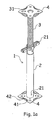
- FIG. 1b shows another embodiment of the prop 1 , which only in the mounting principle 21 of Fig. 1a different.
- This height adjustment can be done by moving the inner tube in stages by inserted into aligned through holes through inner and outer tube pins. This is done coarse adjustment.
- to Fine adjustment is a stepless adjustment by means of thread, as in FIG. 1a , provided, however, only in sections, ie to bridge the area between two through holes.
- the thread is cost and production cost saving only on a short section of the outer tube 2 is provided
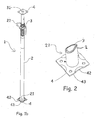
- FIG. 2 shows by way of example a foot plate 4 in detail which can be used in the method according to the invention, wherein all explanations are of course transferable to a corresponding top plate.
- the base plate 4 is attached, which is usually done by inserting a pipe end 21 in a circular recess of the contemplatplattenrohlings 4 or by placing a pipe end 21 on the Schwarzplattenrohling 4 to this circular recess followed by point or sections welding ,
- the foot plate 4 corresponds to the material and dimensions commonly used foot plates.
- the recesses 42 are introduced. These extend only in the central region of the edge 43 , so that in the region of the recesses 42 higher forces can be introduced without causing deformations of the base plate 4 .
- the recess 42 is formed by deformation of the base plate, for example by punching. Preferably, this is a bow-like segment.
- the deformed region of the edge 43 preferably makes up only 30 to 60%, preferably 35 to 45%, of the edge length.
- the deformed portion, which forms the recess 42 is arcuate in plan view, wherein the arc lines on the outer edge 43 of the base plate 4 at an obtuse angle less than 65 °, preferably less than 45 ° meet.
- This embodiment serves for improved fatigue strength and prevents tearing in the region of the edge 43 of the recess 42 .
- the foot plate can also be round with circumferential recess. It could then be applied at any point of the lever and thus carried out a shift directly in any direction, theoretically only three recesses distributed in 120 ° intervals would suffice. Also more recesses are conceivable analogously. However, 4 recesses distributed at 90 ° intervals are preferred, as they correspond to the usual thinking at right angles and ensure higher strength of the edge against bending up. This applies regardless of the geometry of the foot plate.
- FIG. 3 Finally, is a technical drawing of the base plate with exemplary dimensions in mm.
Landscapes
- Engineering & Computer Science (AREA)
- Architecture (AREA)
- Mechanical Engineering (AREA)
- Civil Engineering (AREA)
- Structural Engineering (AREA)
- Forms Removed On Construction Sites Or Auxiliary Members Thereof (AREA)
- Casings For Electric Apparatus (AREA)
- Mutual Connection Of Rods And Tubes (AREA)
Claims (4)
- Procédé d'alignement au moyen d'un outil à levier d'un tube vertical télescopique (1) étant sous charge ayant une plaque de tête et/ou de base frontale (4) sur au moins l'un de ses bouts (21, 31), dans lequel la plaque de tête et/ou de base (4) s'appuie contre une contre-surface avec sa zone de contact (41 et dans lequel la plaque de tête et/ou de base (4) s'appuie contre une contre-surface avec sa surface d'appui et dans lequel la plaque de tête et/ou de base (4) sur le côté de bord a des renfoncements (42) de telle façon qu'un outil à levier est amenable être la plaque de tête et/ou de base (4) et la contre-surface, ayant les étapes suivantes :a. insertion d'un bout de l'outil à levier dans le renfoncement (42) entre la plaque de tête et/ou de base (4) et la contre-surface ; etb. mouvement de l'outil à levier et de ce fait déplacement du tube vertical le long de la contre-surface.
- Procédé d'alignement selon la revendication précédente, dans lequel pendant la mise en oeuvre de l'étape b)c. l'outil à levier, lors du basculement de la partie de manipulation de l'outil à levier par l'utilisateur vers le tube vertical, simultanément soulève la plaque de tête et/ou de base (4) de la contre-surface et déplace la plaque de tête et/ou de base (4) en direction vers le mouvement de basculement le long de la contre-surface.
- Procédé d'alignement selon l'une des revendications précédentes, dans lequel les renfoncements (42) sont de telle façon, que la plaque de tête et/ou de base (4) est retirée de 5 - 20 mm, préférablement de 6 - 20 mm du plan de la surface d'appui dans la région du renfoncement.
- Procédé d'alignement selon l'une des revendications précédentes, dans lequel la plaque de tête et/ou de base (4) a une longueur des arêtes de 100 - 140 mm. préférablement de 110 - 130 mm
et/ou
une épaisseur de 4 - 12, préférablement de 5-9 mm
et/ou
des trous pour fixer la plaque au moyen des moyens de fixation, surtout des vis ou des clous, à la contre-surface.
Priority Applications (1)
| Application Number | Priority Date | Filing Date | Title |
|---|---|---|---|
| PL11154457T PL2378035T3 (pl) | 2010-04-16 | 2011-02-15 | Sposób osiowania teleskopowej rury pionowej z płytą głowicy lub podstawy |
Applications Claiming Priority (1)
| Application Number | Priority Date | Filing Date | Title |
|---|---|---|---|
| DE102010027865A DE102010027865A1 (de) | 2010-04-16 | 2010-04-16 | Teleskopierbares Vertikalrohr mit Kopf- oder Fußplatte |
Publications (3)
| Publication Number | Publication Date |
|---|---|
| EP2378035A2 EP2378035A2 (fr) | 2011-10-19 |
| EP2378035A3 EP2378035A3 (fr) | 2013-12-18 |
| EP2378035B1 true EP2378035B1 (fr) | 2015-04-01 |
Family
ID=44317942
Family Applications (1)
| Application Number | Title | Priority Date | Filing Date |
|---|---|---|---|
| EP11154457.3A Active EP2378035B1 (fr) | 2010-04-16 | 2011-02-15 | Procédé d' alignement d'un tube vertical téléscopique doté d'une plaque de tête ou d'assise |
Country Status (5)
| Country | Link |
|---|---|
| EP (1) | EP2378035B1 (fr) |
| DE (1) | DE102010027865A1 (fr) |
| DK (1) | DK2378035T3 (fr) |
| PL (1) | PL2378035T3 (fr) |
| RU (1) | RU2513515C2 (fr) |
Families Citing this family (2)
| Publication number | Priority date | Publication date | Assignee | Title |
|---|---|---|---|---|
| AU2017204324A1 (en) * | 2016-07-04 | 2018-01-18 | Wangwealth Pty Ltd | Formwork support system |
| CN106522543A (zh) * | 2016-10-17 | 2017-03-22 | 河南科技大学 | 一种施工预留洞口辅助浇筑设备及支撑装置 |
Family Cites Families (9)
| Publication number | Priority date | Publication date | Assignee | Title |
|---|---|---|---|---|
| DE801537C (de) * | 1949-07-26 | 1951-04-05 | Eisenwerk Gebrueder Frisch K G | Laengenveraenderliche Schalungsstuetze |
| CH372829A (it) * | 1959-02-25 | 1963-10-31 | Dreyfuss Claude | Puntello Telescopico |
| FR2362073A1 (fr) * | 1976-03-29 | 1978-03-17 | Self Lock Echafaudages | Procede pour la fabrication de verins telescopiques du type a vis et verin en resultant |
| JP2000054652A (ja) * | 1998-07-31 | 2000-02-22 | Koyo Kikai Sangyo Kk | パイプサポ−ト |
| US6467741B1 (en) * | 2001-03-30 | 2002-10-22 | Lung Ching Shih | Steel prop capable of bearing bidirectional applied force |
| US7255312B2 (en) * | 2004-07-29 | 2007-08-14 | Jonny J Melic | Guard rail safety system |
| UA13007U (en) * | 2005-08-11 | 2006-03-15 | Ltd Liability Company Producti | Telescopic stand of floor casing |
| US7387470B2 (en) * | 2006-05-12 | 2008-06-17 | Mccracken Robert | Stackable concrete forming apparatus components |
| CA2574650A1 (fr) * | 2007-01-19 | 2008-07-19 | Paul Gillespie | Systeme d'etayage ameliore |
-
2010
- 2010-04-16 DE DE102010027865A patent/DE102010027865A1/de not_active Ceased
-
2011
- 2011-02-15 DK DK11154457.3T patent/DK2378035T3/en active
- 2011-02-15 EP EP11154457.3A patent/EP2378035B1/fr active Active
- 2011-02-15 PL PL11154457T patent/PL2378035T3/pl unknown
- 2011-04-14 RU RU2011114383/03A patent/RU2513515C2/ru not_active IP Right Cessation
Also Published As
| Publication number | Publication date |
|---|---|
| RU2011114383A (ru) | 2012-10-20 |
| DK2378035T3 (en) | 2015-06-08 |
| DE102010027865A1 (de) | 2011-10-20 |
| EP2378035A3 (fr) | 2013-12-18 |
| EP2378035A2 (fr) | 2011-10-19 |
| RU2513515C2 (ru) | 2014-04-20 |
| PL2378035T3 (pl) | 2015-08-31 |
Similar Documents
| Publication | Publication Date | Title |
|---|---|---|
| DE102007026499B3 (de) | Trägerelement für eine Betonschalung mit Vorrichtung zur automatischen Kompensation von Biegeverformungen | |
| EP2480735B1 (fr) | Dispositif de décoffrage | |
| EP2443299B1 (fr) | Tête de décintrement pour système de coffrage de dalles et système de coffrage de dalles | |
| EP4056785B1 (fr) | Dispositif d'appui, élément d'appui du plafond, système de coffrage du plafond et procédé de décoffrage d'un panneau de coffrage du plafond | |
| WO2019170197A1 (fr) | Procédé pour déplacer un coffrage de dalle, élément anti-tamponnage ainsi que coffrage de dalle, dispositif support et dispositif de déplacement par cycle présentant un tel élément anti-tamponnage | |
| EP2481853A1 (fr) | Ancrage de fondation pour machine de travail | |
| DE212022000306U1 (de) | Anbringungsvorrichtung für eine Sicherheitsverbindungswand eines Hochhauses | |
| EP4538481A1 (fr) | Dispositif pour la fixation de protections contre les chutes à des échafaudages | |
| EP2378035B1 (fr) | Procédé d' alignement d'un tube vertical téléscopique doté d'une plaque de tête ou d'assise | |
| EP2455563B1 (fr) | Procédé destiné au montage frontal d'un embout sur un étai | |
| EP2378034A2 (fr) | Tube vertical télescopable doté d'une butée | |
| EP1870534A2 (fr) | Structure de raidissement, élément de fixation et procédé destiné au raidissement du cadre de support d'un coffrage de plafond | |
| EP3719237A1 (fr) | Support de coffrage, dispositif de support de coffrage et coffrage de plafond | |
| EP3494259B1 (fr) | Dispositif d'étaiement de pont pour l'étaiement d'un segment de pont et procédé pour faire fonctionner des dispositifs d'étaiement de pont | |
| DE102009009406B4 (de) | Spreizrahmen | |
| DE102010031511A1 (de) | Stützenstumpfstoß hochbelasteter Fertigteilstützen | |
| EP3717715B1 (fr) | Dispositif de support destiné au domaine de la construction | |
| DE2724398A1 (de) | Verfahren zum herstellen eines fundamentes, insbesondere fuer schornsteine o.ae. bauwerke, z.b. saeulen, masten, tuerme o.dgl. lehrenartige vorrichtung zur durchfuehrung dieses verfahrens sowie in verbindung mit der lehrenartigen vorrichtung bei dem verfahren zu verwendende verankerungsstaebe | |
| DE19946320B4 (de) | Doppelwand | |
| EP2735816A1 (fr) | Procédé de montage de poteaux de soutien pour installations solaires sur terrain libre et système de poteaux de soutien pour celles-ci | |
| DE3324301C2 (fr) | ||
| LU601369B1 (de) | Ein Schnellprüf- und Baugerät für Pfahlgründungen mit gegenseitiger Verankerung und Rückdruck bei Mehrfachpfählen | |
| DE102006033050B3 (de) | Gleitschalung | |
| DE202017104471U1 (de) | Vorrichtung zum Herauspressen eines vertikalen Trägers einer Trägerbohlwand aus dem Erdreich | |
| AT386445B (de) | Schalplatte mit einer schalhaut |
Legal Events
| Date | Code | Title | Description |
|---|---|---|---|
| AK | Designated contracting states |
Kind code of ref document: A2 Designated state(s): AL AT BE BG CH CY CZ DE DK EE ES FI FR GB GR HR HU IE IS IT LI LT LU LV MC MK MT NL NO PL PT RO RS SE SI SK SM TR |
|
| AX | Request for extension of the european patent |
Extension state: BA ME |
|
| PUAI | Public reference made under article 153(3) epc to a published international application that has entered the european phase |
Free format text: ORIGINAL CODE: 0009012 |
|
| PUAL | Search report despatched |
Free format text: ORIGINAL CODE: 0009013 |
|
| AK | Designated contracting states |
Kind code of ref document: A3 Designated state(s): AL AT BE BG CH CY CZ DE DK EE ES FI FR GB GR HR HU IE IS IT LI LT LU LV MC MK MT NL NO PL PT RO RS SE SI SK SM TR |
|
| AX | Request for extension of the european patent |
Extension state: BA ME |
|
| RIC1 | Information provided on ipc code assigned before grant |
Ipc: E04G 25/00 20060101ALI20131112BHEP Ipc: E04G 25/06 20060101AFI20131112BHEP |
|
| 17P | Request for examination filed |
Effective date: 20140617 |
|
| RBV | Designated contracting states (corrected) |
Designated state(s): AL AT BE BG CH CY CZ DE DK EE ES FI FR GB GR HR HU IE IS IT LI LT LU LV MC MK MT NL NO PL PT RO RS SE SI SK SM TR |
|
| GRAP | Despatch of communication of intention to grant a patent |
Free format text: ORIGINAL CODE: EPIDOSNIGR1 |
|
| RAP1 | Party data changed (applicant data changed or rights of an application transferred) |
Owner name: HUENNEBECK GMBH |
|
| INTG | Intention to grant announced |
Effective date: 20141006 |
|
| GRAS | Grant fee paid |
Free format text: ORIGINAL CODE: EPIDOSNIGR3 |
|
| GRAA | (expected) grant |
Free format text: ORIGINAL CODE: 0009210 |
|
| AK | Designated contracting states |
Kind code of ref document: B1 Designated state(s): AL AT BE BG CH CY CZ DE DK EE ES FI FR GB GR HR HU IE IS IT LI LT LU LV MC MK MT NL NO PL PT RO RS SE SI SK SM TR |
|
| REG | Reference to a national code |
Ref country code: GB Ref legal event code: FG4D Free format text: NOT ENGLISH |
|
| REG | Reference to a national code |
Ref country code: CH Ref legal event code: EP |
|
| REG | Reference to a national code |
Ref country code: IE Ref legal event code: FG4D Free format text: LANGUAGE OF EP DOCUMENT: GERMAN |
|
| REG | Reference to a national code |
Ref country code: DE Ref legal event code: R096 Ref document number: 502011006422 Country of ref document: DE Effective date: 20150507 |
|
| REG | Reference to a national code |
Ref country code: AT Ref legal event code: REF Ref document number: 719192 Country of ref document: AT Kind code of ref document: T Effective date: 20150515 |
|
| REG | Reference to a national code |
Ref country code: RO Ref legal event code: EPE |
|
| REG | Reference to a national code |
Ref country code: DK Ref legal event code: T3 Effective date: 20150604 |
|
| REG | Reference to a national code |
Ref country code: NL Ref legal event code: T3 |
|
| REG | Reference to a national code |
Ref country code: NO Ref legal event code: T2 Effective date: 20150401 |
|
| REG | Reference to a national code |
Ref country code: PL Ref legal event code: T3 |
|
| REG | Reference to a national code |
Ref country code: LT Ref legal event code: MG4D |
|
| PG25 | Lapsed in a contracting state [announced via postgrant information from national office to epo] |
Ref country code: HR Free format text: LAPSE BECAUSE OF FAILURE TO SUBMIT A TRANSLATION OF THE DESCRIPTION OR TO PAY THE FEE WITHIN THE PRESCRIBED TIME-LIMIT Effective date: 20150401 Ref country code: PT Free format text: LAPSE BECAUSE OF FAILURE TO SUBMIT A TRANSLATION OF THE DESCRIPTION OR TO PAY THE FEE WITHIN THE PRESCRIBED TIME-LIMIT Effective date: 20150803 Ref country code: LT Free format text: LAPSE BECAUSE OF FAILURE TO SUBMIT A TRANSLATION OF THE DESCRIPTION OR TO PAY THE FEE WITHIN THE PRESCRIBED TIME-LIMIT Effective date: 20150401 Ref country code: CZ Free format text: LAPSE BECAUSE OF FAILURE TO SUBMIT A TRANSLATION OF THE DESCRIPTION OR TO PAY THE FEE WITHIN THE PRESCRIBED TIME-LIMIT Effective date: 20150401 Ref country code: ES Free format text: LAPSE BECAUSE OF FAILURE TO SUBMIT A TRANSLATION OF THE DESCRIPTION OR TO PAY THE FEE WITHIN THE PRESCRIBED TIME-LIMIT Effective date: 20150401 Ref country code: FI Free format text: LAPSE BECAUSE OF FAILURE TO SUBMIT A TRANSLATION OF THE DESCRIPTION OR TO PAY THE FEE WITHIN THE PRESCRIBED TIME-LIMIT Effective date: 20150401 |
|
| PG25 | Lapsed in a contracting state [announced via postgrant information from national office to epo] |
Ref country code: IS Free format text: LAPSE BECAUSE OF FAILURE TO SUBMIT A TRANSLATION OF THE DESCRIPTION OR TO PAY THE FEE WITHIN THE PRESCRIBED TIME-LIMIT Effective date: 20150801 Ref country code: RS Free format text: LAPSE BECAUSE OF FAILURE TO SUBMIT A TRANSLATION OF THE DESCRIPTION OR TO PAY THE FEE WITHIN THE PRESCRIBED TIME-LIMIT Effective date: 20150401 Ref country code: LV Free format text: LAPSE BECAUSE OF FAILURE TO SUBMIT A TRANSLATION OF THE DESCRIPTION OR TO PAY THE FEE WITHIN THE PRESCRIBED TIME-LIMIT Effective date: 20150401 |
|
| REG | Reference to a national code |
Ref country code: DE Ref legal event code: R097 Ref document number: 502011006422 Country of ref document: DE |
|
| PG25 | Lapsed in a contracting state [announced via postgrant information from national office to epo] |
Ref country code: EE Free format text: LAPSE BECAUSE OF FAILURE TO SUBMIT A TRANSLATION OF THE DESCRIPTION OR TO PAY THE FEE WITHIN THE PRESCRIBED TIME-LIMIT Effective date: 20150401 |
|
| PLBE | No opposition filed within time limit |
Free format text: ORIGINAL CODE: 0009261 |
|
| STAA | Information on the status of an ep patent application or granted ep patent |
Free format text: STATUS: NO OPPOSITION FILED WITHIN TIME LIMIT |
|
| REG | Reference to a national code |
Ref country code: FR Ref legal event code: PLFP Year of fee payment: 6 |
|
| PG25 | Lapsed in a contracting state [announced via postgrant information from national office to epo] |
Ref country code: SK Free format text: LAPSE BECAUSE OF FAILURE TO SUBMIT A TRANSLATION OF THE DESCRIPTION OR TO PAY THE FEE WITHIN THE PRESCRIBED TIME-LIMIT Effective date: 20150401 |
|
| 26N | No opposition filed |
Effective date: 20160105 |
|
| PG25 | Lapsed in a contracting state [announced via postgrant information from national office to epo] |
Ref country code: BE Free format text: LAPSE BECAUSE OF NON-PAYMENT OF DUE FEES Effective date: 20160229 Ref country code: SI Free format text: LAPSE BECAUSE OF FAILURE TO SUBMIT A TRANSLATION OF THE DESCRIPTION OR TO PAY THE FEE WITHIN THE PRESCRIBED TIME-LIMIT Effective date: 20150401 |
|
| PG25 | Lapsed in a contracting state [announced via postgrant information from national office to epo] |
Ref country code: LU Free format text: LAPSE BECAUSE OF FAILURE TO SUBMIT A TRANSLATION OF THE DESCRIPTION OR TO PAY THE FEE WITHIN THE PRESCRIBED TIME-LIMIT Effective date: 20160215 Ref country code: MC Free format text: LAPSE BECAUSE OF FAILURE TO SUBMIT A TRANSLATION OF THE DESCRIPTION OR TO PAY THE FEE WITHIN THE PRESCRIBED TIME-LIMIT Effective date: 20150401 |
|
| REG | Reference to a national code |
Ref country code: CH Ref legal event code: PL |
|
| PG25 | Lapsed in a contracting state [announced via postgrant information from national office to epo] |
Ref country code: LI Free format text: LAPSE BECAUSE OF NON-PAYMENT OF DUE FEES Effective date: 20160229 Ref country code: CH Free format text: LAPSE BECAUSE OF NON-PAYMENT OF DUE FEES Effective date: 20160229 |
|
| REG | Reference to a national code |
Ref country code: IE Ref legal event code: MM4A |
|
| PG25 | Lapsed in a contracting state [announced via postgrant information from national office to epo] |
Ref country code: IE Free format text: LAPSE BECAUSE OF NON-PAYMENT OF DUE FEES Effective date: 20160215 |
|
| REG | Reference to a national code |
Ref country code: FR Ref legal event code: PLFP Year of fee payment: 7 |
|
| PG25 | Lapsed in a contracting state [announced via postgrant information from national office to epo] |
Ref country code: SE Free format text: LAPSE BECAUSE OF FAILURE TO SUBMIT A TRANSLATION OF THE DESCRIPTION OR TO PAY THE FEE WITHIN THE PRESCRIBED TIME-LIMIT Effective date: 20150401 |
|
| PG25 | Lapsed in a contracting state [announced via postgrant information from national office to epo] |
Ref country code: MT Free format text: LAPSE BECAUSE OF FAILURE TO SUBMIT A TRANSLATION OF THE DESCRIPTION OR TO PAY THE FEE WITHIN THE PRESCRIBED TIME-LIMIT Effective date: 20150401 |
|
| REG | Reference to a national code |
Ref country code: FR Ref legal event code: PLFP Year of fee payment: 8 |
|
| PG25 | Lapsed in a contracting state [announced via postgrant information from national office to epo] |
Ref country code: SM Free format text: LAPSE BECAUSE OF FAILURE TO SUBMIT A TRANSLATION OF THE DESCRIPTION OR TO PAY THE FEE WITHIN THE PRESCRIBED TIME-LIMIT Effective date: 20150401 Ref country code: HU Free format text: LAPSE BECAUSE OF FAILURE TO SUBMIT A TRANSLATION OF THE DESCRIPTION OR TO PAY THE FEE WITHIN THE PRESCRIBED TIME-LIMIT; INVALID AB INITIO Effective date: 20110215 Ref country code: CY Free format text: LAPSE BECAUSE OF FAILURE TO SUBMIT A TRANSLATION OF THE DESCRIPTION OR TO PAY THE FEE WITHIN THE PRESCRIBED TIME-LIMIT Effective date: 20150401 |
|
| PG25 | Lapsed in a contracting state [announced via postgrant information from national office to epo] |
Ref country code: GR Free format text: LAPSE BECAUSE OF FAILURE TO SUBMIT A TRANSLATION OF THE DESCRIPTION OR TO PAY THE FEE WITHIN THE PRESCRIBED TIME-LIMIT Effective date: 20150401 Ref country code: TR Free format text: LAPSE BECAUSE OF FAILURE TO SUBMIT A TRANSLATION OF THE DESCRIPTION OR TO PAY THE FEE WITHIN THE PRESCRIBED TIME-LIMIT Effective date: 20150401 Ref country code: MK Free format text: LAPSE BECAUSE OF FAILURE TO SUBMIT A TRANSLATION OF THE DESCRIPTION OR TO PAY THE FEE WITHIN THE PRESCRIBED TIME-LIMIT Effective date: 20150401 |
|
| PG25 | Lapsed in a contracting state [announced via postgrant information from national office to epo] |
Ref country code: BG Free format text: LAPSE BECAUSE OF FAILURE TO SUBMIT A TRANSLATION OF THE DESCRIPTION OR TO PAY THE FEE WITHIN THE PRESCRIBED TIME-LIMIT Effective date: 20150401 |
|
| PG25 | Lapsed in a contracting state [announced via postgrant information from national office to epo] |
Ref country code: AL Free format text: LAPSE BECAUSE OF FAILURE TO SUBMIT A TRANSLATION OF THE DESCRIPTION OR TO PAY THE FEE WITHIN THE PRESCRIBED TIME-LIMIT Effective date: 20150401 |
|
| PGFP | Annual fee paid to national office [announced via postgrant information from national office to epo] |
Ref country code: DK Payment date: 20200214 Year of fee payment: 10 Ref country code: NL Payment date: 20200213 Year of fee payment: 10 Ref country code: NO Payment date: 20200218 Year of fee payment: 10 |
|
| REG | Reference to a national code |
Ref country code: DK Ref legal event code: EBP Effective date: 20210228 |
|
| REG | Reference to a national code |
Ref country code: NO Ref legal event code: MMEP |
|
| PG25 | Lapsed in a contracting state [announced via postgrant information from national office to epo] |
Ref country code: NO Free format text: LAPSE BECAUSE OF NON-PAYMENT OF DUE FEES Effective date: 20210228 |
|
| REG | Reference to a national code |
Ref country code: NL Ref legal event code: MM Effective date: 20210301 |
|
| PG25 | Lapsed in a contracting state [announced via postgrant information from national office to epo] |
Ref country code: NL Free format text: LAPSE BECAUSE OF NON-PAYMENT OF DUE FEES Effective date: 20210301 |
|
| PG25 | Lapsed in a contracting state [announced via postgrant information from national office to epo] |
Ref country code: DK Free format text: LAPSE BECAUSE OF NON-PAYMENT OF DUE FEES Effective date: 20210228 |
|
| PGFP | Annual fee paid to national office [announced via postgrant information from national office to epo] |
Ref country code: AT Payment date: 20240223 Year of fee payment: 14 |
|
| PGFP | Annual fee paid to national office [announced via postgrant information from national office to epo] |
Ref country code: RO Payment date: 20240214 Year of fee payment: 14 Ref country code: GB Payment date: 20240223 Year of fee payment: 14 |
|
| PGFP | Annual fee paid to national office [announced via postgrant information from national office to epo] |
Ref country code: PL Payment date: 20240214 Year of fee payment: 14 Ref country code: IT Payment date: 20240226 Year of fee payment: 14 Ref country code: FR Payment date: 20240226 Year of fee payment: 14 |
|
| PGFP | Annual fee paid to national office [announced via postgrant information from national office to epo] |
Ref country code: DE Payment date: 20250224 Year of fee payment: 15 |
|
| REG | Reference to a national code |
Ref country code: AT Ref legal event code: MM01 Ref document number: 719192 Country of ref document: AT Kind code of ref document: T Effective date: 20250215 |
|
| PG25 | Lapsed in a contracting state [announced via postgrant information from national office to epo] |
Ref country code: AT Free format text: LAPSE BECAUSE OF NON-PAYMENT OF DUE FEES Effective date: 20250215 |
|
| PG25 | Lapsed in a contracting state [announced via postgrant information from national office to epo] |
Ref country code: RO Free format text: LAPSE BECAUSE OF NON-PAYMENT OF DUE FEES Effective date: 20250215 |
|
| GBPC | Gb: european patent ceased through non-payment of renewal fee |
Effective date: 20250215 |
|
| PG25 | Lapsed in a contracting state [announced via postgrant information from national office to epo] |
Ref country code: GB Free format text: LAPSE BECAUSE OF NON-PAYMENT OF DUE FEES Effective date: 20250215 |
|
| PG25 | Lapsed in a contracting state [announced via postgrant information from national office to epo] |
Ref country code: FR Free format text: LAPSE BECAUSE OF NON-PAYMENT OF DUE FEES Effective date: 20250228 Ref country code: IT Free format text: LAPSE BECAUSE OF NON-PAYMENT OF DUE FEES Effective date: 20250215 |