EP2378041B1 - Elektrische Türfreigabe, die von einem Energiesammler angetrieben wird - Google Patents
Elektrische Türfreigabe, die von einem Energiesammler angetrieben wird Download PDFInfo
- Publication number
- EP2378041B1 EP2378041B1 EP11003216.6A EP11003216A EP2378041B1 EP 2378041 B1 EP2378041 B1 EP 2378041B1 EP 11003216 A EP11003216 A EP 11003216A EP 2378041 B1 EP2378041 B1 EP 2378041B1
- Authority
- EP
- European Patent Office
- Prior art keywords
- door
- piezoelectric
- actuator
- energy
- energy harvester
- Prior art date
- Legal status (The legal status is an assumption and is not a legal conclusion. Google has not performed a legal analysis and makes no representation as to the accuracy of the status listed.)
- Active
Links
Images


Classifications
-
- H—ELECTRICITY
- H02—GENERATION; CONVERSION OR DISTRIBUTION OF ELECTRIC POWER
- H02N—ELECTRIC MACHINES NOT OTHERWISE PROVIDED FOR
- H02N2/00—Electric machines in general using piezoelectric effect, electrostriction or magnetostriction
- H02N2/18—Electric machines in general using piezoelectric effect, electrostriction or magnetostriction producing electrical output from mechanical input, e.g. generators
- H02N2/183—Electric machines in general using piezoelectric effect, electrostriction or magnetostriction producing electrical output from mechanical input, e.g. generators using impacting bodies
-
- E—FIXED CONSTRUCTIONS
- E05—LOCKS; KEYS; WINDOW OR DOOR FITTINGS; SAFES
- E05B—LOCKS; ACCESSORIES THEREFOR; HANDCUFFS
- E05B13/00—Devices preventing the key or the handle or both from being used
- E05B13/10—Devices preventing the key or the handle or both from being used formed by a lock arranged in the handle
- E05B13/106—Devices preventing the key or the handle or both from being used formed by a lock arranged in the handle for handles pivoted about an axis perpendicular to the wing
- E05B13/108—Devices preventing the key or the handle or both from being used formed by a lock arranged in the handle for handles pivoted about an axis perpendicular to the wing the lock coaxial with spindle
-
- E—FIXED CONSTRUCTIONS
- E05—LOCKS; KEYS; WINDOW OR DOOR FITTINGS; SAFES
- E05B—LOCKS; ACCESSORIES THEREFOR; HANDCUFFS
- E05B47/00—Operating or controlling locks or other fastening devices by electric or magnetic means
- E05B47/06—Controlling mechanically-operated bolts by electro-magnetically-operated detents
- E05B47/0657—Controlling mechanically-operated bolts by electro-magnetically-operated detents by locking the handle, spindle, follower or the like
- E05B47/0665—Controlling mechanically-operated bolts by electro-magnetically-operated detents by locking the handle, spindle, follower or the like radially
- E05B47/0673—Controlling mechanically-operated bolts by electro-magnetically-operated detents by locking the handle, spindle, follower or the like radially with a rectilinearly moveable blocking element
-
- E—FIXED CONSTRUCTIONS
- E05—LOCKS; KEYS; WINDOW OR DOOR FITTINGS; SAFES
- E05D—HINGES OR SUSPENSION DEVICES FOR DOORS, WINDOWS OR WINGS
- E05D11/00—Additional features or accessories of hinges
-
- E—FIXED CONSTRUCTIONS
- E05—LOCKS; KEYS; WINDOW OR DOOR FITTINGS; SAFES
- E05D—HINGES OR SUSPENSION DEVICES FOR DOORS, WINDOWS OR WINGS
- E05D7/00—Hinges or pivots of special construction
-
- E—FIXED CONSTRUCTIONS
- E06—DOORS, WINDOWS, SHUTTERS, OR ROLLER BLINDS IN GENERAL; LADDERS
- E06B—FIXED OR MOVABLE CLOSURES FOR OPENINGS IN BUILDINGS, VEHICLES, FENCES OR LIKE ENCLOSURES IN GENERAL, e.g. DOORS, WINDOWS, BLINDS, GATES
- E06B7/00—Special arrangements or measures in connection with doors or windows
- E06B7/28—Other arrangements on doors or windows, e.g. door-plates, windows adapted to carry plants, hooks for window cleaners
-
- E—FIXED CONSTRUCTIONS
- E05—LOCKS; KEYS; WINDOW OR DOOR FITTINGS; SAFES
- E05B—LOCKS; ACCESSORIES THEREFOR; HANDCUFFS
- E05B1/00—Knobs or handles for wings; Knobs, handles, or press buttons for locks or latches on wings
- E05B1/0007—Knobs
-
- E—FIXED CONSTRUCTIONS
- E05—LOCKS; KEYS; WINDOW OR DOOR FITTINGS; SAFES
- E05B—LOCKS; ACCESSORIES THEREFOR; HANDCUFFS
- E05B47/00—Operating or controlling locks or other fastening devices by electric or magnetic means
- E05B2047/0048—Circuits, feeding, monitoring
- E05B2047/0057—Feeding
- E05B2047/0062—Feeding by generator
-
- E—FIXED CONSTRUCTIONS
- E05—LOCKS; KEYS; WINDOW OR DOOR FITTINGS; SAFES
- E05B—LOCKS; ACCESSORIES THEREFOR; HANDCUFFS
- E05B47/00—Operating or controlling locks or other fastening devices by electric or magnetic means
- E05B47/0001—Operating or controlling locks or other fastening devices by electric or magnetic means with electric actuators; Constructional features thereof
- E05B47/0011—Operating or controlling locks or other fastening devices by electric or magnetic means with electric actuators; Constructional features thereof with piezoelectric actuators
-
- E—FIXED CONSTRUCTIONS
- E05—LOCKS; KEYS; WINDOW OR DOOR FITTINGS; SAFES
- E05Y—INDEXING SCHEME ASSOCIATED WITH SUBCLASSES E05D AND E05F, RELATING TO CONSTRUCTION ELEMENTS, ELECTRIC CONTROL, POWER SUPPLY, POWER SIGNAL OR TRANSMISSION, USER INTERFACES, MOUNTING OR COUPLING, DETAILS, ACCESSORIES, AUXILIARY OPERATIONS NOT OTHERWISE PROVIDED FOR, APPLICATION THEREOF
- E05Y2201/00—Constructional elements; Accessories therefor
- E05Y2201/20—Brakes; Disengaging means; Holders; Stops; Valves; Accessories therefor
- E05Y2201/23—Actuation thereof
- E05Y2201/246—Actuation thereof by auxiliary motors, magnets, springs or weights
-
- E—FIXED CONSTRUCTIONS
- E05—LOCKS; KEYS; WINDOW OR DOOR FITTINGS; SAFES
- E05Y—INDEXING SCHEME ASSOCIATED WITH SUBCLASSES E05D AND E05F, RELATING TO CONSTRUCTION ELEMENTS, ELECTRIC CONTROL, POWER SUPPLY, POWER SIGNAL OR TRANSMISSION, USER INTERFACES, MOUNTING OR COUPLING, DETAILS, ACCESSORIES, AUXILIARY OPERATIONS NOT OTHERWISE PROVIDED FOR, APPLICATION THEREOF
- E05Y2201/00—Constructional elements; Accessories therefor
- E05Y2201/40—Motors; Magnets; Springs; Weights; Accessories therefor
- E05Y2201/43—Motors
-
- E—FIXED CONSTRUCTIONS
- E05—LOCKS; KEYS; WINDOW OR DOOR FITTINGS; SAFES
- E05Y—INDEXING SCHEME ASSOCIATED WITH SUBCLASSES E05D AND E05F, RELATING TO CONSTRUCTION ELEMENTS, ELECTRIC CONTROL, POWER SUPPLY, POWER SIGNAL OR TRANSMISSION, USER INTERFACES, MOUNTING OR COUPLING, DETAILS, ACCESSORIES, AUXILIARY OPERATIONS NOT OTHERWISE PROVIDED FOR, APPLICATION THEREOF
- E05Y2400/00—Electronic control; Electrical power; Power supply; Power or signal transmission; User interfaces
- E05Y2400/61—Power supply
- E05Y2400/616—Generators
-
- E—FIXED CONSTRUCTIONS
- E05—LOCKS; KEYS; WINDOW OR DOOR FITTINGS; SAFES
- E05Y—INDEXING SCHEME ASSOCIATED WITH SUBCLASSES E05D AND E05F, RELATING TO CONSTRUCTION ELEMENTS, ELECTRIC CONTROL, POWER SUPPLY, POWER SIGNAL OR TRANSMISSION, USER INTERFACES, MOUNTING OR COUPLING, DETAILS, ACCESSORIES, AUXILIARY OPERATIONS NOT OTHERWISE PROVIDED FOR, APPLICATION THEREOF
- E05Y2800/00—Details, accessories and auxiliary operations not otherwise provided for
- E05Y2800/67—Materials; Strength alteration thereof
-
- E—FIXED CONSTRUCTIONS
- E05—LOCKS; KEYS; WINDOW OR DOOR FITTINGS; SAFES
- E05Y—INDEXING SCHEME ASSOCIATED WITH SUBCLASSES E05D AND E05F, RELATING TO CONSTRUCTION ELEMENTS, ELECTRIC CONTROL, POWER SUPPLY, POWER SIGNAL OR TRANSMISSION, USER INTERFACES, MOUNTING OR COUPLING, DETAILS, ACCESSORIES, AUXILIARY OPERATIONS NOT OTHERWISE PROVIDED FOR, APPLICATION THEREOF
- E05Y2900/00—Application of doors, windows, wings or fittings thereof
- E05Y2900/10—Application of doors, windows, wings or fittings thereof for buildings or parts thereof
- E05Y2900/13—Type of wing
- E05Y2900/132—Doors
-
- H—ELECTRICITY
- H02—GENERATION; CONVERSION OR DISTRIBUTION OF ELECTRIC POWER
- H02N—ELECTRIC MACHINES NOT OTHERWISE PROVIDED FOR
- H02N2/00—Electric machines in general using piezoelectric effect, electrostriction or magnetostriction
- H02N2/18—Electric machines in general using piezoelectric effect, electrostriction or magnetostriction producing electrical output from mechanical input, e.g. generators
-
- Y—GENERAL TAGGING OF NEW TECHNOLOGICAL DEVELOPMENTS; GENERAL TAGGING OF CROSS-SECTIONAL TECHNOLOGIES SPANNING OVER SEVERAL SECTIONS OF THE IPC; TECHNICAL SUBJECTS COVERED BY FORMER USPC CROSS-REFERENCE ART COLLECTIONS [XRACs] AND DIGESTS
- Y10—TECHNICAL SUBJECTS COVERED BY FORMER USPC
- Y10T—TECHNICAL SUBJECTS COVERED BY FORMER US CLASSIFICATION
- Y10T292/00—Closure fasteners
- Y10T292/57—Operators with knobs or handles
-
- Y—GENERAL TAGGING OF NEW TECHNOLOGICAL DEVELOPMENTS; GENERAL TAGGING OF CROSS-SECTIONAL TECHNOLOGIES SPANNING OVER SEVERAL SECTIONS OF THE IPC; TECHNICAL SUBJECTS COVERED BY FORMER USPC CROSS-REFERENCE ART COLLECTIONS [XRACs] AND DIGESTS
- Y10—TECHNICAL SUBJECTS COVERED BY FORMER USPC
- Y10T—TECHNICAL SUBJECTS COVERED BY FORMER US CLASSIFICATION
- Y10T292/00—Closure fasteners
- Y10T292/68—Keepers
- Y10T292/705—Adjustable
-
- Y—GENERAL TAGGING OF NEW TECHNOLOGICAL DEVELOPMENTS; GENERAL TAGGING OF CROSS-SECTIONAL TECHNOLOGIES SPANNING OVER SEVERAL SECTIONS OF THE IPC; TECHNICAL SUBJECTS COVERED BY FORMER USPC CROSS-REFERENCE ART COLLECTIONS [XRACs] AND DIGESTS
- Y10—TECHNICAL SUBJECTS COVERED BY FORMER USPC
- Y10T—TECHNICAL SUBJECTS COVERED BY FORMER US CLASSIFICATION
- Y10T70/00—Locks
- Y10T70/50—Special application
- Y10T70/5093—For closures
- Y10T70/5155—Door
- Y10T70/5199—Swinging door
Definitions
- the present invention relates to electrically operated devices associated with a door or closure, more particularly, to mechanisms for electrically locking or unlocking a door in a frame; further, to such mechanisms wherein the power to operate the electrical mechanism is collected and provided by a piezoelectric energy harvester; and most particularly, to an electric door release mechanism which may be actuated by a piezoelectric actuator powered by a piezoelectric energy harvester and a mechanical actuator assembly.
- So-called “energy harvesters” and “energy harvesting” refer generally to apparatus and methods for collecting and storing energy present in the environment, such as heat or solar energy, RF energy, and kinetic energy such as low frequency excitation or rotation. Such energies are referred to herein as “waste” or “free” energies. Storing is typically in the form of conversion of waste energy to electricity for subsequent storage in a battery.
- Electric door release mechanisms in particular, such as electrically-operated door strikes or door locks, are useful in providing remote or hands-free unlocking operation of a door in a frame, or for providing selective security for items within an area bounded by such a door.
- an electric door release mechanism is powered by a remote electric source, such as an AC grid, connected by a cable, through a transformer, to the unlocking device.
- the electric door release mechanism may be configured for mounting and operation in the door frame, to engage a cooperative bolt in the door, or the electric door release mechanism may be mounted in the door itself, requiring the cable to pass through the door hinge area in some fashion.
- US 2007 268 132 A1 is directed to a door accessory power system that uses a generator in the form of passing a magnet through a coil to capture the energy created by a door during operation.
- a system for operating an electric device associated with a door or a closure as set forth in claim 1 comprising a piezoelectric energy harvester and a mechanical actuator assembly.
- the piezoelectric energy harvester is capable of collecting energy by exciting the piezoelectric energy harvester relative to a rest position.
- the mechanical actuator assembly actuates the piezoelectric energy harvester and includes a sprocket portion configured for rotating when the door moves relative to a door frame.
- the sprocket portion is configured for making contact with the piezoelectric energy harvester, and the piezoelectric energy harvester is excited by the contact.
- the device receives electrical energy from the piezoelectric energy harvester and at least a portion of the electrical energy is used to operate the device.
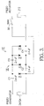
- System 10 for harvesting and utilizing waste energy to power an electrically operated door device such as a door release actuator in accordance with the present invention.
- System 10 comprises a device 12 such as a door release actuator 112; in one aspect of the invention, as described further herein, device 12 may be for example a low power consumption actuator, such as a piezoelectric actuator 212.
- a piezoelectric actuator 212 When piezoelectric actuator 212 is used to release a door latch, system 10 may be powered by a power management module 14 that powers a voltage booster 18 for increasing voltage to a level sufficient to energize piezoelectric actuator 212.
- Power management module 14 is responsive to a door-release authorization signal 20 and receives power from any waste energy harvester 22, such as, for example, RF or solar cell harvesters, or other known sources of waste energy as described above, or alternately from a piezoelectric energy harvester 24 which may be configured to harvest door motion energy or door or building vibration energy.
- any waste energy harvester 22 such as, for example, RF or solar cell harvesters, or other known sources of waste energy as described above, or alternately from a piezoelectric energy harvester 24 which may be configured to harvest door motion energy or door or building vibration energy.
- piezoelectric energy harvester 124 configured for releasing a door latch, may be incorporated into the hinge region of an electrically secured door for capturing the energy of any and all motion and vibration associated with the opening and closing of the door and other waste energy in the vicinity of the door available for capturing.
- a stepper motor generator 724 may be incorporated into the hinge region for capturing the energy associated with opening and closing the door.
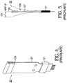
- piezo transducer 25 that may be used in piezo energy harvester 24 is preferably a Model M-8528-P2, available from Smart Materials Corp., Sarasota, Florida, USA, or a Model Volture V25w, available from Mide Technology Corp, Medford, Massachusetts, USA. Either of these devices develops a damped sinusoidal voltage output when strained in either direction and allowed to vibrate about a fixed end point. Referring to FIG.
- the damped sinusoid output from piezo transducer 25 is supplied to a schottky diode bridge rectifier (not shown), the output of which is used to charge a thin film battery (not visible) such as that found in micro power module (MPM) 14, preferably a Model D-MPM101, available from Infinite Power Solutions, Inc., Littleton, CO, USA.
- MPM micro power module
- MPM 14 has a regulated output voltage enable circuit which determines the period of time during which the battery is being drained as it supplies current to the voltage boosting circuit.
- Output energy from MPM 14 can be provided by something as simple as a switch, or by any set of contacts which are closed only after verification of credentials for the person desiring to enter the door.
- Another function provided by the MPM is to discontinue output voltage if the battery voltage has fallen to less than 60% of its fully charged voltage. Normally, this would never happen as it is the intent of this invention to keep the battery at or near full charge by applying more energy at the recharge inputs than the energy used by the piezo actuator and its control circuitry for each operation of the door.
- a piezo actuator such as piezoelectric actuator 212 needs voltage on the order of about 225 volts for proper operation.
- This voltage level is accomplished by employing a capacitor charge device 30 ( FIG. 2 ), preferably a Maxim Max 8622, available, for example, from Maxim, Sunnyvale, CA, USA, which converts a low voltage battery output to a voltage level needed by the piezo actuator.
- piezo cells for use in piezoelectric actuator 212 are available today.
- a Servo Cell AL2 available from ServoCell, Ltd., Harlow, UK, is found useful as it is a fully integrated unit that provides mechanical blocking of its linear displacement, permitting the piezo actuator to replace an electric solenoid in a slightly modified current production electric strike, as described below.
- Other piezo actuators such as the Mide Quick Pack qp2On, available from Mide, Inc., Medfor, MA, USA, may be used as a means of moving a blocking element to accomplish door unlocking.
- piezoelectric actuator 212 An interesting byproduct of the use of piezoelectric actuator 212 is that once charging of the piezo cell is complete and motion accomplished, it is possible to recapture a percentage of the energy expended in actuating the device by discharging the actuator's capacitance back into the DC charge input of the MPM. Theoretically, one can re-capture via recycle circuit 32 up to 60% of the original energy expended. Thus the actual power consumption of the piezoelectric actuator is substantially reduced.
- the electronic circuitry used to capture the harvested energy and use it to power the piezoelectric actuator consists of two elements - the MPM 14, and voltage booster 18.
- MPM 14 contains three connectors, J2, J3 and J5. The first two are used to recharge the battery from DC and AC sources respectively.
- J2 collects recycled energy 34 from the discharge of piezoelectric actuator 212.
- J3 may be used to collect additional waste energy from a variety of waste energy sources including, for example, collected RF energy 28a and collected solar energy 28b.
- J3 takes the harvested door motion energy via output 36. Since energy recoverable from door motion is readily available, it is the primary source of harvested waste energy to recharge the battery.
- Connector J5 is used for input and output signals.
- Pins 1 and 2 provide under voltage protection to ensure that the battery output never drops below 2.1 volts.
- Pins 3 and 4 receive enabling signals for the regulated 3.6 volt output provided at pin 7.
- Pin 5 is an isolated ground that does not connect directly to the ground of the internal thin film battery.
- the output voltage from pin 7 MPM 14 provides a low voltage, such as 3.6 volts.
- Capacitors C5 and CI filter some of the noise signal created by the switching regulator in the voltage booster.
- Voltage booster 18 includes a charge device that uses a switching regulator and output transformer to boost an input voltage to an output voltage, for example 200 v. to 250 v., which is needed by the piezoelectric actuator 212.
- Resistor R2 sets the output level which the unit is trying to achieve.
- Resistor R1 establishes the maximum input draw for the unit which is set as low as possible.
- Diodes D1 and D2 ensure that no back current is supplied to voltage booster 18 when the piezo actuator is discharging.
- Diode D3 and resistor R6 limit the current which can be fed back to recharge the battery through the DC charging input J2.
- Switch 38 designated SW1, applies the re-captured voltage to the battery after the unlock pushbutton is released.
- the timing sequence is then:
- System 10' comprises a piezo harvester, such as for example piezoelectric energy harvester 124, a voltage boost circuit 18', an operating switch SW1 38', and a piezoelectric actuator 212.
- Voltage boost circuit 18' is preferably a Greinacher-type circuit comprising a plurality of capacitors and diodes as is known in the prior art to boost the harvester output to the voltage potential required to drive the piezoelectric actuator 212.
- a battery and control circuitry as shown in FIG. 2 are required to accumulate waste kinetic energy as it occurs and to energize actuator 212.
- Transducer 25 may be used in piezoelectric energy harvester 24,124. This device converts vibration into electrical energy when the ballast 125, mounted on base plate 127 which also contains the piezo device, is flexed in either direction from the rest position 129. Transducer 25 has good elastic attributes that allow it to deflect 131 from center up to about 0.25 inches on either side of rest position 129.
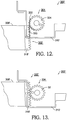
- Mechanical actuator assembly 200 comprises a base plate 202 and stanchion 204 for rotatably supporting a rotatable actuating sprocket assembly 206.
- Sprocket assembly 206 comprises a yoke 208 mounted on a shaft 210 journalled in stanchion 204 and includes a plurality of actuators 211, exemplarily four, mounted for both pivoting and translating in yoke 208 as described below.
- Each actuator 211 is provided with a rounded nose 214, rides in a first radial slot 216 formed in yoke 208, and is pivotably pinned by a pin 218 into a second slot 220 formed in yoke 208. Each actuator 211 captures a bias spring 222 in second slot 220 such that each actuator is urged after perturbation to return to a rest position 224 as shown in FIG. 8 .
- each actuator 211 during rotation of sprocket assembly 206 and sequential engaging with, and disengaging from, ballast 125 of a piezoelectric energy harvester 124 is free to move rotationally on pin 218 in either direction ( FIGS. 6 and 7 ) and to move translationally radially in first and second slots 216,220 in response to being perturbed by rotation of assembly 206 in either direction as described below.
- a first piezoelectric energy harvester system 300 in accordance with the present invention comprises an energy input portion 302 and an energy harvesting portion 304.
- Energy input portion 302 comprises a door hinge 306 mountable to a door 308 in door frame 310 to cause the door 308 to swing in the frame 310.
- a hinge pin 312 extends beyond the leaves 314,316 of hinge 306 and fixedly supports a drive member such as a hinge pin spur gear 318.
- Hinge pin 312 is attached to the door-mounting leaf 316 of hinge 306 such that pin 312 and gear 318 remain fixed and stationary with respect to door 308 but rotate about hinge pivot axis 320 when door 308 is swung on hinge 306.
- Energy harvesting portion 304 comprises a piezoelectric energy harvester 124 as shown in FIGS. 4 and 5 mounted via a bracket 322 to base plate 202 of a mechanical actuator assembly 200.
- Mechanical actuator assembly 200 comprises base plate 202 and first and second stanchions 204 for rotatably supporting a rotatable sprocket assembly 206.
- Sprocket assembly 206 comprises first and second yokes 208 fixedly mounted on a shaft 210 journalled in stanchions 204.
- First and second yokes 208 are opposed on shaft 210 and are crenellated to be mutually out of phase by 45[deg.] such that sprocket assembly 206 provides 8 actuators 211 for engaging harvester ballast 125.
- Shaft 208 extends beyond stanchion 204 to support a driven member such as capture (pinion) gear 324 meshed with hinge pin (spur) gear 318.
- Energy harvesting portion 304 defines an energy harvesting module that preferably includes a cover (not shown) for protecting harvester 124 and subassembly 206 from the environment, as well as to reduce the noise of engagement of the gears and the actuators with the ballast.
- piezoelectric energy harvester system 300 An advantage of piezoelectric energy harvester system 300 is that the driver/driven ratios may be selected to maximize energy harvest for a particular application. Further, the mass of ballast 125 may be selected to match the anticipated door velocity and thus optimize the resonance periods between ballast/actuator engagements to maximize energy output of harvester 124.
- Energy input portion 302 is mounted to an edge of door 308, and energy harvesting portion 304 is mounted within a hollow frame 310 which is slotted 326 to provide access for gear 318 to gear 324. Energy is captured by harvester 124 during opening and closing motions of the door in the frame.
- a second piezoelectric energy harvester system 300' in accordance with the present invention comprises an energy input portion 302' and the energy harvesting portion 304 described above. Only capture pinion gear 324 of portion 304 is shown.
- System 300' harvests kinetic energy from the door-latch side of a door 308' mounted in a hollow frame 310', as opposed to embodiment 300 which harvests energy from the hinge side.
- energy harvesting portion 304 is mounted within frame 310', and energy input portion 302' includes a drive member such as linear rack gear 318' mounted to the beveled edge of door 308' for engaging the driven member (pinion gear 324) to drive energy harvesting portion 304 as in the first system embodiment 300. It will be seen that energy is harvested both in opening and in closing door 308'.
- drive gears 318, 318' can be replaced with friction wheels having, for example, a resilient contact surface 330 and driven gears 324, 324' can be replaced with a friction wheel or a friction rack having, for example, a mating resilient surface 332.
- sprocket assembly 206 may be simply a wheel having a select number of radial teeth for making contact with ballast 125.
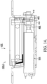
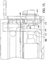
- an electric strike portion 400-2 of an electric door strike system comprises an electric strike 402, for example, a Model 5000 available from Hanchett Entry Systems, Inc., Phoenix, AZ, USA, modified as described below to include a piezoelectric actuator 212 in place of a standard linear electric solenoid (not shown). For simplicity and clarity, only the mounting and actuation portion of strike 402 are shown.
- Strike 402 comprises a formed metal frame 404 supporting piezoelectric actuator 212 having a shaft 406 extending longitudinally therefrom.
- Shaft 406 includes an actuation portion 408 extending through a linear bearing 410 mounted in frame 404.
- Actuation portion 408 includes a collar 412 to limit axial motion of shaft 406 away from actuator 212 by engagement with a support bracket 414 also mounted on frame 404.
- Actuation portion 408 further includes an annular groove 416 having a beveled side defining a shaft engagement slope 418 for receiving a keeper 420 having a mating engagement slope 422.
- Keeper 420 is a blocking link in the linkage releasing or locking a latch (not shown) in strike 402.
- keeper 420 includes pivot hole 424 for mounting to strike 402 and an arcuate slot 426 concentric with the axis of pivot hole 424.
- the lands on either side of slot 426 are tapered to form engagement slope 422 as shown in FIGS. 15 and 16 .
- shaft 406 is shown in the blocking position wherein keeper 420 blocks the linkage from activating to unlock the latch.
- Shaft 406 is biased to the right in FIG. 15 by one or more bias springs (not visible).
- the shaft bias springs are sufficiently powerful that, in combination with the de-energized piezo cell, the keeper is maintained in the locking position against a latch-opening force sufficient to resist unwanted unlocking of the lock, as for example, up to at least 1000 pounds of latch-opening force.
- the piezo cell in actuator 212 When the piezo cell in actuator 212 is energized, the cell actuates a blocking element, permitting shaft 406 to move to the left, allowing keeper 420 to rotate to move groove 416 farther into slot 426, in which position keeper 420 no longer blocks the linkage and the latch is thus unlocked.
- a relatively small manual force applied to the latch as by a person attempting to open the door is sufficient to displace the shaft to the left and allow the keeper to be forced into the unlocking position by engagement of the engagement slopes 418,422.
- an exemplary, prior art handle-lock set 500 for example, a commercially available key-in-knob-lock, comprises a hub 502 having first and second connecting posts 504 extending therefrom for receiving screws (not shown) extending through a door and bezel (not shown).
- a locking shaft 506 and latch engaging shaft 508 extend through an opening in hub 502.
- Locking shaft 506 is connected to key 530 but is turnable independently of latch engaging shaft 508 which is attached to knob 509.
- Cooperative with locking shaft 506 is a floating locking tab 510 having spaced-apart first and second locking tangs 512,514 straddling upper connecting post 504 within locking ring 515. As shown below in FIG.
- a cam plate 516 having an angled slot 518 is mounted to locking shaft 506.
- a pin 520 attached to locking tab 510 extends through slot 518.
- Slot 518 is formed such that upon rotation of locking shaft 506 (clockwise in FIG. 21 ; counterclockwise in FIG. 17 ), locking tab 510 is moved inwardly along a radius of hub 502 until tangs 512/514 no longer straddle connecting post 504 and can clear locking ring 515, permitting knob 509 and latch engaging shaft 508 to be rotated, thereby actuating a door latch (not shown) to open the door (not shown).
- floating locking tab 510 is modified to define a novel floating locking tab 610.
- Prior art tang 512 is retained, but prior art tang 514 is replaced by assembly 623 comprising a piezoelectric actuator 622 and a domed plunger 624.
- Locking ring 515 is modified to define a novel locking ring 615 having a ramp 626 for engaging domed plunger 624 in the locked state.
- Piezoelectric actuator 622 is preferably of the type AL-2, available from Servocell Ltd., Harlow, UK.
- the locked state may be overridden in one of three ways: by energizing of actuator 622, by rotation of key 530 or the use of thumb turn, not shown.
- handle/knob 509 when piezoelectric actuator 622 is energized, handle/knob 509 may be turned in one direction (unidirectional) to open the door despite the door's being mechanically key-locked. In its un-energized state, piezoelectric actuator 622 remains rigid with domed plunger 624 extended as shown in FIG. 18 . Energizing of actuator 622 removes rigid support for plunger 624. Torque on handle/knob 509 ( FIG. 19 ), locking shaft 506, and floating tab 610 urges the dome of plunger 624 against ramp 626, causing plunger 624 to be forced into assembly 623. When the plunger has cleared the ramp, tab 610 may be turned as shown, unlocking the mechanism.
- handle/knob 509 can be turned in only one direction to act against piezo actuator 622. Turning the handle/knob in the other rotational direction, even with piezoelectric actuator 622 energized, will cause locking tang 512 and rotation of knob 509 to be blocked by post 504.
- locking tang 512 may be replaced with a second piezo actuator assembly 623 and ring 615 may be further modified with a second mirror-imaged ramp 626 on the opposite side of post 504.
- handle/knob 509 may be turned in either rotational direction (bi-directional) to open the door upon energizing the actuators despite the door's being mechanically key locked.
- handle-lock set 600 may also be unlocked conventionally by the key. As described above, when key 530 and locking shaft 506 are turned, cam plate 516 urges tab 610 radially inwards of hub 502 such that tang 512 and plunger 624, or a pair of plungers 624, no longer straddle connecting post 504 ( FIG. 23 ), allowing latch engaging shaft 508 to be rotated ( FIG. 24 ).
- FIGS. 25 through 27 a further embodiment 700 of an energy harvester is shown.
- a stationary drive member such as drive gear 718 is mounted to a fixed hinge pin 712 of a door hinge 702 mounted on a frame 710.
- An energy harvester mounted on a door 308 in the form of a stepper motor/generator 724 is provided with a driven member such as pinion gear 704 in meshing relationship with drive gear 718.
- a driven member such as pinion gear 704 in meshing relationship with drive gear 718.
- pinion gear 704 is rotated causing lobes of the magnetic rotor (not visible) of stepper motor/generator 724 to serially pass by and excite the coils (not visible) within the stepper motor in known fashion, generating an output series of two-phase sinusoidal signals along wire leads 726 that may be captured as stored electrical energy by the thin film battery in power management module 14 ( FIGS. 1 and 2 ).
- the sinusoidal signals are rectified by passage through a pair of bridge rectifiers 730 shown in FIG. 29 . attached to the DC charging input of MPM 14 at connector J2 ( FIG. 2 ).
- drive gear 718 can be replaced with a friction wheel having, for example, a resilient contact surface 730 and driven gear 704 can be replaced with a friction wheel having, for example, a mating resilient surface 732 ( FIG. 26 ).
- a door 308 such as for example a Rite Door manufactured by Adams Rite Co. Pomona, Ca
- an energy harvester exemplarily a stepper motor/generator 724
- a micro power module 14 as described above
- a piezoelectric door lock exemplarily a key-in-the-knob lock set 600 as shown in FIGS. 18-24 . While stepper motor/generator 724 is shown exposed through surface 309 of door 308, it is understood that motor/generator 724 and interconnecting wires may be completely confined between opposing door surfaces 309, 311 ,of the exemplary door so that motor/generator 724 is not readily visible or readily accessible from either surfaces.
Landscapes
- Engineering & Computer Science (AREA)
- Mechanical Engineering (AREA)
- Civil Engineering (AREA)
- Structural Engineering (AREA)
- General Electrical Machinery Utilizing Piezoelectricity, Electrostriction Or Magnetostriction (AREA)
- Lock And Its Accessories (AREA)
Claims (11)
- System zum Betätigen einer elektrischen Vorrichtung (12, 112, 212), die mit einer Tür oder einem Verschluss (308; 308') assoziiert ist, wobei das System Folgendes aufweist:a) einen piezoelektrischen Energieaufnehmer (124), der fähig ist, Energie aufzunehmen, indem der piezoelektrische Energieaufnehmer (124) relativ zu einer Ruheposition (129) erregt wird,b) eine mechanische Betätigungsanordnung (200), um den piezoelektrischen Energieaufnehmer (124) zu betätigen, wobei die mechanische Betätigungsanordnung (200) einen Ritzelteil (206) aufweist, der konfiguriert ist, um sich zu drehen, wenn die Tür sich relativ zu einem Türrahmen bewegt, wobei der Ritzelteil (206) konfiguriert ist, um einen Kontakt mit dem piezoelektrischen Energieaufnehmer (124) herzustellen, und wobei der piezoelektrische Energieaufnehmer (124) durch den Kontakt erregt wird,wobei die Vorrichtung (12, 112, 212) elektrische Energie von dem piezoelektrischen Energieaufnehmer (124) aufnimmt, und wobei zumindest ein Teil der elektrischen Energie verwendet wird, um die Vorrichtung (12, 112, 212) zu betätigen.
- System nach Anspruch 1, welches weiter eine Spannungsverstärkungsschaltung (18) aufweist, die betriebsmäßig mit dem piezoelektrischen Energieaufnehmer (124) verbunden ist, und optional weiter ein Leistungs-modul (14) aufweist, welches eine Batterie aufweist, die in einer Schaltung zwischen dem piezoelektrischen Energieaufnehmer (124) und der Spannungsverstärkungsschaltung (18) angeordnet ist und/oder wobei die Vorrichtung eine piezoelektrische Betätigungsvorrichtung (212) ist und weiter eine Betätigungsvorrichtungsentladeschaltung (32) aufweist, die zwischen der piezoelektrischen Betätigungsvorrichtung (212) und der Batterie angeordnet ist, um einen Teil der elektrischen Energie zu recyceln, die verwendet wird, um die Betätigungsvorrichtung zu bewegen.
- System nach einem der vorhergehenden Ansprüche, wobei die Vorrichtung eine piezoelektrische Betätigungsvorrichtung (212) ist und/oder wobei die Vorrichtung aus der Gruppe ausgewählt ist, die aus einer Beleuchtungsvorrichtung, einer Tastatur und einer Videoanzeige besteht.
- System nach einem der vorhergehenden Ansprüche, wobei der piezoelektrische Energieaufnehmer (124) einen Energieeingabeteil (302) und einen Energieaufnahmeteil (304) aufweist, wobei der Energieeingabeteil (302) optional ein Eingabeglied (318) aufweist, welches so konfiguriert ist, dass es durch eine Bewegung der Tür betätigbar ist, und wobei der Energieaufnahmeteil (304) optional ein Aufnahmeglied (324) aufweist, welches ausgebildet ist, um eine mechanische Eingabe von dem Eingabeglied (318) aufzunehmen, und konfiguriert ist, um den Energieaufnahmeteil (304) zu erregen.
- System nach Anspruch 4, wobei das Energieeingabeglied (318) ein Zahnrad aufweist, insbesondere eine Zahnstange (318'), oder
wobei das Eingabeglied (318) ein Antriebsglied ist, und wobei das Aufnahmeglied (324) ein angetriebenes Glied ist,
wobei das Aufnahmeglied (324) optional einen Ritzelteil (206) aufweist, der zur Bewegung mit dem Aufnahmeglied (324) angeordnet ist, wobei der Ritzelteil konfiguriert sein kann, um einen Kontakt mit dem piezoelektrischen Energieaufnehmer (124) herzustellen, und wobei der piezoelektrische Energieaufnehmer (124) durch den Kontakt erregt werden kann. - System nach Anspruch 5, wobei der Ritzelteil (206) zumindest eine radial angeordnete Betätigungsvorrichtung (211) aufweist, um einen Kontakt mit dem piezoelektrischen Energieaufnehmer (124) herzustellen,
wobei die mindestens eine radial angeordnete Betätigungsvorrichtung (211) optional bewegbar mit dem Ritzelteil (206) verbunden ist. - System nach Anspruch 1, wobei die mechanische Betätigungsanordnung (200) weiter zumindest eine radial angeordnete Betätigungsvorrichtung (211) aufweist, um einen Kontakt mit dem piezoelektrischen Energieaufnehmer (124) herzustellen.
- System nach Anspruch 7, wobei die mindestens eine radial angeordnete Betätigungsvorrichtung (211) bewegbar mit dem Ritzelteil (206) verbunden ist.
- System nach Anspruch 7, wobei die mechanische Betätigungsanordnung (200) weiter eine Vorspannfeder (222) aufweist, die zwischen der mindestens einen radial angeordneten Betätigungsvorrichtung (211) und dem Ritzelteil (206) angeordnet ist.
- System nach Anspruch 1, wobei der piezoelektrische Energieaufnehmer (124) eine Basisplatte (127) mit ersten und zweiten Enden aufweist, wobei das erste Ende ein Ballastelement (125) aufweist, welches relativ zum zweiten Ende cantileverartig bzw. vorstehend aufgehängt ist.
- System nach Anspruch 1, wobei der piezoelektrische Energieaufnehmer (124) in einem Scharnierbereich der Tür und des Türrahmens angeordnet werden kann.
Applications Claiming Priority (1)
| Application Number | Priority Date | Filing Date | Title |
|---|---|---|---|
| US32469810P | 2010-04-15 | 2010-04-15 |
Publications (3)
| Publication Number | Publication Date |
|---|---|
| EP2378041A2 EP2378041A2 (de) | 2011-10-19 |
| EP2378041A3 EP2378041A3 (de) | 2013-09-25 |
| EP2378041B1 true EP2378041B1 (de) | 2017-01-04 |
Family
ID=44359749
Family Applications (1)
| Application Number | Title | Priority Date | Filing Date |
|---|---|---|---|
| EP11003216.6A Active EP2378041B1 (de) | 2010-04-15 | 2011-04-15 | Elektrische Türfreigabe, die von einem Energiesammler angetrieben wird |
Country Status (3)
| Country | Link |
|---|---|
| US (4) | US9151079B2 (de) |
| EP (1) | EP2378041B1 (de) |
| CA (3) | CA2737673C (de) |
Families Citing this family (58)
| Publication number | Priority date | Publication date | Assignee | Title |
|---|---|---|---|---|
| US9260882B2 (en) | 2009-03-12 | 2016-02-16 | Ford Global Technologies, Llc | Universal global latch system |
| CA2737673C (en) * | 2010-04-15 | 2019-06-25 | Hanchett Entry Systems, Inc. | Electric door release powered by an energy harvester |
| US8643999B2 (en) * | 2010-08-17 | 2014-02-04 | Electronics And Telecommunications Research Institute | Electromagnetic interference reduction apparatus |
| JP2013070520A (ja) * | 2011-09-22 | 2013-04-18 | Panasonic Corp | 非接触給電装置の駆動方法、非接触給電装置及び非接触給電システム |
| US9551166B2 (en) | 2011-11-02 | 2017-01-24 | Ford Global Technologies, Llc | Electronic interior door release system |
| US9431927B2 (en) * | 2012-05-07 | 2016-08-30 | Xceedid Corporation | System for harvesting energy from door or door hardware movement |
| CA2873273C (en) * | 2012-05-08 | 2020-07-21 | Schlage Lock Company Llc | Door closer system |
| US10008660B2 (en) * | 2012-12-14 | 2018-06-26 | Meggitt A/S | Generator unit for energy harvesting with a single force input point |
| US9913321B2 (en) * | 2013-01-25 | 2018-03-06 | Energyield, Llc | Energy harvesting container |
| US9728017B2 (en) | 2013-03-01 | 2017-08-08 | Yves Paquin | Electronic door access control system |
| CN105324865B (zh) | 2013-03-12 | 2017-11-17 | 品谱股份有限公司 | 具有多源能量收集回路的电子锁具 |
| WO2015047236A1 (en) | 2013-09-25 | 2015-04-02 | Schneider Electric USA, Inc. | Spring loaded, bistable connect/disconnect for mcc unit |
| WO2015047307A1 (en) | 2013-09-27 | 2015-04-02 | Schneider Electric USA, Inc. | Motor control center unit disconnect with interlocks |
| CA2922271C (en) | 2013-09-30 | 2020-11-03 | Schneider Electric USA, Inc. | Mcc unit troubleshooting compartment |
| DK178090B1 (da) * | 2013-10-22 | 2015-05-11 | Bekey As | Elektrisk slutblik-system |
| US9865997B2 (en) | 2013-11-12 | 2018-01-09 | Schneider Electric USA, Inc. | Double shutter shroud and tunnel for MCC bus connections |
| US9416565B2 (en) | 2013-11-21 | 2016-08-16 | Ford Global Technologies, Llc | Piezo based energy harvesting for e-latch systems |
| US9435142B2 (en) | 2014-02-28 | 2016-09-06 | Schlage Lock Company Llc | Method of operating an access control system |
| DE102014205720A1 (de) | 2014-03-27 | 2015-10-01 | Zf Friedrichshafen Ag | Vorrichtung für eine Betätigungshandhabe, Betätigungshandhabe und Verfahren zur drahtlosen Übermittlung eines energieautark erzeugten Signals |
| WO2015152874A1 (en) | 2014-03-31 | 2015-10-08 | Schneider Electric USA, Inc. | Live load indicator with door interlock |
| US9903142B2 (en) | 2014-05-13 | 2018-02-27 | Ford Global Technologies, Llc | Vehicle door handle and powered latch system |
| US10273725B2 (en) | 2014-05-13 | 2019-04-30 | Ford Global Technologies, Llc | Customer coaching method for location of E-latch backup handles |
| US10323442B2 (en) | 2014-05-13 | 2019-06-18 | Ford Global Technologies, Llc | Electronic safe door unlatching operations |
| US10119308B2 (en) | 2014-05-13 | 2018-11-06 | Ford Global Technologies, Llc | Powered latch system for vehicle doors and control system therefor |
| US9748024B2 (en) | 2014-06-20 | 2017-08-29 | Schneider Electric USA, Inc. | Passive arc control with sequestered phases in a vertical bus system of a motor control center |
| US9909344B2 (en) | 2014-08-26 | 2018-03-06 | Ford Global Technologies, Llc | Keyless vehicle door latch system with powered backup unlock feature |
| US10438978B2 (en) | 2014-10-31 | 2019-10-08 | Sargent Manufacturing Company | Measuring harvested energy using an ultra-low duty cycle measurement system |
| US10128283B2 (en) | 2014-10-31 | 2018-11-13 | Sargent Manufacturing Company | Method and system for managing harvested energy in an access control system |
| US20160138301A1 (en) * | 2014-11-14 | 2016-05-19 | The Boeing Company | Self-contained electronic stowage bin system |
| US9725069B2 (en) | 2015-10-12 | 2017-08-08 | Ford Global Technologies, Llc | Keyless vehicle systems |
| RU2616907C1 (ru) * | 2016-04-25 | 2017-04-18 | Никишин ГмбХ | Узел дверной ручки |
| US10227810B2 (en) | 2016-08-03 | 2019-03-12 | Ford Global Technologies, Llc | Priority driven power side door open/close operations |
| US10087671B2 (en) | 2016-08-04 | 2018-10-02 | Ford Global Technologies, Llc | Powered driven door presenter for vehicle doors |
| US10243136B2 (en) | 2016-08-22 | 2019-03-26 | Masoud Ghanbari | Piezoelectric energy harvesting system from vehicle's tires |
| US10329823B2 (en) | 2016-08-24 | 2019-06-25 | Ford Global Technologies, Llc | Anti-pinch control system for powered vehicle doors |
| US10458171B2 (en) | 2016-09-19 | 2019-10-29 | Ford Global Technologies, Llc | Anti-pinch logic for door opening actuator |
| DE102017102599A1 (de) | 2017-02-09 | 2018-08-09 | Efaflex Tor- Und Sicherheitssysteme Gmbh & Co. Kg | Tor mit einem intelligenten Torblatt, welches eine elektrisch autarke Torblatteinrichtung aufweist, sowie Verfahren hierfür |
| US10551881B2 (en) * | 2017-03-17 | 2020-02-04 | Microsoft Technology Licensing, Llc | Thermal management hinge |
| US10704294B1 (en) | 2017-04-17 | 2020-07-07 | Lockheed Martin Corporation | Wirelessly actuated cover for a structure |
| US10604970B2 (en) | 2017-05-04 | 2020-03-31 | Ford Global Technologies, Llc | Method to detect end-of-life in latches |
| EP3654486B1 (de) * | 2017-07-13 | 2023-03-08 | Panasonic Intellectual Property Management Co., Ltd. | Energieerzeugungssystem und stromversorgungssystem |
| DE102017213589A1 (de) * | 2017-08-04 | 2019-02-07 | Skf Lubrication Systems Germany Gmbh | Schmiersystem mit einem Signalübertragungselement |
| DE102017213588A1 (de) * | 2017-08-04 | 2019-02-07 | Skf Lubrication Systems Germany Gmbh | Schmiersystem mit einem Energieerzeugungselement |
| US11131132B2 (en) * | 2017-09-28 | 2021-09-28 | Ergomat, Inc. | Gate supportive, signal transmitting hinge |
| US10774576B1 (en) * | 2017-10-20 | 2020-09-15 | Ameristar Perimeter Security Usa Inc. | Gate assembly |
| CN107939194A (zh) * | 2017-12-28 | 2018-04-20 | 长沙理工大学 | 一种发电门铰链 |
| DE102018110608B4 (de) * | 2018-05-03 | 2025-07-03 | Kiekert Aktiengesellschaft | Kraftfahrzeug-Antriebsanordnung |
| US10907386B2 (en) | 2018-06-07 | 2021-02-02 | Ford Global Technologies, Llc | Side door pushbutton releases |
| US10439371B1 (en) | 2018-06-22 | 2019-10-08 | Schneider Electric USA, Inc. | Snapped in rotating arc housing assembly for safety switch |
| US20200136425A1 (en) * | 2018-10-24 | 2020-04-30 | Semiconductor Components Industries, Llc | Wireless communication system and method powered by an energy harvester |
| DE102018126690A1 (de) * | 2018-10-25 | 2020-04-30 | Eldat Gmbh | Vorrichtung zur Energiegewinnung zur Verwendung an einer Tür oder einem Fenster sowie Sensor |
| DE102018218596B4 (de) | 2018-10-30 | 2020-06-04 | Conti Temic Microelectronic Gmbh | Verfahren zum Laden einer Starterbatterie sowie Ladevorrichtung zum Laden einer Starterbatterie |
| US11639617B1 (en) | 2019-04-03 | 2023-05-02 | The Chamberlain Group Llc | Access control system and method |
| US11613918B2 (en) * | 2019-04-04 | 2023-03-28 | Stmicroelectronics S.R.L. | Door unlock mechanism |
| US12331560B2 (en) * | 2019-06-17 | 2025-06-17 | Trimark Corporation | Motor control for powered closure with anti-pinch |
| SE544107C2 (en) | 2019-06-27 | 2021-12-28 | Assa Abloy Ab | Arrangement for electronic locking system with energy harvesting and feedback, and electronic locking system |
| CN118140375A (zh) | 2021-09-23 | 2024-06-04 | 麦森尼特公司 | 具有可再充电电池的门组件、用于对电池充电的方法和系统 |
| CN116231947B (zh) * | 2023-03-17 | 2024-04-16 | 国网江苏省电力有限公司电力科学研究院 | 适用于输电线路的能量收集装置及自供能振动监测装置 |
Citations (1)
| Publication number | Priority date | Publication date | Assignee | Title |
|---|---|---|---|---|
| EP1314838A1 (de) * | 2001-11-21 | 2003-05-28 | ArvinMeritor Light Vehicle Systems (UK) Ltd | Gerät zur Speicherung von Energie |
Family Cites Families (10)
| Publication number | Priority date | Publication date | Assignee | Title |
|---|---|---|---|---|
| DE3208818C2 (de) * | 1982-03-11 | 1985-11-07 | Fa. Aug. Winkhaus, 4404 Telgte | Elektrisch entriegelbares Schloß mit lokaler Stromversorgung und piezoelektrischem Blockierriegel |
| DE20220187U1 (de) * | 2002-12-23 | 2003-04-17 | Schneider + Fichtel GmbH, 72108 Rottenburg | Türeinrichtung für Gebäuderäume |
| JP2004204533A (ja) * | 2002-12-25 | 2004-07-22 | Mitsubishi Electric Engineering Co Ltd | 扉開閉装置 |
| DE102005022930A1 (de) | 2005-05-15 | 2006-11-16 | Gunter Kries | Kontaktzustandsabhängiges Verriegelungssystem |
| US7522042B2 (en) * | 2006-05-18 | 2009-04-21 | T.K.M. Unlimited, Inc. | Door accessory power system |
| DE102007032855A1 (de) | 2007-07-12 | 2009-01-22 | Karl-Heinz Bosch | Verfahren und Vorrichtung zur Erzeugung von elektrischer Energie an beweglichen Bauelementen |
| US7667371B2 (en) * | 2007-09-17 | 2010-02-23 | Motorola, Inc. | Electronic device and circuit for providing tactile feedback |
| US8274383B2 (en) * | 2008-03-31 | 2012-09-25 | The Boeing Company | Methods and systems for sensing activity using energy harvesting devices |
| US7795746B2 (en) | 2008-05-01 | 2010-09-14 | Robert Bosch Gmbh | Apparatus and method for generating power for a low current device |
| CA2737673C (en) * | 2010-04-15 | 2019-06-25 | Hanchett Entry Systems, Inc. | Electric door release powered by an energy harvester |
-
2011
- 2011-04-15 CA CA2737673A patent/CA2737673C/en active Active
- 2011-04-15 CA CA3042643A patent/CA3042643C/en active Active
- 2011-04-15 CA CA3117197A patent/CA3117197A1/en active Pending
- 2011-04-15 EP EP11003216.6A patent/EP2378041B1/de active Active
- 2011-04-15 US US13/087,653 patent/US9151079B2/en active Active
-
2015
- 2015-10-05 US US14/875,070 patent/US10270372B2/en active Active
-
2018
- 2018-10-30 US US16/175,167 patent/US10615721B2/en active Active
-
2020
- 2020-02-27 US US16/802,919 patent/US11658588B2/en active Active
Patent Citations (1)
| Publication number | Priority date | Publication date | Assignee | Title |
|---|---|---|---|---|
| EP1314838A1 (de) * | 2001-11-21 | 2003-05-28 | ArvinMeritor Light Vehicle Systems (UK) Ltd | Gerät zur Speicherung von Energie |
Also Published As
| Publication number | Publication date |
|---|---|
| US10615721B2 (en) | 2020-04-07 |
| CA3042643C (en) | 2023-01-24 |
| US20110252845A1 (en) | 2011-10-20 |
| EP2378041A3 (de) | 2013-09-25 |
| EP2378041A2 (de) | 2011-10-19 |
| US20200195171A1 (en) | 2020-06-18 |
| CA3042643A1 (en) | 2011-10-15 |
| CA2737673C (en) | 2019-06-25 |
| CA3117197A1 (en) | 2011-10-15 |
| CA2737673A1 (en) | 2011-10-15 |
| US9151079B2 (en) | 2015-10-06 |
| US20160028329A1 (en) | 2016-01-28 |
| US11658588B2 (en) | 2023-05-23 |
| US20190068085A1 (en) | 2019-02-28 |
| US10270372B2 (en) | 2019-04-23 |
Similar Documents
| Publication | Publication Date | Title |
|---|---|---|
| EP2378041B1 (de) | Elektrische Türfreigabe, die von einem Energiesammler angetrieben wird | |
| US8851530B2 (en) | Electric latch retraction bar | |
| US7522042B2 (en) | Door accessory power system | |
| RU2484224C2 (ru) | Система запирания с использованием микродвигателя | |
| US7952477B2 (en) | Door lock assembly | |
| EP3533955B1 (de) | Elektronisches schliesssystem mit energiegewinnungsanordnung | |
| HK1208512A1 (en) | Inline motorized lock drive for solenoid replacement | |
| US20180298639A1 (en) | No-fail smart lock | |
| CA2257935A1 (en) | Electronic locking device | |
| KR102757848B1 (ko) | 전자식 잠금 시스템용 장치 및 전자식 잠금 시스템 | |
| DE19755620A1 (de) | Fernbedienung | |
| EP1564689A2 (de) | Vorrichtung zum Betätigen eines Schlosses mit einer Not-Einrichtung zum Entsichern und/oder Sichern des Schlosses | |
| TW202311609A (zh) | 便攜式電子鎖 | |
| DE102012017820A1 (de) | Verfahren und Vorrichtung zum Betrieb eines Schrankschlosses einer zentralen Schließanlage mit Energiegewinnung | |
| DE102011108268B4 (de) | Elektronischer Türöffner | |
| RU238881U1 (ru) | Электронный замок | |
| WO2009028991A2 (en) | Mechanically locking or blocking electronic device | |
| KR200493472Y1 (ko) | 락카용 디지털 잠금장치 | |
| US20240088750A1 (en) | Door leaf assembly with fittings equipped with an add-on module for autonomous power supply | |
| RU2040680C1 (ru) | Электромеханический кодовый замок | |
| JP2014234634A (ja) | ドア扉錠作動用電気シリンダの安全装置 | |
| WO2007069938A1 (en) | Lock | |
| WO2001026204A1 (en) | Kinetomatic system |
Legal Events
| Date | Code | Title | Description |
|---|---|---|---|
| AK | Designated contracting states |
Kind code of ref document: A2 Designated state(s): AL AT BE BG CH CY CZ DE DK EE ES FI FR GB GR HR HU IE IS IT LI LT LU LV MC MK MT NL NO PL PT RO RS SE SI SK SM TR |
|
| AX | Request for extension of the european patent |
Extension state: BA ME |
|
| PUAI | Public reference made under article 153(3) epc to a published international application that has entered the european phase |
Free format text: ORIGINAL CODE: 0009012 |
|
| RIC1 | Information provided on ipc code assigned before grant |
Ipc: E05B 47/00 20060101AFI20130429BHEP Ipc: H02K 57/00 20060101ALI20130429BHEP |
|
| PUAL | Search report despatched |
Free format text: ORIGINAL CODE: 0009013 |
|
| AK | Designated contracting states |
Kind code of ref document: A3 Designated state(s): AL AT BE BG CH CY CZ DE DK EE ES FI FR GB GR HR HU IE IS IT LI LT LU LV MC MK MT NL NO PL PT RO RS SE SI SK SM TR |
|
| AX | Request for extension of the european patent |
Extension state: BA ME |
|
| RIC1 | Information provided on ipc code assigned before grant |
Ipc: E05B 47/00 20060101AFI20130819BHEP Ipc: H02K 57/00 20060101ALI20130819BHEP |
|
| 17P | Request for examination filed |
Effective date: 20140325 |
|
| RBV | Designated contracting states (corrected) |
Designated state(s): AL AT BE BG CH CY CZ DE DK EE ES FI FR GB GR HR HU IE IS IT LI LT LU LV MC MK MT NL NO PL PT RO RS SE SI SK SM TR |
|
| 17Q | First examination report despatched |
Effective date: 20150327 |
|
| GRAP | Despatch of communication of intention to grant a patent |
Free format text: ORIGINAL CODE: EPIDOSNIGR1 |
|
| RIC1 | Information provided on ipc code assigned before grant |
Ipc: H02N 2/18 20060101ALI20160620BHEP Ipc: E05B 47/00 20060101AFI20160620BHEP |
|
| INTG | Intention to grant announced |
Effective date: 20160722 |
|
| GRAS | Grant fee paid |
Free format text: ORIGINAL CODE: EPIDOSNIGR3 |
|
| GRAA | (expected) grant |
Free format text: ORIGINAL CODE: 0009210 |
|
| AK | Designated contracting states |
Kind code of ref document: B1 Designated state(s): AL AT BE BG CH CY CZ DE DK EE ES FI FR GB GR HR HU IE IS IT LI LT LU LV MC MK MT NL NO PL PT RO RS SE SI SK SM TR |
|
| REG | Reference to a national code |
Ref country code: GB Ref legal event code: FG4D |
|
| REG | Reference to a national code |
Ref country code: CH Ref legal event code: EP |
|
| REG | Reference to a national code |
Ref country code: AT Ref legal event code: REF Ref document number: 859408 Country of ref document: AT Kind code of ref document: T Effective date: 20170115 |
|
| REG | Reference to a national code |
Ref country code: IE Ref legal event code: FG4D |
|
| REG | Reference to a national code |
Ref country code: DE Ref legal event code: R096 Ref document number: 602011033953 Country of ref document: DE |
|
| REG | Reference to a national code |
Ref country code: FR Ref legal event code: PLFP Year of fee payment: 7 |
|
| REG | Reference to a national code |
Ref country code: LT Ref legal event code: MG4D Ref country code: NL Ref legal event code: MP Effective date: 20170104 |
|
| REG | Reference to a national code |
Ref country code: AT Ref legal event code: MK05 Ref document number: 859408 Country of ref document: AT Kind code of ref document: T Effective date: 20170104 |
|
| PG25 | Lapsed in a contracting state [announced via postgrant information from national office to epo] |
Ref country code: NL Free format text: LAPSE BECAUSE OF FAILURE TO SUBMIT A TRANSLATION OF THE DESCRIPTION OR TO PAY THE FEE WITHIN THE PRESCRIBED TIME-LIMIT Effective date: 20170104 |
|
| PG25 | Lapsed in a contracting state [announced via postgrant information from national office to epo] |
Ref country code: LT Free format text: LAPSE BECAUSE OF FAILURE TO SUBMIT A TRANSLATION OF THE DESCRIPTION OR TO PAY THE FEE WITHIN THE PRESCRIBED TIME-LIMIT Effective date: 20170104 Ref country code: HR Free format text: LAPSE BECAUSE OF FAILURE TO SUBMIT A TRANSLATION OF THE DESCRIPTION OR TO PAY THE FEE WITHIN THE PRESCRIBED TIME-LIMIT Effective date: 20170104 Ref country code: FI Free format text: LAPSE BECAUSE OF FAILURE TO SUBMIT A TRANSLATION OF THE DESCRIPTION OR TO PAY THE FEE WITHIN THE PRESCRIBED TIME-LIMIT Effective date: 20170104 Ref country code: IS Free format text: LAPSE BECAUSE OF FAILURE TO SUBMIT A TRANSLATION OF THE DESCRIPTION OR TO PAY THE FEE WITHIN THE PRESCRIBED TIME-LIMIT Effective date: 20170504 Ref country code: GR Free format text: LAPSE BECAUSE OF FAILURE TO SUBMIT A TRANSLATION OF THE DESCRIPTION OR TO PAY THE FEE WITHIN THE PRESCRIBED TIME-LIMIT Effective date: 20170405 Ref country code: NO Free format text: LAPSE BECAUSE OF FAILURE TO SUBMIT A TRANSLATION OF THE DESCRIPTION OR TO PAY THE FEE WITHIN THE PRESCRIBED TIME-LIMIT Effective date: 20170404 |
|
| PG25 | Lapsed in a contracting state [announced via postgrant information from national office to epo] |
Ref country code: LV Free format text: LAPSE BECAUSE OF FAILURE TO SUBMIT A TRANSLATION OF THE DESCRIPTION OR TO PAY THE FEE WITHIN THE PRESCRIBED TIME-LIMIT Effective date: 20170104 Ref country code: RS Free format text: LAPSE BECAUSE OF FAILURE TO SUBMIT A TRANSLATION OF THE DESCRIPTION OR TO PAY THE FEE WITHIN THE PRESCRIBED TIME-LIMIT Effective date: 20170104 Ref country code: ES Free format text: LAPSE BECAUSE OF FAILURE TO SUBMIT A TRANSLATION OF THE DESCRIPTION OR TO PAY THE FEE WITHIN THE PRESCRIBED TIME-LIMIT Effective date: 20170104 Ref country code: SE Free format text: LAPSE BECAUSE OF FAILURE TO SUBMIT A TRANSLATION OF THE DESCRIPTION OR TO PAY THE FEE WITHIN THE PRESCRIBED TIME-LIMIT Effective date: 20170104 Ref country code: PT Free format text: LAPSE BECAUSE OF FAILURE TO SUBMIT A TRANSLATION OF THE DESCRIPTION OR TO PAY THE FEE WITHIN THE PRESCRIBED TIME-LIMIT Effective date: 20170504 Ref country code: PL Free format text: LAPSE BECAUSE OF FAILURE TO SUBMIT A TRANSLATION OF THE DESCRIPTION OR TO PAY THE FEE WITHIN THE PRESCRIBED TIME-LIMIT Effective date: 20170104 Ref country code: AT Free format text: LAPSE BECAUSE OF FAILURE TO SUBMIT A TRANSLATION OF THE DESCRIPTION OR TO PAY THE FEE WITHIN THE PRESCRIBED TIME-LIMIT Effective date: 20170104 Ref country code: BG Free format text: LAPSE BECAUSE OF FAILURE TO SUBMIT A TRANSLATION OF THE DESCRIPTION OR TO PAY THE FEE WITHIN THE PRESCRIBED TIME-LIMIT Effective date: 20170404 |
|
| REG | Reference to a national code |
Ref country code: DE Ref legal event code: R097 Ref document number: 602011033953 Country of ref document: DE |
|
| PG25 | Lapsed in a contracting state [announced via postgrant information from national office to epo] |
Ref country code: RO Free format text: LAPSE BECAUSE OF FAILURE TO SUBMIT A TRANSLATION OF THE DESCRIPTION OR TO PAY THE FEE WITHIN THE PRESCRIBED TIME-LIMIT Effective date: 20170104 Ref country code: IT Free format text: LAPSE BECAUSE OF FAILURE TO SUBMIT A TRANSLATION OF THE DESCRIPTION OR TO PAY THE FEE WITHIN THE PRESCRIBED TIME-LIMIT Effective date: 20170104 Ref country code: CZ Free format text: LAPSE BECAUSE OF FAILURE TO SUBMIT A TRANSLATION OF THE DESCRIPTION OR TO PAY THE FEE WITHIN THE PRESCRIBED TIME-LIMIT Effective date: 20170104 Ref country code: SK Free format text: LAPSE BECAUSE OF FAILURE TO SUBMIT A TRANSLATION OF THE DESCRIPTION OR TO PAY THE FEE WITHIN THE PRESCRIBED TIME-LIMIT Effective date: 20170104 Ref country code: EE Free format text: LAPSE BECAUSE OF FAILURE TO SUBMIT A TRANSLATION OF THE DESCRIPTION OR TO PAY THE FEE WITHIN THE PRESCRIBED TIME-LIMIT Effective date: 20170104 |
|
| PLBE | No opposition filed within time limit |
Free format text: ORIGINAL CODE: 0009261 |
|
| STAA | Information on the status of an ep patent application or granted ep patent |
Free format text: STATUS: NO OPPOSITION FILED WITHIN TIME LIMIT |
|
| PG25 | Lapsed in a contracting state [announced via postgrant information from national office to epo] |
Ref country code: SM Free format text: LAPSE BECAUSE OF FAILURE TO SUBMIT A TRANSLATION OF THE DESCRIPTION OR TO PAY THE FEE WITHIN THE PRESCRIBED TIME-LIMIT Effective date: 20170104 Ref country code: DK Free format text: LAPSE BECAUSE OF FAILURE TO SUBMIT A TRANSLATION OF THE DESCRIPTION OR TO PAY THE FEE WITHIN THE PRESCRIBED TIME-LIMIT Effective date: 20170104 |
|
| REG | Reference to a national code |
Ref country code: CH Ref legal event code: PL |
|
| 26N | No opposition filed |
Effective date: 20171005 |
|
| REG | Reference to a national code |
Ref country code: IE Ref legal event code: MM4A |
|
| PG25 | Lapsed in a contracting state [announced via postgrant information from national office to epo] |
Ref country code: MC Free format text: LAPSE BECAUSE OF FAILURE TO SUBMIT A TRANSLATION OF THE DESCRIPTION OR TO PAY THE FEE WITHIN THE PRESCRIBED TIME-LIMIT Effective date: 20170104 |
|
| PG25 | Lapsed in a contracting state [announced via postgrant information from national office to epo] |
Ref country code: LI Free format text: LAPSE BECAUSE OF NON-PAYMENT OF DUE FEES Effective date: 20170430 Ref country code: SI Free format text: LAPSE BECAUSE OF FAILURE TO SUBMIT A TRANSLATION OF THE DESCRIPTION OR TO PAY THE FEE WITHIN THE PRESCRIBED TIME-LIMIT Effective date: 20170104 Ref country code: CH Free format text: LAPSE BECAUSE OF NON-PAYMENT OF DUE FEES Effective date: 20170430 Ref country code: LU Free format text: LAPSE BECAUSE OF NON-PAYMENT OF DUE FEES Effective date: 20170415 |
|
| REG | Reference to a national code |
Ref country code: BE Ref legal event code: MM Effective date: 20170430 |
|
| REG | Reference to a national code |
Ref country code: FR Ref legal event code: PLFP Year of fee payment: 8 |
|
| PG25 | Lapsed in a contracting state [announced via postgrant information from national office to epo] |
Ref country code: IE Free format text: LAPSE BECAUSE OF NON-PAYMENT OF DUE FEES Effective date: 20170415 |
|
| PG25 | Lapsed in a contracting state [announced via postgrant information from national office to epo] |
Ref country code: BE Free format text: LAPSE BECAUSE OF NON-PAYMENT OF DUE FEES Effective date: 20170430 |
|
| PG25 | Lapsed in a contracting state [announced via postgrant information from national office to epo] |
Ref country code: MT Free format text: LAPSE BECAUSE OF NON-PAYMENT OF DUE FEES Effective date: 20170415 |
|
| PG25 | Lapsed in a contracting state [announced via postgrant information from national office to epo] |
Ref country code: HU Free format text: LAPSE BECAUSE OF FAILURE TO SUBMIT A TRANSLATION OF THE DESCRIPTION OR TO PAY THE FEE WITHIN THE PRESCRIBED TIME-LIMIT; INVALID AB INITIO Effective date: 20110415 |
|
| PG25 | Lapsed in a contracting state [announced via postgrant information from national office to epo] |
Ref country code: CY Free format text: LAPSE BECAUSE OF NON-PAYMENT OF DUE FEES Effective date: 20170104 |
|
| PG25 | Lapsed in a contracting state [announced via postgrant information from national office to epo] |
Ref country code: MK Free format text: LAPSE BECAUSE OF FAILURE TO SUBMIT A TRANSLATION OF THE DESCRIPTION OR TO PAY THE FEE WITHIN THE PRESCRIBED TIME-LIMIT Effective date: 20170104 |
|
| PG25 | Lapsed in a contracting state [announced via postgrant information from national office to epo] |
Ref country code: TR Free format text: LAPSE BECAUSE OF FAILURE TO SUBMIT A TRANSLATION OF THE DESCRIPTION OR TO PAY THE FEE WITHIN THE PRESCRIBED TIME-LIMIT Effective date: 20170104 |
|
| PG25 | Lapsed in a contracting state [announced via postgrant information from national office to epo] |
Ref country code: AL Free format text: LAPSE BECAUSE OF FAILURE TO SUBMIT A TRANSLATION OF THE DESCRIPTION OR TO PAY THE FEE WITHIN THE PRESCRIBED TIME-LIMIT Effective date: 20170104 |
|
| PGFP | Annual fee paid to national office [announced via postgrant information from national office to epo] |
Ref country code: DE Payment date: 20250311 Year of fee payment: 15 |
|
| PGFP | Annual fee paid to national office [announced via postgrant information from national office to epo] |
Ref country code: GB Payment date: 20260324 Year of fee payment: 16 |
|
| PGFP | Annual fee paid to national office [announced via postgrant information from national office to epo] |
Ref country code: FR Payment date: 20260323 Year of fee payment: 16 |