EP2378063A2 - Vakuumpumpe - Google Patents
Vakuumpumpe Download PDFInfo
- Publication number
- EP2378063A2 EP2378063A2 EP11002484A EP11002484A EP2378063A2 EP 2378063 A2 EP2378063 A2 EP 2378063A2 EP 11002484 A EP11002484 A EP 11002484A EP 11002484 A EP11002484 A EP 11002484A EP 2378063 A2 EP2378063 A2 EP 2378063A2
- Authority
- EP
- European Patent Office
- Prior art keywords
- pump
- screw
- rotary piston
- rotary
- vacuum pump
- Prior art date
- Legal status (The legal status is an assumption and is not a legal conclusion. Google has not performed a legal analysis and makes no representation as to the accuracy of the status listed.)
- Withdrawn
Links
- 238000005086 pumping Methods 0.000 description 7
- 230000005540 biological transmission Effects 0.000 description 2
- 230000006835 compression Effects 0.000 description 2
- 238000007906 compression Methods 0.000 description 2
Images
Classifications
-
- F—MECHANICAL ENGINEERING; LIGHTING; HEATING; WEAPONS; BLASTING
- F04—POSITIVE - DISPLACEMENT MACHINES FOR LIQUIDS; PUMPS FOR LIQUIDS OR ELASTIC FLUIDS
- F04C—ROTARY-PISTON, OR OSCILLATING-PISTON, POSITIVE-DISPLACEMENT MACHINES FOR LIQUIDS; ROTARY-PISTON, OR OSCILLATING-PISTON, POSITIVE-DISPLACEMENT PUMPS
- F04C25/00—Adaptations of pumps for special use of pumps for elastic fluids
- F04C25/02—Adaptations of pumps for special use of pumps for elastic fluids for producing high vacuum
-
- F—MECHANICAL ENGINEERING; LIGHTING; HEATING; WEAPONS; BLASTING
- F01—MACHINES OR ENGINES IN GENERAL; ENGINE PLANTS IN GENERAL; STEAM ENGINES
- F01C—ROTARY-PISTON OR OSCILLATING-PISTON MACHINES OR ENGINES
- F01C17/00—Arrangements for drive of co-operating members, e.g. for rotary piston and casing
-
- F—MECHANICAL ENGINEERING; LIGHTING; HEATING; WEAPONS; BLASTING
- F04—POSITIVE - DISPLACEMENT MACHINES FOR LIQUIDS; PUMPS FOR LIQUIDS OR ELASTIC FLUIDS
- F04C—ROTARY-PISTON, OR OSCILLATING-PISTON, POSITIVE-DISPLACEMENT MACHINES FOR LIQUIDS; ROTARY-PISTON, OR OSCILLATING-PISTON, POSITIVE-DISPLACEMENT PUMPS
- F04C18/00—Rotary-piston pumps specially adapted for elastic fluids
- F04C18/08—Rotary-piston pumps specially adapted for elastic fluids of intermeshing-engagement type, i.e. with engagement of co-operating members similar to that of toothed gearing
- F04C18/12—Rotary-piston pumps specially adapted for elastic fluids of intermeshing-engagement type, i.e. with engagement of co-operating members similar to that of toothed gearing of other than internal-axis type
- F04C18/14—Rotary-piston pumps specially adapted for elastic fluids of intermeshing-engagement type, i.e. with engagement of co-operating members similar to that of toothed gearing of other than internal-axis type with toothed rotary pistons
- F04C18/16—Rotary-piston pumps specially adapted for elastic fluids of intermeshing-engagement type, i.e. with engagement of co-operating members similar to that of toothed gearing of other than internal-axis type with toothed rotary pistons with helical teeth, e.g. chevron-shaped, screw type
-
- F—MECHANICAL ENGINEERING; LIGHTING; HEATING; WEAPONS; BLASTING
- F04—POSITIVE - DISPLACEMENT MACHINES FOR LIQUIDS; PUMPS FOR LIQUIDS OR ELASTIC FLUIDS
- F04C—ROTARY-PISTON, OR OSCILLATING-PISTON, POSITIVE-DISPLACEMENT MACHINES FOR LIQUIDS; ROTARY-PISTON, OR OSCILLATING-PISTON, POSITIVE-DISPLACEMENT PUMPS
- F04C23/00—Combinations of two or more pumps, each being of rotary-piston or oscillating-piston type, specially adapted for elastic fluids; Pumping installations specially adapted for elastic fluids; Multi-stage pumps specially adapted for elastic fluids
- F04C23/005—Combinations of two or more pumps, each being of rotary-piston or oscillating-piston type, specially adapted for elastic fluids; Pumping installations specially adapted for elastic fluids; Multi-stage pumps specially adapted for elastic fluids of dissimilar working principle
-
- F—MECHANICAL ENGINEERING; LIGHTING; HEATING; WEAPONS; BLASTING
- F04—POSITIVE - DISPLACEMENT MACHINES FOR LIQUIDS; PUMPS FOR LIQUIDS OR ELASTIC FLUIDS
- F04C—ROTARY-PISTON, OR OSCILLATING-PISTON, POSITIVE-DISPLACEMENT MACHINES FOR LIQUIDS; ROTARY-PISTON, OR OSCILLATING-PISTON, POSITIVE-DISPLACEMENT PUMPS
- F04C28/00—Control of, monitoring of, or safety arrangements for, pumps or pumping installations specially adapted for elastic fluids
- F04C28/24—Control of, monitoring of, or safety arrangements for, pumps or pumping installations specially adapted for elastic fluids characterised by using valves controlling pressure or flow rate, e.g. discharge valves or unloading valves
- F04C28/26—Control of, monitoring of, or safety arrangements for, pumps or pumping installations specially adapted for elastic fluids characterised by using valves controlling pressure or flow rate, e.g. discharge valves or unloading valves using bypass channels
- F04C28/265—Control of, monitoring of, or safety arrangements for, pumps or pumping installations specially adapted for elastic fluids characterised by using valves controlling pressure or flow rate, e.g. discharge valves or unloading valves using bypass channels being obtained by displacing a lateral sealing face
-
- F—MECHANICAL ENGINEERING; LIGHTING; HEATING; WEAPONS; BLASTING
- F04—POSITIVE - DISPLACEMENT MACHINES FOR LIQUIDS; PUMPS FOR LIQUIDS OR ELASTIC FLUIDS
- F04C—ROTARY-PISTON, OR OSCILLATING-PISTON, POSITIVE-DISPLACEMENT MACHINES FOR LIQUIDS; ROTARY-PISTON, OR OSCILLATING-PISTON, POSITIVE-DISPLACEMENT PUMPS
- F04C29/00—Component parts, details or accessories of pumps or pumping installations, not provided for in groups F04C18/00 - F04C28/00
- F04C29/0042—Driving elements, brakes, couplings, transmissions specially adapted for pumps
- F04C29/0078—Fixing rotors on shafts, e.g. by clamping together hub and shaft
-
- F—MECHANICAL ENGINEERING; LIGHTING; HEATING; WEAPONS; BLASTING
- F04—POSITIVE - DISPLACEMENT MACHINES FOR LIQUIDS; PUMPS FOR LIQUIDS OR ELASTIC FLUIDS
- F04C—ROTARY-PISTON, OR OSCILLATING-PISTON, POSITIVE-DISPLACEMENT MACHINES FOR LIQUIDS; ROTARY-PISTON, OR OSCILLATING-PISTON, POSITIVE-DISPLACEMENT PUMPS
- F04C2240/00—Components
- F04C2240/30—Casings or housings
-
- F—MECHANICAL ENGINEERING; LIGHTING; HEATING; WEAPONS; BLASTING
- F04—POSITIVE - DISPLACEMENT MACHINES FOR LIQUIDS; PUMPS FOR LIQUIDS OR ELASTIC FLUIDS
- F04C—ROTARY-PISTON, OR OSCILLATING-PISTON, POSITIVE-DISPLACEMENT MACHINES FOR LIQUIDS; ROTARY-PISTON, OR OSCILLATING-PISTON, POSITIVE-DISPLACEMENT PUMPS
- F04C2240/00—Components
- F04C2240/60—Shafts
Definitions
- the invention relates to a vacuum pump according to the preamble of claim 1.
- the invention has for its object to provide a vacuum pump of the aforementioned kind, by means of which with little technical effort, a high vacuum with high efficiency can be achieved.
- the basic idea of the vacuum pump according to the invention consists in the fact that only a single housing is provided, in which two shafts are mounted. On these two shafts, one behind the other are the rotary lobe pump and, secondly, the screw pump. This means that the two waves are shared for both pump types in a series connection. However, it does not necessarily have to be a continuous wave. The waves can also be divided into two, but coaxially fixed to each other. At one end of the shaft system is the corresponding rotary piston of the rotary lobe pump and at the other end the screw of the screw pump.
- the pressure relief valve according to the embodiment in claim 4 is a bypass valve, which returns the air of the rotary piston pump.
- the vacuum pump has a housing 1.
- This housing 1 has an air inlet 2 at one end and an air outlet 3 at the other end.
- a rotary piston pump 4 with two rotary pistons 4 ', 4 " is provided on associated shafts 5', 5" in the housing 1. Between the two shafts 5 ', 5 "is a transmission. 7
- a screw pump 6 with screws 6 ', 6 "adjoins the rotary piston pump 4.
- These screws 6', 6" are arranged on the same shaft 5 ', 5 “as the rotary piston pump 4.
- the two shafts 5 ', 5 but not continuously, but in two parts, but coaxially and rotationally connected to each other.
- the screw pump 6 on the input side has a greater pitch per revolution than on the output side.
- the slope can either decrease continuously to the output side, or in the region of the input side and / or in the region of the output side, the slope is constant in each case.
- a bypass valve 8 is still arranged between the rotary piston pump 4 and the screw pump 6.
- the rotary lobe pump 4 which is characterized by a high pumping speed, sucks in the air via the air inlet 2 and supplies it to the screw pump 6, which is characterized by a high compressibility. The air then exits through the air outlet 3 from the housing 1. The entire flow is in the FIGS. 2 and 3 indicated by the arrows.
Landscapes
- Engineering & Computer Science (AREA)
- Mechanical Engineering (AREA)
- General Engineering & Computer Science (AREA)
- Physics & Mathematics (AREA)
- Fluid Mechanics (AREA)
- Compressors, Vaccum Pumps And Other Relevant Systems (AREA)
- Reciprocating Pumps (AREA)
- Applications Or Details Of Rotary Compressors (AREA)
Abstract
Description
- Die Erfindung betrifft eine Vakuumpumpe nach dem Oberbegriff des Anspruchs 1.
- Es gibt die unterschiedlichsten Typen von Vakuumpumpen. So gibt es zunächst die sogenannten Drehkolbenpumpen. Bei diesen sind auf zwei zueinander parallelen Wellen Drehkolben angeordnet. Diese Drehkolbenpumpen zeichnen sich durch ein hohes Saugvermögen aus. Weiterhin gibt es die sogenannten Schraubenpumpen. Bei ihnen sind auf zwei zueinander parallelen Wellen wendelförmige Schrauben angeordnet, welche ineinandergreifen. Diese Schraubenpumpen zeichnen sich durch ein hohes Kompressionsvermögen aus.
- Das Problem bei den vorbeschriebenen Drehkolbenpumpen sowie Schraubenpumpen besteht darin, daß der Vorteil der einen Pumpe der Nachteil der anderen Pumpe ist und daß - umgekehrt - der Nachteil der einen Pumpe der Vorteil der anderen Pumpe ist. Um ein hohes Vakuum erzielen zu können, werden daher diese beiden Pumpentypen hintereinander geschaltet, und zwar als völlig voneinander separate Pumpen. Der Nachteil liegt dabei in dem großen technischen Aufwand.
- Davon ausgehend liegt der Erfindung die Aufgabe zugrunde, eine Vakuumpumpe der eingangs angegebenen Art zu schaffen, mittels welcher mit geringem technischem Aufwand ein hohes Vakuum mit hohem Wirkungsgrad erreicht werden kann.
- Die technische Lösung ist gekennzeichnet durch die Merkmale im Kennzeichen des Anspruchs 1.
- Dadurch ist eine Vakuumpumpe in der Kombination Drehkolbenpumpe/Schraubenpumpe geschaffen, welche sich durch einen vergleichsweise geringen technischen Aufwand realisieren läßt. Die Grundidee der erfindungsgemäßen Vakuumpumpe besteht dabei darin, daß nur ein einziges Gehäuse vorgesehen ist, in welchem zwei Wellen gelagert sind. Auf diesen beiden Wellen befinden sich hintereinander zum einen die Drehkolbenpumpe und zum anderen die Schraubenpumpe. Dies bedeutet, daß die beiden Wellen für beide Pumpentypen in einer Hintereinanderschaltung gemeinsam verwendet werden. Es muß sich dabei jedoch nicht unbedingt um eine durchgehende Welle handeln. Die Wellen können auch zweigeteilt sein, jedoch koaxial fest miteinander verbunden sein. Am einen Ende des Wellensystems befindet sich der entsprechende Drehkolben der Drehkolbenpumpe und am anderen Ende die Schraube der Schraubenpumpe.
- Die Weiterbildung gemäß Anspruch 2 schlägt vor, daß eine der beiden Wellen mittels eines Elektromotors angetrieben wird. Die andere Welle wird dann über ein entsprechendes Getriebe angetrieben.
- Eine weitere Weiterbildung schlägt gemäß Anspruch 3 vor, daß zwischen der Drehkolbenpumpe und der Schraubenpumpe ein Überdruckventil vorgesehen ist. Denn das Problem bei der Kombination einer Drehkolbenpumpe mit einer Schraubenpumpe besteht darin, daß die Drehkolbenpumpe am Anfang ein hohes Saugvermögen besitzt und dadurch eine sehr hohe Luftmenge an die dahinter befindliche Schraubenpumpe liefert. Diese kann aufgrund ihres geringen Saugvermögens nicht die von der Drehkolbenpumpe ankommenden Lufmassen bewältigen. Wird somit der Druck zu hoch, wird das Überdruckventil geöffnet. Hier kann es sich um ein einfaches gewichtsbelastetes oder federbelastetes Ventil handeln.
- Vorzugsweise handelt es sich bei dem Überdruckventil gemäß der Weiterbildung in Anspruch 4 um ein Bypassventil, welches die Luft der Drehkolbenpumpe zurückführt.
- Schließlich schlägt die Weiterbildung gemäß Anspruch 5 vor, daß die Schraubenpumpe auf der Eingangsseite eine größere Steigung pro Umdrehung besitzt als auf der Ausgangsseite. Dadurch erhöht sich der Wirkungsgrad, so daß für den Betrieb der Vakuumpumpe weniger Energie benötigt wird.
- Ein Ausführungsbeispiel einer erfindungsgemäßen Vakuumpumpe wird nachfolgend anhand der Zeichnungen beschrieben. In diesen zeigt:
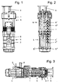
- Fig. 1
- eine Ansicht der Vakuumpumpe;
- Fig. 2
- eine Schnittdarstellung durch die Vakuumpumpe in
Fig. 1 ; - Fig. 3
- eine Längsschnittdarstellung der Vakuumpumpe in
Fig. 1 . - Die Vakuumpumpe weist ein Gehäuse 1 auf. Dieses Gehäuse 1 weist am einen Ende einen Lufteintritt 2 und am anderen Ende einen Luftaustritt 3 auf.
- Im Bereich des Lufteintritts 2 ist in dem Gehäuse 1 eine Drehkolbenpumpe 4 mit zwei Drehkolben 4', 4" auf zugehörigen Wellen 5', 5" vorgesehen. Zwischen den beiden Wellen 5', 5" befindet sich ein Getriebe 7.
- In Strömungsrichtung dahinter schließt sich an die Drehkolbenpumpe 4 eine Schraubenpumpe 6 mit Schrauben 6', 6" an. Diese Schrauben 6', 6" sind dabei auf der gleichen Welle 5', 5" wie die Drehkolbenpumpe 4 angeordnet. In dem dargestellten Ausführungsbeispiel sind dabei die beiden Wellen 5', 5" jedoch nicht durchgehend, sondern zweigeteilt, jedoch koaxial und drehfest miteinander verbunden.
- In
Fig. 2 ist darüber hinaus erkennbar, daß die Schraubenpumpe 6 auf der Eingangsseite eine größere Steigung pro Umdrehung besitzt als auf der Ausgangsseite. Dabei kann sich die Steigung entweder kontinuierlich zur Ausgangsseite hin verringern, oder aber im Bereich der Eingangsseite und/oder im Bereich der Ausgangsseite ist die Steigung jeweils konstant. Es sind dabei in den Bereichen Eingangsseite/Ausgangsseite sämtliche möglichen Kombinationen konstante Steigung / sich verändernde Steigung denkbar. Es muß nur gewährleistet sein, daß sich über die gesamte Pumpstrecke die Steigung verringert. Auf jeden Fall erfolgt in dem Bereich mit der geringeren Steigung eine höhere Verdichtung. Dies erhöht den Wirkungsgrad der Pumpe. - Schließlich ist noch zwischen der Drehkolbenpumpe 4 und der Schraubenpumpe 6 ein Bypassventil 8 angeordnet.
- Die Funktionsweise ist wie folgt:
- Der Antrieb der Vakuumpumpe erfolgt mittels eines - nicht dargestellten - Elektromotors. Dieser ist an einen Anschlußflansch 9 des Gehäuses 1 angeschlossen. Der Elektromotor treibt dabei die Welle 5' an. Über das Getriebe 7 wird dann synchron die zweite Welle 5" angetrieben.
- Die Drehkolbenpumpe 4, welche sich durch ein hohes Saugvermögen auszeichnet, saugt über den Lufteintritt 2 die Luft an und führt diese der Schraubenpumpe 6 zu, welche sich durch ein hohes Kompressionsvermögen auszeichnet. Die Luft tritt dann über den Luftaustritt 3 aus dem Gehäuse 1 aus. Der gesamte Strömungsverlauf ist in den
Fig. 2 und 3 durch die Pfeile angedeutet. - Da die Drehkolbenpumpe 4 ein hohes Saugvermögen besitzt, liefert diese eine sehr hohe Luftmenge an die dahinter befindliche Schraubenpumpe 6. Diese kann aufgrund des geringeren Saugvermögens nicht diese großen Luftmassen nicht immer bewältigen. Wird somit der Druck zu hoch, wird das Bypassventil 8 geöffnet, welches sich zwischen der Drehkolbenpumpe 4 und der Schraubenpumpe 6 befindet, so daß die Luft wieder zu der Drehkolbenpumpe 4 rückgeführt wird.
-
- 1
- Gehäuse
- 2
- Lufteintritt
- 3
- Luftaustritt
- 4
- Drehkolbenpumpe
- 4'
- Drehkolben
- 4"
- Drehkolben
- 5'
- Welle
- 5"
- Welle
- 6
- Schraubenpumpe
- 6'
- Schraube
- 6"
- Schraube
- 7
- Getriebe
- 8
- Bypassventil
- 9
- Anschlußflansch
Claims (5)
- Vakuumpumpe,
bei der in Strömungsrichtung der Luft gesehen zunächst eine Drehkolbenpumpe (4) und anschließend eine Schraubenpumpe (6) vorgesehen ist,
dadurch gekennzeichnet,
daß in einem für beide Pumpen (4, 6) gemeinsamen Gehäuse (1) zwei zueinander parallele Wellen (5', 5") vorgesehen sind,
wobei auf der ersten Welle (5') der erste Drehkolben (4') der Drehkolbenpumpe (4) und die erste Schraube (6') der Schraubenpumpe (6) angeordnet sind und
wobei auf der zweiten Welle (5") der zweite Drehkolben (4") der Drehkolbenpumpe (4) und die zweite Schraube (6") der Schraubenpumpe (6) angeordnet sind. - Vakuumpumpe nach dem vorhergehenden Anspruch,
dadurch gekennzeichnet,
daß die erste Welle (5') mittels eines Elektromotors antreibbar ist und
daß die zweite Welle (5") über ein Getriebe (7) von der ersten Welle (5') antreibbar ist. - Vakuumpumpe nach einem der vorhergehenden Ansprüche,
dadurch gekennzeichnet,
daß zwischen der Drehkolbenpumpe (4) und der Schraubenpumpe (6) ein Überdruckventil vorgesehen ist. - Vakuumpumpe nach Anspruch 3,
dadurch gekennzeichnet,
daß das Überdruckventil ein Bypassventil (8) ist, welches die nicht der Schraubenpumpe (6) zugeführte Luft der Drehkolbenpumpe (4) zurückführt. - Vakuumpumpe nach einem der vorhergehenden Ansprüche,
dadurch gekennzeichnet,
daß die Schraubenpumpe (6) auf der Eingangsseite eine größere Steigung pro Umdrehung besitzt als auf der Ausgangsseite.
Applications Claiming Priority (1)
| Application Number | Priority Date | Filing Date | Title |
|---|---|---|---|
| DE201010014884 DE102010014884A1 (de) | 2010-04-14 | 2010-04-14 | Vakuumpumpe |
Publications (2)
| Publication Number | Publication Date |
|---|---|
| EP2378063A2 true EP2378063A2 (de) | 2011-10-19 |
| EP2378063A3 EP2378063A3 (de) | 2013-05-01 |
Family
ID=44546305
Family Applications (1)
| Application Number | Title | Priority Date | Filing Date |
|---|---|---|---|
| EP11002484.1A Withdrawn EP2378063A3 (de) | 2010-04-14 | 2011-03-25 | Vakuumpumpe |
Country Status (2)
| Country | Link |
|---|---|
| EP (1) | EP2378063A3 (de) |
| DE (1) | DE102010014884A1 (de) |
Family Cites Families (6)
| Publication number | Priority date | Publication date | Assignee | Title |
|---|---|---|---|---|
| EP0965756B1 (de) * | 1998-06-17 | 2006-02-08 | The BOC Group plc | Schraubenpumpe |
| GB0004404D0 (en) * | 2000-02-24 | 2000-04-12 | Boc Group Plc | Improvements in vacuum pumps |
| DE60138636D1 (de) * | 2000-10-18 | 2009-06-18 | Leybold Vakuum Gmbh | Mehrstufiger schraubenrotor |
| JP4218756B2 (ja) * | 2003-10-17 | 2009-02-04 | 株式会社荏原製作所 | 真空排気装置 |
| DE602005006694D1 (de) * | 2004-10-01 | 2008-06-26 | Lot Vacuum Co Ltd | Mehrstufige trockenverdichtende Vakuumpumpe mit einem Roots-rotor und einem Schraubenrotor |
| TWI438342B (zh) * | 2006-07-28 | 2014-05-21 | Lot Vacuum Co Ltd | 具有魯式與螺旋轉子之複合型乾式真空幫浦 |
-
2010
- 2010-04-14 DE DE201010014884 patent/DE102010014884A1/de not_active Withdrawn
-
2011
- 2011-03-25 EP EP11002484.1A patent/EP2378063A3/de not_active Withdrawn
Non-Patent Citations (1)
| Title |
|---|
| None |
Also Published As
| Publication number | Publication date |
|---|---|
| EP2378063A3 (de) | 2013-05-01 |
| DE102010014884A1 (de) | 2011-10-20 |
Similar Documents
| Publication | Publication Date | Title |
|---|---|---|
| EP2914812B1 (de) | Drehkolbenpumpe mit direktantrieb | |
| DE3147824C2 (de) | Mehrstufige Drehkolben-Vakuumpumpe | |
| DE10015139A1 (de) | Motorpumpenaggregat | |
| EP1443210B1 (de) | Motorpumpenaggregat | |
| DE102014002396A1 (de) | Zweispindelige Schraubenspindelpumpe in einflutiger Bauweise | |
| DE3202993C2 (de) | Drehkolbenverdichter | |
| EP3467314B1 (de) | Schraubenpumpe | |
| DE102012112618B3 (de) | Mehrfachpumpe | |
| DE3324583A1 (de) | Zweimaschinen-aggregat mit anschluss fuer einen weiteren verbraucher mechanischer energie | |
| DE102011084828B4 (de) | Förderaggregat | |
| DE202011104491U1 (de) | Wälzkolbenpumpe | |
| DE2918475C2 (de) | Hydraulikanlage für ein Kraftfahrzeug | |
| DE102011003177A1 (de) | Antrieb für einen Spindel-Kompressor | |
| DE102010020690A1 (de) | Hydraulisches Antriebssystem | |
| DE102010028584A1 (de) | Exzenterlager | |
| DE20305937U1 (de) | Pumpe mit integriertem Hydraulik-Motor | |
| EP2378063A2 (de) | Vakuumpumpe | |
| DE102008061805A1 (de) | Vakuumpumpe sowie Pumpelement | |
| DE1528958A1 (de) | Hydraulische Pumpe | |
| DE102014017072A1 (de) | Vorrichtung zum Fördern eines Mediums | |
| DE102021209030A1 (de) | Pumpe mit Pulsationskompensation | |
| DE102022206319A1 (de) | Elektrische Zahnradpumpe für ein Kraftfahrzeug, insbesondere Gerotor-Pumpe sowie Set aus mehreren Zahnradpumpen | |
| WO2018189041A1 (de) | Schraubenverdichteranordnung with synchronsiation gears and transmission gearing | |
| EP3728850B1 (de) | Fluidfördereinrichtung | |
| DE102015005343A1 (de) | Pumpenanordnung für ein Kraftfahrzeug |
Legal Events
| Date | Code | Title | Description |
|---|---|---|---|
| AK | Designated contracting states |
Kind code of ref document: A2 Designated state(s): AL AT BE BG CH CY CZ DE DK EE ES FI FR GB GR HR HU IE IS IT LI LT LU LV MC MK MT NL NO PL PT RO RS SE SI SK SM TR |
|
| AX | Request for extension of the european patent |
Extension state: BA ME |
|
| PUAI | Public reference made under article 153(3) epc to a published international application that has entered the european phase |
Free format text: ORIGINAL CODE: 0009012 |
|
| PUAL | Search report despatched |
Free format text: ORIGINAL CODE: 0009013 |
|
| AK | Designated contracting states |
Kind code of ref document: A3 Designated state(s): AL AT BE BG CH CY CZ DE DK EE ES FI FR GB GR HR HU IE IS IT LI LT LU LV MC MK MT NL NO PL PT RO RS SE SI SK SM TR |
|
| AX | Request for extension of the european patent |
Extension state: BA ME |
|
| RIC1 | Information provided on ipc code assigned before grant |
Ipc: F04C 18/16 20060101ALI20130327BHEP Ipc: F01C 17/00 20060101AFI20130327BHEP Ipc: F04C 23/00 20060101ALI20130327BHEP Ipc: F04C 28/24 20060101ALI20130327BHEP Ipc: F04C 25/02 20060101ALI20130327BHEP Ipc: F04C 18/12 20060101ALI20130327BHEP Ipc: F04C 28/26 20060101ALI20130327BHEP Ipc: F04C 29/00 20060101ALI20130327BHEP |
|
| 17P | Request for examination filed |
Effective date: 20131018 |
|
| RBV | Designated contracting states (corrected) |
Designated state(s): AL AT BE BG CH CY CZ DE DK EE ES FI FR GB GR HR HU IE IS IT LI LT LU LV MC MK MT NL NO PL PT RO RS SE SI SK SM TR |
|
| STAA | Information on the status of an ep patent application or granted ep patent |
Free format text: STATUS: THE APPLICATION IS DEEMED TO BE WITHDRAWN |
|
| 18D | Application deemed to be withdrawn |
Effective date: 20161001 |