EP2378067A2 - Belastungsbeschränkungssystem für ein Rotorunwuchtgewicht und zugehöriges Verfahren - Google Patents
Belastungsbeschränkungssystem für ein Rotorunwuchtgewicht und zugehöriges Verfahren Download PDFInfo
- Publication number
- EP2378067A2 EP2378067A2 EP11159683A EP11159683A EP2378067A2 EP 2378067 A2 EP2378067 A2 EP 2378067A2 EP 11159683 A EP11159683 A EP 11159683A EP 11159683 A EP11159683 A EP 11159683A EP 2378067 A2 EP2378067 A2 EP 2378067A2
- Authority
- EP
- European Patent Office
- Prior art keywords
- hydraulic fluid
- volume hydraulic
- variable volume
- receptacles
- receptacle
- Prior art date
- Legal status (The legal status is an assumption and is not a legal conclusion. Google has not performed a legal analysis and makes no representation as to the accuracy of the status listed.)
- Granted
Links
- 239000012530 fluid Substances 0.000 claims abstract description 223
- 238000000034 method Methods 0.000 claims abstract description 12
- 239000000446 fuel Substances 0.000 description 6
- 238000002485 combustion reaction Methods 0.000 description 4
- 239000000203 mixture Substances 0.000 description 4
- 238000006073 displacement reaction Methods 0.000 description 3
- 238000010586 diagram Methods 0.000 description 2
- 230000000712 assembly Effects 0.000 description 1
- 238000000429 assembly Methods 0.000 description 1
- 230000005484 gravity Effects 0.000 description 1
- 238000000638 solvent extraction Methods 0.000 description 1
Images

Classifications
-
- F—MECHANICAL ENGINEERING; LIGHTING; HEATING; WEAPONS; BLASTING
- F01—MACHINES OR ENGINES IN GENERAL; ENGINE PLANTS IN GENERAL; STEAM ENGINES
- F01D—NON-POSITIVE DISPLACEMENT MACHINES OR ENGINES, e.g. STEAM TURBINES
- F01D5/00—Blades; Blade-carrying members; Heating, heat-insulating, cooling or antivibration means on the blades or the members
- F01D5/02—Blade-carrying members, e.g. rotors
- F01D5/027—Arrangements for balancing
-
- F—MECHANICAL ENGINEERING; LIGHTING; HEATING; WEAPONS; BLASTING
- F16—ENGINEERING ELEMENTS AND UNITS; GENERAL MEASURES FOR PRODUCING AND MAINTAINING EFFECTIVE FUNCTIONING OF MACHINES OR INSTALLATIONS; THERMAL INSULATION IN GENERAL
- F16F—SPRINGS; SHOCK-ABSORBERS; MEANS FOR DAMPING VIBRATION
- F16F15/00—Suppression of vibrations in systems; Means or arrangements for avoiding or reducing out-of-balance forces, e.g. due to motion
- F16F15/32—Correcting- or balancing-weights or equivalent means for balancing rotating bodies, e.g. vehicle wheels
- F16F15/36—Correcting- or balancing-weights or equivalent means for balancing rotating bodies, e.g. vehicle wheels operating automatically, i.e. where, for a given amount of imbalance, there is movement of masses until balance is achieved
- F16F15/366—Correcting- or balancing-weights or equivalent means for balancing rotating bodies, e.g. vehicle wheels operating automatically, i.e. where, for a given amount of imbalance, there is movement of masses until balance is achieved using fluid or powder means, i.e. non-discrete material
-
- F—MECHANICAL ENGINEERING; LIGHTING; HEATING; WEAPONS; BLASTING
- F05—INDEXING SCHEMES RELATING TO ENGINES OR PUMPS IN VARIOUS SUBCLASSES OF CLASSES F01-F04
- F05D—INDEXING SCHEME FOR ASPECTS RELATING TO NON-POSITIVE-DISPLACEMENT MACHINES OR ENGINES, GAS-TURBINES OR JET-PROPULSION PLANTS
- F05D2260/00—Function
- F05D2260/40—Transmission of power
- F05D2260/406—Transmission of power through hydraulic systems
-
- F—MECHANICAL ENGINEERING; LIGHTING; HEATING; WEAPONS; BLASTING
- F05—INDEXING SCHEMES RELATING TO ENGINES OR PUMPS IN VARIOUS SUBCLASSES OF CLASSES F01-F04
- F05D—INDEXING SCHEME FOR ASPECTS RELATING TO NON-POSITIVE-DISPLACEMENT MACHINES OR ENGINES, GAS-TURBINES OR JET-PROPULSION PLANTS
- F05D2270/00—Control
- F05D2270/50—Control logic embodiments
- F05D2270/56—Control logic embodiments by hydraulic means, e.g. hydraulic valves within a hydraulic circuit
-
- F—MECHANICAL ENGINEERING; LIGHTING; HEATING; WEAPONS; BLASTING
- F05—INDEXING SCHEMES RELATING TO ENGINES OR PUMPS IN VARIOUS SUBCLASSES OF CLASSES F01-F04
- F05D—INDEXING SCHEME FOR ASPECTS RELATING TO NON-POSITIVE-DISPLACEMENT MACHINES OR ENGINES, GAS-TURBINES OR JET-PROPULSION PLANTS
- F05D2270/00—Control
- F05D2270/60—Control system actuates means
- F05D2270/64—Hydraulic actuators
-
- F—MECHANICAL ENGINEERING; LIGHTING; HEATING; WEAPONS; BLASTING
- F16—ENGINEERING ELEMENTS AND UNITS; GENERAL MEASURES FOR PRODUCING AND MAINTAINING EFFECTIVE FUNCTIONING OF MACHINES OR INSTALLATIONS; THERMAL INSULATION IN GENERAL
- F16C—SHAFTS; FLEXIBLE SHAFTS; ELEMENTS OR CRANKSHAFT MECHANISMS; ROTARY BODIES OTHER THAN GEARING ELEMENTS; BEARINGS
- F16C19/00—Bearings with rolling contact, for exclusively rotary movement
- F16C19/02—Bearings with rolling contact, for exclusively rotary movement with bearing balls essentially of the same size in one or more circular rows
- F16C19/04—Bearings with rolling contact, for exclusively rotary movement with bearing balls essentially of the same size in one or more circular rows for radial load mainly
- F16C19/06—Bearings with rolling contact, for exclusively rotary movement with bearing balls essentially of the same size in one or more circular rows for radial load mainly with a single row or balls
-
- F—MECHANICAL ENGINEERING; LIGHTING; HEATING; WEAPONS; BLASTING
- F16—ENGINEERING ELEMENTS AND UNITS; GENERAL MEASURES FOR PRODUCING AND MAINTAINING EFFECTIVE FUNCTIONING OF MACHINES OR INSTALLATIONS; THERMAL INSULATION IN GENERAL
- F16C—SHAFTS; FLEXIBLE SHAFTS; ELEMENTS OR CRANKSHAFT MECHANISMS; ROTARY BODIES OTHER THAN GEARING ELEMENTS; BEARINGS
- F16C2360/00—Engines or pumps
- F16C2360/23—Gas turbine engines
-
- F—MECHANICAL ENGINEERING; LIGHTING; HEATING; WEAPONS; BLASTING
- F16—ENGINEERING ELEMENTS AND UNITS; GENERAL MEASURES FOR PRODUCING AND MAINTAINING EFFECTIVE FUNCTIONING OF MACHINES OR INSTALLATIONS; THERMAL INSULATION IN GENERAL
- F16C—SHAFTS; FLEXIBLE SHAFTS; ELEMENTS OR CRANKSHAFT MECHANISMS; ROTARY BODIES OTHER THAN GEARING ELEMENTS; BEARINGS
- F16C27/00—Elastic or yielding bearings or bearing supports, for exclusively rotary movement
- F16C27/04—Ball or roller bearings, e.g. with resilient rolling bodies
- F16C27/045—Ball or roller bearings, e.g. with resilient rolling bodies with a fluid film, e.g. squeeze film damping
Definitions
- the present invention generally relates to rotor support structures, and more particularly relates to a system and method for limiting the load on rotor support structures following an event that causes a rotor imbalance.
- the rotor support structures for some rotating machines are structurally sized to withstand the loads that may occur following a postulated rotor imbalance event.
- the rotor support structure for many aircraft gas turbine engines is sized to withstand a postulated blade loss event.
- Such an event would result in relatively high imbalance loads. Designing the engine to withstand such an event can result in an undesirably heavy engine, which in turn can result in undesirable fuel burn.
- rotor support structures are designed to withstand the loads associated with a postulated rotor imbalance event in a number of ways.
- the rotor support structure may be designed with sufficient structural capacity to withstand worst case rotor imbalance loads.
- This solution can result in an undesirably heavy machine.
- machine weight can be controlled by limiting the imbalance load that may be supplied to the support structure. This can be accomplished through the use of a frangible support section that fails at a predetermined load, or the use of a buckling section that collapses at a predetermined load.
- Another solution is to control the load that may be supplied to the support structure through the use of limited stiffness within the load path to the support structure. With this latter solution the imbalanced rotor is allowed to orbit about a point near its center of gravity while maintaining acceptable load in the support structure.
- a rotor imbalance load limiting system includes a plurality of circumferentially spaced variable volume hydraulic fluid receptacles, a substantially fixed volume hydraulic fluid receptacle, a plurality of flow passages, a plurality of circumferentially spaced pistons, a plurality of first check valves, and a plurality of second check valves.
- Each variable volume hydraulic fluid receptacle has hydraulic fluid disposed therein.
- the substantially fixed volume hydraulic fluid receptacle surrounds the plurality of variable volume hydraulic fluid receptacles and has hydraulic fluid disposed therein.
- the plurality of flow passages interconnects the fixed volume hydraulic fluid receptacle with each of the variable volume hydraulic fluid receptacles.
- Each piston at least engages one of the variable volume hydraulic fluid receptacles and is adapted for at least engaging an outer race of a bearing assembly.
- Each of the first check valves is disposed at least partially within one of the flow passages and is configured to selectively allow hydraulic fluid to flow from one of the variable volume hydraulic fluid receptacles into the fixed volume hydraulic fluid receptacle.
- Each of the second check valves is disposed at least partially within one of the flow passages and is configured to selectively allow hydraulic fluid to flow from the fixed volume hydraulic fluid receptacle into one of the variable volume hydraulic fluid receptacles.
- a machine in another embodiment, includes a rotor, a bearing assembly, and a rotor imbalance load limiting system.
- the bearing assembly rotationally mounts the rotor and includes an inner race and an outer race.
- the inner race at least engages the rotor.
- the rotor imbalance load limiting system at least engages the outer race of the bearing assembly and includes a plurality of circumferentially spaced variable volume hydraulic fluid receptacles, a substantially fixed volume hydraulic fluid receptacle, a plurality of flow passages, a plurality of circumferentially spaced pistons, a plurality of first check valves, and a plurality of second check valves.
- Each variable volume hydraulic fluid receptacle has hydraulic fluid disposed therein.
- the substantially fixed volume hydraulic fluid receptacle surrounds the plurality of variable volume hydraulic fluid receptacles and has hydraulic fluid disposed therein.
- the plurality of flow passages interconnects the fixed volume hydraulic fluid receptacle with each of the variable volume hydraulic fluid receptacles.
- Each piston at least engages one of the variable volume hydraulic fluid receptacles and at least engages the outer race of the bearing assembly.
- Each of the first check valves is disposed at least partially within one of the flow passages and is configured to selectively allow hydraulic fluid to flow from one of the variable volume hydraulic fluid receptacles into the fixed volume hydraulic fluid receptacle.
- Each of the second check valves is disposed at least partially within one of the flow passages and is configured to selectively allow hydraulic fluid to flow from the fixed volume hydraulic fluid receptacle into one of the variable volume hydraulic fluid receptacles.
- a method of limiting load on a rotor support structure when a rotationally mounted rotor becomes imbalanced includes rotationally mounting the rotor within a plurality of circumferentially spaced variable volume hydraulic fluid receptacles that at least engage the rotor and have hydraulic fluid disposed therein.
- Each of the variable volume hydraulic fluid receptacles is fluidly connected to a substantially fixed volume hydraulic fluid receptacle that has hydraulic fluid disposed therein and is coupled to the rotor support structure.
- the hydraulic fluid is continuously moved between the variable volume hydraulic fluid receptacles and the substantially fixed volume hydraulic fluid receptacle.
- FIG. 1 depicts a functional block diagram of an embodiment of a turbofan gas turbine engine
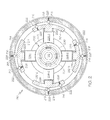
- FIGS. 2 depicts a cross section end view of an embodiment of a portion of a rotor imbalance load limiting system that may be implemented in the turbofan gas turbine engine of FIG. 1 ;
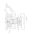
- FIG. 3 depicts a cross section side view of a portion of the rotor imbalance load limiting system depicted in FIG. 2 ;
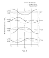
- FIG. 4 graphically depicts fluid movement within the rotor imbalance load limiting system of FIG. 2 .
- the depicted engine 100 is a multi-spool turbofan gas turbine propulsion engine, and includes an intake section 102, a compressor section 104, a combustion section 106, a turbine section 108, and an exhaust section 112.
- the intake section 102 includes an intake fan 114, which is mounted in a nacelle assembly 116.
- the intake fan 114 draws air into the intake section 102 and accelerates it.
- a fraction of the accelerated air exhausted from the intake fan 114 is directed through a bypass flow passage 118 defined between the nacelle assembly 116 and an engine cowl 122. This fraction of air flow is referred to herein as bypass air flow.
- the remaining fraction of air exhausted from the intake fan 114 is directed into the compressor section 104.
- the compressor section 104 may include one or more compressors 124, which raise the pressure of the air directed into it from the intake fan 114, and direct the compressed air into the combustion section 106. In the depicted embodiment, only a single compressor 124 is shown, though it will be appreciated that one or more additional compressors could be used.
- the combustion section 106 which includes a combustor assembly 126, the compressed air is mixed with fuel supplied from a non-illustrated fuel source. The fuel and air mixture is combusted, and the high energy combusted fuel/air mixture is then directed into the turbine section 108.
- the turbine section 108 includes one or more turbines.
- the turbine section 108 includes two turbines, a high pressure turbine 128, and a low pressure turbine 132.
- the engine 100 could be configured with more or less than this number of turbines.
- the combusted fuel/air mixture from the combustion section 106 expands through each turbine 128, 132, causing it to rotate.
- the turbines 128 and 132 rotate, each drives equipment in the engine 100 via concentrically disposed rotors or spools.
- the high pressure turbine 128 drives the compressor 124 via a high pressure rotor 134
- the low pressure turbine 132 drives the intake fan 114 via a low pressure rotor 136.
- the gas exhausted from the turbine section 108 is then directed into the exhaust section 112.
- the exhaust section 112 includes a mixer 138 and an exhaust nozzle 142.
- the mixer 138 includes a centerbody 144 and a mixer nozzle 146, and is configured to mix the bypass air flow with the exhaust gas from the turbine section 108.
- the bypass air/exhaust gas mixture is then expanded through the propulsion nozzle 142, providing forward thrust.
- the intake fan 114 is disposed within a fan case and supported by support structure that is coupled to the nacelle assembly 116.
- the support structure comprises a rotor imbalance load limiting system.
- a cross section end view and a partial cross section side view of an embodiment of a rotor imbalance load limiting system and support structure are depicted in more detail in FIGS. 2 and 3 , and with reference thereto will now be described.
- the low pressure rotor 136 is rotationally mounted in the fan case (see FIG. 3 ) via one or more bearing assemblies 202 (only one depicted).
- the configuration of the bearing assembly 202 may vary, in the depicted embodiment it includes an inner race 204, an outer race 206, and a plurality of bearing balls 208.
- the inner race 202 at least engages the low pressure rotor 136 and rotates therewith, and the outer race 206 is non-rotationally mounted.
- the bearing balls 208 are disposed, in appropriate grooves, within and between the inner race 204 and the outer race 206. Although four bearing balls 208 are depicted in FIG. 2 , it will be appreciated that this is done merely for clarity and ease of illustration and that more than this number may be, and likely are, included.
- the rotor imbalance load limiting system 210 is preferably coupled to, or at least engages, the outer race 206 of the bearing assembly 202 and the fan case 302.
- the rotor imbalance load limiting system 210 includes a plurality of variable volume hydraulic fluid receptacles 212, a fixed volume hydraulic fluid receptacle 214, a plurality of flow passages 216, a plurality of first check valves 218, a plurality of second check valves 222, and a plurality of circumferentially spaced pistons 224.
- the variable volume hydraulic fluid receptacles 212 each have a hydraulic fluid disposed therein and, as the name connotes, the fluid volume of each is variable.
- each variable volume hydraulic fluid receptacle 212 includes a bellows 226, or other similarly functional structure.
- variable volume hydraulic fluid receptacles 212 are evenly spaced circumferentially about the low pressure rotor 136, and thus about the axis of rotation of the low pressure rotor 136.
- the system 210 includes four variable volume hydraulic fluid receptacles 212 (e.g., 212-1, 212-2, 212-3, and 212-4). It will be appreciated, however, that the system 210 could be implemented with more or less than this number of variable volume hydraulic fluid receptacles 212, though the number is preferably an even number.
- the circumferential extent of each variable volume hydraulic fluid receptacle 212 may vary from what is depicted in FIG. 2 .
- each of the variable volume hydraulic fluid receptacles 212 could circumferentially extend to butt up against one another, or even share common partitioning walls.
- the fixed volume hydraulic fluid receptacle 214 also has a hydraulic fluid disposed therein. As its name connotes, the fluid volume of the fixed volume hydraulic fluid receptacle 214 is fixed (or at least substantially fixed).
- the fixed volume hydraulic fluid receptacle 214 extends circumferentially around the variable volume hydraulic fluid receptacles 212. It will be appreciated, however, that this is merely an example of a particular preferred dispositional configuration, and that the fixed volume hydraulic fluid receptacle 214 could be alternatively disposed.
- the fixed volume hydraulic fluid volume 214 is interconnected with each of the variable volume hydraulic fluid receptacles 212 via the plurality of flow passages 216.
- each variable volume hydraulic fluid receptacle 212 is interconnected with the fixed volume hydraulic fluid receptacle 214 via two flow passages 216. It will be appreciated, however, that this is merely exemplary of a particular embodiment, and that other numbers of flow passages 216 could interconnect the fixed volume hydraulic fluid receptacle 214 with each of the variable volume hydraulic fluid receptacles 212.
- the specific locations of the flow passages 216 may vary from what is depicted in FIG. 2 .
- the first check valves 218 and the second check valves 222 are disposed at least partially within the flow passages 216, and thus prevent the hydraulic fluid from freely moving between the variable volume hydraulic fluid receptacles 212 and the fixed volume hydraulic fluid receptacle 214.
- each of the first check valves 218 is disposed at least partially within one of the flow passages 216 and is configured to selectively allow hydraulic fluid to flow from one of the variable volume hydraulic fluid receptacles 212 into the fixed volume hydraulic fluid receptacle 214.
- the second check valves 222 are also each disposed at least partially within one of the flow passages 216.
- the second check valves 222 are each configured to selectively allow hydraulic fluid to flow from the fixed volume hydraulic fluid receptacle 214 into one of the variable volume hydraulic fluid receptacles 212.
- the first check valves 218 and the second check valves 222 are each biased to a closed position, which is the position depicted in FIGS. 2 and 3 . In the closed positions, hydraulic fluid cannot move between the fixed volume hydraulic fluid receptacle 214 and the variable volume hydraulic fluid receptacles 212. In the depicted embodiment, the first check valves 218 and the second check valves 222 are biased to their respective closed positions via springs 228, though this is merely exemplary of a particular embodiment.
- the first check valves 218 are configured to move from the closed position to an open position, and thus allow hydraulic fluid to flow from its associated variable volume hydraulic fluid receptacle 212 into the fixed volume hydraulic fluid receptacle 214, when hydraulic fluid pressure in its associated variable volume hydraulic fluid receptacle 212 exceeds the hydraulic fluid pressure in the fixed volume hydraulic fluid receptacle 214 by a predetermined value.
- each of the second check valves 222 is configured to move from the closed position to an open position, and thus allow hydraulic fluid to flow from the fixed volume hydraulic fluid receptacle 214 into its associated variable volume hydraulic fluid receptacle 212, when the hydraulic fluid pressure in the fixed volume hydraulic fluid receptacle 214 exceeds the hydraulic fluid pressure in the associated variable volume hydraulic fluid receptacle 212 by a predetermined value.
- the predetermined values of hydraulic pressure at which each of the first check valves 218 and the second check valves 222 move from the closed to open positions may vary, and are set, at least in part, by the bias spring force.
- each piston 224 is preferably coupled to, or at least engages, one of the variable volume hydraulic fluid receptacles 212 and the outer race of the bearing assembly 202. More specifically, each piston 224 is preferably coupled to the bellows 226 of one of the variable volume hydraulic fluid receptacles 212.
- the pistons 224 are preferably evenly spaced circumferentially about the low pressure rotor 136, and there is preferably the same number of pistons 224 as variable volume hydraulic fluid receptacles 212.
- pistons 224 e.g., 224-1, 224-2, 224-3, and 224-4
- the pistons 224 locate the outer race 206 of the bearing assembly 202 within the overall system 210 and, as will now be described, selectively compress the bellows 226, and thus vary the fluid volumes of the variable volume hydraulic fluid receptacles 212 should the low pressure rotor 136 become unbalanced.
- the rotor imbalance load limiting system 210 is in the quiescent state depicted in FIG. 2 .
- the first check valves 218 and the second check valves 222 are closed, and there is no hydraulic fluid movement between the variable volume hydraulic fluid receptacles 212 and the fixed volume hydraulic fluid receptacle 214.
- the low pressure rotor 136 for some reason, becomes unbalanced and is initially displaced, when viewed in the context of FIG. 2 , in the upward (e.g., 12 o'clock) direction.
- the fluid volume of the fixed volume hydraulic fluid receptacle 214 is fixed.
- the flow of hydraulic fluid into the fixed volume hydraulic fluid receptacle 214 will cause the hydraulic fluid pressure therein to increase.
- the low pressure rotor 136 is, at least at this instant in time, not displaced in the leftward (9 o'clock) or rightward (3 o'clock) directions, the volumes of the variable volume hydraulic fluid receptacles 212-2, 212-4 at those locations have not changed.
- the associated second check valves 222 remain in their closed positions.
- the volume of the variable volume hydraulic fluid receptacle 212-3 at the 6 o'clock location has increased, causing the hydraulic fluid therein to decrease.
- the system 210 settles into a state in which the hydraulic fluid is continuously moving between the variable volume hydraulic fluid receptacles 212 and the fixed volume hydraulic fluid receptacle 214.
- hydraulic fluid in the variable volume hydraulic fluid receptacles 212 at the maximum rotor displacement and 90-degrees ahead of the maximum rotor displacement is moving into the fixed volume hydraulic fluid cavity 214.
- the hydraulic fluid that is moved into in the fixed volume hydraulic fluid cavity is in turn moving into the variable volume hydraulic fluid receptacles 212 that are 180-degrees and 270-degrees ahead of the maximum rotor displacement.
- This movement of hydraulic fluid in the system 210 is depicted graphically in FIG. 4 . It is noted that in FIG. 4 the solid lines represent the position (outward or inward of normal) of the pistons, while the dashed lines represent the direction of travel (outward or inward) and velocity of the piston.
- variable volume hydraulic fluid receptacles 212 at the 9 o'clock and 6 o'clock positions are supplying hydraulic fluid to the fixed volume hydraulic fluid receptacle 214, and the variable volume hydraulic fluid receptacles 212 at the 3 o'clock and 12 o'clock positions are receiving hydraulic fluid from the fixed volume hydraulic fluid receptacle 214.
- variable volume hydraulic fluid receptacles 212 at the 6 o'clock and 3 o'clock positions are supplying hydraulic fluid to the fixed volume hydraulic fluid receptacle 214, and the variable volume hydraulic fluid receptacles 212 at the 12 o'clock and 9 o'clock positions are receiving hydraulic fluid from the fixed volume hydraulic fluid receptacle 214.
- variable volume hydraulic fluid receptacles 212 at the 3 o'clock and 12 o'clock positions are supplying hydraulic fluid to the fixed volume hydraulic fluid receptacle 214, and the variable volume hydraulic fluid receptacles 212 at the 9 o'clock and 6 o'clock positions are receiving hydraulic fluid from the fixed volume hydraulic fluid receptacle 214.
- variable volume hydraulic fluid receptacles 212 at the 12 o'clock and 9 o'clock positions are supplying hydraulic fluid to the fixed volume hydraulic fluid receptacle 214, and the variable volume hydraulic fluid receptacles 212 at the 6 o'clock and 3 o'clock positions are receiving hydraulic fluid from the fixed volume hydraulic fluid receptacle 214.
- the system and method described herein limit rotor imbalance loads supplied to rotor support structures without undesirably increasing machine weight, without relying on sacrificial components, and not controlling rotor centerline position following a rotor imbalance event.
- rotor imbalance load limiting system and method are conveniently described herein as being implemented in a turbofan gas turbine engine, it will be appreciated that embodiments of the system and method may be implemented in any one of numerous other machines that have rotationally mounted rotors.
Landscapes
- Engineering & Computer Science (AREA)
- General Engineering & Computer Science (AREA)
- Mechanical Engineering (AREA)
- Physics & Mathematics (AREA)
- Acoustics & Sound (AREA)
- Aviation & Aerospace Engineering (AREA)
- Wind Motors (AREA)
- Turbine Rotor Nozzle Sealing (AREA)
- Centrifugal Separators (AREA)
Applications Claiming Priority (1)
| Application Number | Priority Date | Filing Date | Title |
|---|---|---|---|
| US12/758,569 US8491265B2 (en) | 2010-04-12 | 2010-04-12 | Rotor imbalance load limiting system and method |
Publications (3)
| Publication Number | Publication Date |
|---|---|
| EP2378067A2 true EP2378067A2 (de) | 2011-10-19 |
| EP2378067A3 EP2378067A3 (de) | 2017-11-15 |
| EP2378067B1 EP2378067B1 (de) | 2018-11-21 |
Family
ID=43920932
Family Applications (1)
| Application Number | Title | Priority Date | Filing Date |
|---|---|---|---|
| EP11159683.9A Not-in-force EP2378067B1 (de) | 2010-04-12 | 2011-03-24 | System zur Beschränkung einer Belastung aufgrund einer Rotorunwucht |
Country Status (2)
| Country | Link |
|---|---|
| US (1) | US8491265B2 (de) |
| EP (1) | EP2378067B1 (de) |
Cited By (2)
| Publication number | Priority date | Publication date | Assignee | Title |
|---|---|---|---|---|
| WO2015022072A1 (de) * | 2013-08-16 | 2015-02-19 | Brose Fahrzeugteile GmbH & Co. Kommanditgesellschaft, Würzburg | Drehbar gelagerter rotationskörper |
| US10519774B2 (en) | 2015-05-07 | 2019-12-31 | MTU Aero Engines AG | Rotor arrangement for a turbomachine and compressor |
Families Citing this family (3)
| Publication number | Priority date | Publication date | Assignee | Title |
|---|---|---|---|---|
| US8491265B2 (en) * | 2010-04-12 | 2013-07-23 | Honeywell International Inc. | Rotor imbalance load limiting system and method |
| DE102016200906A1 (de) * | 2016-01-22 | 2017-07-27 | Zf Friedrichshafen Ag | Drehschwingungsdämpfungsanordnung für einen Antriebsstrang eines Fahrzeugs |
| CN108644113B (zh) * | 2016-12-21 | 2019-11-05 | 东营市东营区东泊泵业有限公司 | 一种调速运转的增压输送用双螺杆泵 |
Family Cites Families (20)
| Publication number | Priority date | Publication date | Assignee | Title |
|---|---|---|---|---|
| US2659243A (en) | 1951-07-05 | 1953-11-17 | Bbc Brown Boveri & Cie | Apparatus for automatic balancing of rotating bodies |
| US2778243A (en) | 1952-06-26 | 1957-01-22 | Bbc Brown Boveri & Cie | Device for automatic balancing of rotating machine parts |
| DE1026578B (de) * | 1955-02-09 | 1958-03-20 | Licentia Gmbh | Vorrichtung zum selbsttaetigen Auswuchten einer mit ueberkritischer Drehzahl rotierenden Welle |
| NL275196A (de) | 1961-02-28 | |||
| FR1320198A (fr) | 1962-01-26 | 1963-03-08 | S E E P F | Dispositif destiné à assurer la compensation du balourd d'une pièce rotative |
| US3248967A (en) | 1964-01-06 | 1966-05-03 | Exxon Research Engineering Co | Variable inertia liquid flywheel |
| US3812724A (en) | 1969-09-19 | 1974-05-28 | M Matson | Rotational balancer |
| NL7015670A (de) * | 1970-10-07 | 1972-04-11 | ||
| US4002086A (en) * | 1972-06-06 | 1977-01-11 | Rolf Bertil Reinhall | Device for automatic correction of unbalance in rapidly rotating machine elements |
| IT1005170B (it) * | 1972-11-01 | 1976-08-20 | Kagi B | Dispositivo d azionamento per ottenere un movimento oscillatorio o rotatorio per azione di un fluido liquido o gassoso sotto pressione |
| US4295387A (en) | 1979-07-12 | 1981-10-20 | Zhivotov Jury G | Apparatus for balancing bodies of revolution |
| US4990062A (en) * | 1988-11-14 | 1991-02-05 | Impact Mst Incorporated | Positive displacement pumps |
| US5197010A (en) | 1990-12-13 | 1993-03-23 | The Boeing Company | Apparatus for continuously actively balancing rotors |
| US5490436A (en) | 1994-03-17 | 1996-02-13 | At&T Corp. | Liquid-chamber apparatus for active, dynamic balancing of rotating machinery |
| US5860865A (en) | 1996-04-19 | 1999-01-19 | Lockheed Martin Corporation | Pneumatically driven auto-balance rotor hub |
| US6030185A (en) * | 1996-07-11 | 2000-02-29 | Itt Manufacturing Enterprises Inc. | Radial piston pump |
| US5970820A (en) | 1998-04-17 | 1999-10-26 | Lockheed Martin Corp. | Series linkage auto-balance rotor hub |
| US7300260B1 (en) * | 2003-10-31 | 2007-11-27 | Sauer-Danfoss Inc. | Special fluids for use in a hydrostatic transmission |
| US7517152B1 (en) * | 2006-09-20 | 2009-04-14 | Florida Turbine Technologies, Inc. | Squeeze film damper with variable support stiffness |
| US8491265B2 (en) * | 2010-04-12 | 2013-07-23 | Honeywell International Inc. | Rotor imbalance load limiting system and method |
-
2010
- 2010-04-12 US US12/758,569 patent/US8491265B2/en active Active
-
2011
- 2011-03-24 EP EP11159683.9A patent/EP2378067B1/de not_active Not-in-force
Non-Patent Citations (1)
| Title |
|---|
| None |
Cited By (2)
| Publication number | Priority date | Publication date | Assignee | Title |
|---|---|---|---|---|
| WO2015022072A1 (de) * | 2013-08-16 | 2015-02-19 | Brose Fahrzeugteile GmbH & Co. Kommanditgesellschaft, Würzburg | Drehbar gelagerter rotationskörper |
| US10519774B2 (en) | 2015-05-07 | 2019-12-31 | MTU Aero Engines AG | Rotor arrangement for a turbomachine and compressor |
Also Published As
| Publication number | Publication date |
|---|---|
| EP2378067A3 (de) | 2017-11-15 |
| US20110250052A1 (en) | 2011-10-13 |
| EP2378067B1 (de) | 2018-11-21 |
| US8491265B2 (en) | 2013-07-23 |
Similar Documents
| Publication | Publication Date | Title |
|---|---|---|
| JP5956290B2 (ja) | 広帯域減衰システムを含むガスタービンエンジンおよびそれを製造する方法 | |
| EP2378067B1 (de) | System zur Beschränkung einer Belastung aufgrund einer Rotorunwucht | |
| EP3040567B1 (de) | Lageranordnung mit zwei wälzlagern und druckkammern zum vorspannen der wälzlager und zum gleichmässigen verteilen der axiallast auf beide lager | |
| JP2013047515A (ja) | 環状ベアリング支持ダンパ、これを含むガスタービンエンジン、およびこれらの製造方法 | |
| EP3854997A1 (de) | Verbesserte turbinenpositionierung in einem gasturbinenmotor | |
| EP2935975B1 (de) | Bidirektionales hilfsschmiersystem | |
| EP2861831B1 (de) | Rotoranordnung mit ineinandergreifenden laschen | |
| EP1970536A2 (de) | Schaufelbefestigungshaltevorrichtung | |
| EP3375983B1 (de) | Dichtungspaneel für einen gasturbinenmotor | |
| US10907486B2 (en) | Turbomachine module comprising a rotor supporting pitchable blades | |
| US7717669B2 (en) | Load absorption arrangements for gas turbine engines | |
| EP2519727B1 (de) | Gasturbinemotor und lagersystem für hochgeschwindigkeitsrollenelement | |
| WO2015042553A1 (en) | Gas turbine engine aft bearing arrangement | |
| US11702993B2 (en) | Structural assembly for a gas turbine engine | |
| EP2957792B1 (de) | Rotor mit reduzierter schwingungsreaktion für eine gasbetriebene turbine | |
| CN118669235A (zh) | 具有用于可变桨距风扇的叶片桨距致动系统的涡轮发动机 | |
| EP3670942A1 (de) | Lageranordnung mit aktiver schwingungsregelung | |
| EP3032070B2 (de) | Traglastverteilsystem | |
| JP2019044762A (ja) | 単一壁片持ち構造を有するタービンエンジン | |
| EP3800366B1 (de) | Lagerfeder für die gehäuseanordnung eines planetengetriebesystems | |
| US12516668B2 (en) | Gear pump assembly | |
| EP2993330B1 (de) | Entkoppelter gasturbinenmotor | |
| EP3839229A1 (de) | Gasturbinenmotor mit verbesserter resonanzreaktion | |
| WO2020078724A1 (en) | Oil system of a gas turbine engine and gas turbine engine |
Legal Events
| Date | Code | Title | Description |
|---|---|---|---|
| 17P | Request for examination filed |
Effective date: 20110324 |
|
| AK | Designated contracting states |
Kind code of ref document: A2 Designated state(s): AL AT BE BG CH CY CZ DE DK EE ES FI FR GB GR HR HU IE IS IT LI LT LU LV MC MK MT NL NO PL PT RO RS SE SI SK SM TR |
|
| AX | Request for extension of the european patent |
Extension state: BA ME |
|
| PUAI | Public reference made under article 153(3) epc to a published international application that has entered the european phase |
Free format text: ORIGINAL CODE: 0009012 |
|
| RAP1 | Party data changed (applicant data changed or rights of an application transferred) |
Owner name: HONEYWELL INTERNATIONAL INC. |
|
| PUAL | Search report despatched |
Free format text: ORIGINAL CODE: 0009013 |
|
| STAA | Information on the status of an ep patent application or granted ep patent |
Free format text: STATUS: EXAMINATION IS IN PROGRESS |
|
| AK | Designated contracting states |
Kind code of ref document: A3 Designated state(s): AL AT BE BG CH CY CZ DE DK EE ES FI FR GB GR HR HU IE IS IT LI LT LU LV MC MK MT NL NO PL PT RO RS SE SI SK SM TR |
|
| AX | Request for extension of the european patent |
Extension state: BA ME |
|
| RIC1 | Information provided on ipc code assigned before grant |
Ipc: F01D 5/02 20060101AFI20171011BHEP Ipc: F16F 15/36 20060101ALI20171011BHEP |
|
| 17Q | First examination report despatched |
Effective date: 20171110 |
|
| GRAP | Despatch of communication of intention to grant a patent |
Free format text: ORIGINAL CODE: EPIDOSNIGR1 |
|
| STAA | Information on the status of an ep patent application or granted ep patent |
Free format text: STATUS: GRANT OF PATENT IS INTENDED |
|
| INTG | Intention to grant announced |
Effective date: 20180531 |
|
| GRAJ | Information related to disapproval of communication of intention to grant by the applicant or resumption of examination proceedings by the epo deleted |
Free format text: ORIGINAL CODE: EPIDOSDIGR1 |
|
| GRAL | Information related to payment of fee for publishing/printing deleted |
Free format text: ORIGINAL CODE: EPIDOSDIGR3 |
|
| GRAS | Grant fee paid |
Free format text: ORIGINAL CODE: EPIDOSNIGR3 |
|
| STAA | Information on the status of an ep patent application or granted ep patent |
Free format text: STATUS: EXAMINATION IS IN PROGRESS |
|
| GRAP | Despatch of communication of intention to grant a patent |
Free format text: ORIGINAL CODE: EPIDOSNIGR1 |
|
| STAA | Information on the status of an ep patent application or granted ep patent |
Free format text: STATUS: GRANT OF PATENT IS INTENDED |
|
| GRAA | (expected) grant |
Free format text: ORIGINAL CODE: 0009210 |
|
| STAA | Information on the status of an ep patent application or granted ep patent |
Free format text: STATUS: THE PATENT HAS BEEN GRANTED |
|
| INTC | Intention to grant announced (deleted) | ||
| RIC1 | Information provided on ipc code assigned before grant |
Ipc: F16C 27/04 20060101ALN20180920BHEP Ipc: F16F 15/36 20060101ALI20180920BHEP Ipc: F16C 19/06 20060101ALN20180920BHEP Ipc: F01D 5/02 20060101AFI20180920BHEP |
|
| INTG | Intention to grant announced |
Effective date: 20181009 |
|
| AK | Designated contracting states |
Kind code of ref document: B1 Designated state(s): AL AT BE BG CH CY CZ DE DK EE ES FI FR GB GR HR HU IE IS IT LI LT LU LV MC MK MT NL NO PL PT RO RS SE SI SK SM TR |
|
| REG | Reference to a national code |
Ref country code: CH Ref legal event code: EP |
|
| REG | Reference to a national code |
Ref country code: IE Ref legal event code: FG4D |
|
| REG | Reference to a national code |
Ref country code: DE Ref legal event code: R096 Ref document number: 602011054013 Country of ref document: DE |
|
| REG | Reference to a national code |
Ref country code: AT Ref legal event code: REF Ref document number: 1067782 Country of ref document: AT Kind code of ref document: T Effective date: 20181215 |
|
| REG | Reference to a national code |
Ref country code: NL Ref legal event code: MP Effective date: 20181121 |
|
| REG | Reference to a national code |
Ref country code: AT Ref legal event code: MK05 Ref document number: 1067782 Country of ref document: AT Kind code of ref document: T Effective date: 20181121 |
|
| PG25 | Lapsed in a contracting state [announced via postgrant information from national office to epo] |
Ref country code: IS Free format text: LAPSE BECAUSE OF FAILURE TO SUBMIT A TRANSLATION OF THE DESCRIPTION OR TO PAY THE FEE WITHIN THE PRESCRIBED TIME-LIMIT Effective date: 20190321 Ref country code: FI Free format text: LAPSE BECAUSE OF FAILURE TO SUBMIT A TRANSLATION OF THE DESCRIPTION OR TO PAY THE FEE WITHIN THE PRESCRIBED TIME-LIMIT Effective date: 20181121 Ref country code: NO Free format text: LAPSE BECAUSE OF FAILURE TO SUBMIT A TRANSLATION OF THE DESCRIPTION OR TO PAY THE FEE WITHIN THE PRESCRIBED TIME-LIMIT Effective date: 20190221 Ref country code: LV Free format text: LAPSE BECAUSE OF FAILURE TO SUBMIT A TRANSLATION OF THE DESCRIPTION OR TO PAY THE FEE WITHIN THE PRESCRIBED TIME-LIMIT Effective date: 20181121 Ref country code: AT Free format text: LAPSE BECAUSE OF FAILURE TO SUBMIT A TRANSLATION OF THE DESCRIPTION OR TO PAY THE FEE WITHIN THE PRESCRIBED TIME-LIMIT Effective date: 20181121 Ref country code: ES Free format text: LAPSE BECAUSE OF FAILURE TO SUBMIT A TRANSLATION OF THE DESCRIPTION OR TO PAY THE FEE WITHIN THE PRESCRIBED TIME-LIMIT Effective date: 20181121 Ref country code: LT Free format text: LAPSE BECAUSE OF FAILURE TO SUBMIT A TRANSLATION OF THE DESCRIPTION OR TO PAY THE FEE WITHIN THE PRESCRIBED TIME-LIMIT Effective date: 20181121 Ref country code: BG Free format text: LAPSE BECAUSE OF FAILURE TO SUBMIT A TRANSLATION OF THE DESCRIPTION OR TO PAY THE FEE WITHIN THE PRESCRIBED TIME-LIMIT Effective date: 20190221 Ref country code: HR Free format text: LAPSE BECAUSE OF FAILURE TO SUBMIT A TRANSLATION OF THE DESCRIPTION OR TO PAY THE FEE WITHIN THE PRESCRIBED TIME-LIMIT Effective date: 20181121 |
|
| PG25 | Lapsed in a contracting state [announced via postgrant information from national office to epo] |
Ref country code: PT Free format text: LAPSE BECAUSE OF FAILURE TO SUBMIT A TRANSLATION OF THE DESCRIPTION OR TO PAY THE FEE WITHIN THE PRESCRIBED TIME-LIMIT Effective date: 20190321 Ref country code: AL Free format text: LAPSE BECAUSE OF FAILURE TO SUBMIT A TRANSLATION OF THE DESCRIPTION OR TO PAY THE FEE WITHIN THE PRESCRIBED TIME-LIMIT Effective date: 20181121 Ref country code: SE Free format text: LAPSE BECAUSE OF FAILURE TO SUBMIT A TRANSLATION OF THE DESCRIPTION OR TO PAY THE FEE WITHIN THE PRESCRIBED TIME-LIMIT Effective date: 20181121 Ref country code: GR Free format text: LAPSE BECAUSE OF FAILURE TO SUBMIT A TRANSLATION OF THE DESCRIPTION OR TO PAY THE FEE WITHIN THE PRESCRIBED TIME-LIMIT Effective date: 20190222 Ref country code: RS Free format text: LAPSE BECAUSE OF FAILURE TO SUBMIT A TRANSLATION OF THE DESCRIPTION OR TO PAY THE FEE WITHIN THE PRESCRIBED TIME-LIMIT Effective date: 20181121 Ref country code: NL Free format text: LAPSE BECAUSE OF FAILURE TO SUBMIT A TRANSLATION OF THE DESCRIPTION OR TO PAY THE FEE WITHIN THE PRESCRIBED TIME-LIMIT Effective date: 20181121 |
|
| PG25 | Lapsed in a contracting state [announced via postgrant information from national office to epo] |
Ref country code: CZ Free format text: LAPSE BECAUSE OF FAILURE TO SUBMIT A TRANSLATION OF THE DESCRIPTION OR TO PAY THE FEE WITHIN THE PRESCRIBED TIME-LIMIT Effective date: 20181121 Ref country code: IT Free format text: LAPSE BECAUSE OF FAILURE TO SUBMIT A TRANSLATION OF THE DESCRIPTION OR TO PAY THE FEE WITHIN THE PRESCRIBED TIME-LIMIT Effective date: 20181121 Ref country code: PL Free format text: LAPSE BECAUSE OF FAILURE TO SUBMIT A TRANSLATION OF THE DESCRIPTION OR TO PAY THE FEE WITHIN THE PRESCRIBED TIME-LIMIT Effective date: 20181121 Ref country code: DK Free format text: LAPSE BECAUSE OF FAILURE TO SUBMIT A TRANSLATION OF THE DESCRIPTION OR TO PAY THE FEE WITHIN THE PRESCRIBED TIME-LIMIT Effective date: 20181121 |
|
| REG | Reference to a national code |
Ref country code: DE Ref legal event code: R097 Ref document number: 602011054013 Country of ref document: DE |
|
| PG25 | Lapsed in a contracting state [announced via postgrant information from national office to epo] |
Ref country code: EE Free format text: LAPSE BECAUSE OF FAILURE TO SUBMIT A TRANSLATION OF THE DESCRIPTION OR TO PAY THE FEE WITHIN THE PRESCRIBED TIME-LIMIT Effective date: 20181121 Ref country code: SM Free format text: LAPSE BECAUSE OF FAILURE TO SUBMIT A TRANSLATION OF THE DESCRIPTION OR TO PAY THE FEE WITHIN THE PRESCRIBED TIME-LIMIT Effective date: 20181121 Ref country code: RO Free format text: LAPSE BECAUSE OF FAILURE TO SUBMIT A TRANSLATION OF THE DESCRIPTION OR TO PAY THE FEE WITHIN THE PRESCRIBED TIME-LIMIT Effective date: 20181121 Ref country code: SK Free format text: LAPSE BECAUSE OF FAILURE TO SUBMIT A TRANSLATION OF THE DESCRIPTION OR TO PAY THE FEE WITHIN THE PRESCRIBED TIME-LIMIT Effective date: 20181121 |
|
| PLBE | No opposition filed within time limit |
Free format text: ORIGINAL CODE: 0009261 |
|
| STAA | Information on the status of an ep patent application or granted ep patent |
Free format text: STATUS: NO OPPOSITION FILED WITHIN TIME LIMIT |
|
| 26N | No opposition filed |
Effective date: 20190822 |
|
| PG25 | Lapsed in a contracting state [announced via postgrant information from national office to epo] |
Ref country code: MC Free format text: LAPSE BECAUSE OF FAILURE TO SUBMIT A TRANSLATION OF THE DESCRIPTION OR TO PAY THE FEE WITHIN THE PRESCRIBED TIME-LIMIT Effective date: 20181121 Ref country code: SI Free format text: LAPSE BECAUSE OF FAILURE TO SUBMIT A TRANSLATION OF THE DESCRIPTION OR TO PAY THE FEE WITHIN THE PRESCRIBED TIME-LIMIT Effective date: 20181121 |
|
| REG | Reference to a national code |
Ref country code: CH Ref legal event code: PL |
|
| GBPC | Gb: european patent ceased through non-payment of renewal fee |
Effective date: 20190324 |
|
| PG25 | Lapsed in a contracting state [announced via postgrant information from national office to epo] |
Ref country code: LU Free format text: LAPSE BECAUSE OF NON-PAYMENT OF DUE FEES Effective date: 20190324 |
|
| REG | Reference to a national code |
Ref country code: BE Ref legal event code: MM Effective date: 20190331 |
|
| PG25 | Lapsed in a contracting state [announced via postgrant information from national office to epo] |
Ref country code: LI Free format text: LAPSE BECAUSE OF NON-PAYMENT OF DUE FEES Effective date: 20190331 Ref country code: CH Free format text: LAPSE BECAUSE OF NON-PAYMENT OF DUE FEES Effective date: 20190331 Ref country code: IE Free format text: LAPSE BECAUSE OF NON-PAYMENT OF DUE FEES Effective date: 20190324 Ref country code: GB Free format text: LAPSE BECAUSE OF NON-PAYMENT OF DUE FEES Effective date: 20190324 |
|
| PG25 | Lapsed in a contracting state [announced via postgrant information from national office to epo] |
Ref country code: BE Free format text: LAPSE BECAUSE OF NON-PAYMENT OF DUE FEES Effective date: 20190331 Ref country code: FR Free format text: LAPSE BECAUSE OF NON-PAYMENT OF DUE FEES Effective date: 20190331 |
|
| PG25 | Lapsed in a contracting state [announced via postgrant information from national office to epo] |
Ref country code: TR Free format text: LAPSE BECAUSE OF FAILURE TO SUBMIT A TRANSLATION OF THE DESCRIPTION OR TO PAY THE FEE WITHIN THE PRESCRIBED TIME-LIMIT Effective date: 20181121 |
|
| PG25 | Lapsed in a contracting state [announced via postgrant information from national office to epo] |
Ref country code: MT Free format text: LAPSE BECAUSE OF NON-PAYMENT OF DUE FEES Effective date: 20190324 |
|
| PG25 | Lapsed in a contracting state [announced via postgrant information from national office to epo] |
Ref country code: CY Free format text: LAPSE BECAUSE OF FAILURE TO SUBMIT A TRANSLATION OF THE DESCRIPTION OR TO PAY THE FEE WITHIN THE PRESCRIBED TIME-LIMIT Effective date: 20181121 |
|
| PG25 | Lapsed in a contracting state [announced via postgrant information from national office to epo] |
Ref country code: HU Free format text: LAPSE BECAUSE OF FAILURE TO SUBMIT A TRANSLATION OF THE DESCRIPTION OR TO PAY THE FEE WITHIN THE PRESCRIBED TIME-LIMIT; INVALID AB INITIO Effective date: 20110324 |
|
| PGFP | Annual fee paid to national office [announced via postgrant information from national office to epo] |
Ref country code: DE Payment date: 20220329 Year of fee payment: 12 |
|
| PG25 | Lapsed in a contracting state [announced via postgrant information from national office to epo] |
Ref country code: MK Free format text: LAPSE BECAUSE OF FAILURE TO SUBMIT A TRANSLATION OF THE DESCRIPTION OR TO PAY THE FEE WITHIN THE PRESCRIBED TIME-LIMIT Effective date: 20181121 |
|
| P01 | Opt-out of the competence of the unified patent court (upc) registered |
Effective date: 20230525 |
|
| REG | Reference to a national code |
Ref country code: DE Ref legal event code: R119 Ref document number: 602011054013 Country of ref document: DE |
|
| PG25 | Lapsed in a contracting state [announced via postgrant information from national office to epo] |
Ref country code: DE Free format text: LAPSE BECAUSE OF NON-PAYMENT OF DUE FEES Effective date: 20231003 |