EP2378075A1 - Laufschaufel und zugehöriges Gasturbinenkraftwerk - Google Patents
Laufschaufel und zugehöriges Gasturbinenkraftwerk Download PDFInfo
- Publication number
- EP2378075A1 EP2378075A1 EP11159161A EP11159161A EP2378075A1 EP 2378075 A1 EP2378075 A1 EP 2378075A1 EP 11159161 A EP11159161 A EP 11159161A EP 11159161 A EP11159161 A EP 11159161A EP 2378075 A1 EP2378075 A1 EP 2378075A1
- Authority
- EP
- European Patent Office
- Prior art keywords
- mean camber
- gutter
- tip
- centre line
- line
- Prior art date
- Legal status (The legal status is an assumption and is not a legal conclusion. Google has not performed a legal analysis and makes no representation as to the accuracy of the status listed.)
- Withdrawn
Links
- 239000000567 combustion gas Substances 0.000 description 12
- 239000007789 gas Substances 0.000 description 9
- 230000001141 propulsive effect Effects 0.000 description 3
- 238000005452 bending Methods 0.000 description 1
- 230000015572 biosynthetic process Effects 0.000 description 1
- 238000002485 combustion reaction Methods 0.000 description 1
- 230000006835 compression Effects 0.000 description 1
- 238000007906 compression Methods 0.000 description 1
- 230000000694 effects Effects 0.000 description 1
- 239000000446 fuel Substances 0.000 description 1
- 239000000203 mixture Substances 0.000 description 1
- 238000010248 power generation Methods 0.000 description 1
- 238000004904 shortening Methods 0.000 description 1
Images




Classifications
-
- F—MECHANICAL ENGINEERING; LIGHTING; HEATING; WEAPONS; BLASTING
- F01—MACHINES OR ENGINES IN GENERAL; ENGINE PLANTS IN GENERAL; STEAM ENGINES
- F01D—NON-POSITIVE DISPLACEMENT MACHINES OR ENGINES, e.g. STEAM TURBINES
- F01D5/00—Blades; Blade-carrying members; Heating, heat-insulating, cooling or antivibration means on the blades or the members
- F01D5/12—Blades
- F01D5/14—Form or construction
- F01D5/20—Specially-shaped blade tips to seal space between tips and stator
Definitions
- the present invention relates to rotor blades.
- Rotor blades are used in gas turbine engines to interact with combustion gases to convert kinetic energy of the combustion gases into rotation of the rotor.
- the efficiency of the engine is affected by the manner in which the combustion gases flow around the rotor blades.
- Examples of the present invention provide a rotor blade having an aerofoil portion with a leading edge, a trailing edge, a tip and a root, there being at least one gutter extending across the tip to an exit in the region of the trailing edge, the aerofoil portion having a mean camber line and the gutter having a centre line when viewed from the tip towards the root, and the blade being characterised in that the conditions that (a) the mean camber line and centre line coincide at the exit when viewed as aforesaid, and (b) the mean camber line and the centre line are parallel at the exit when viewed as aforesaid, are not both fulfilled.
- Examples of the present invention also provide a gas turbine engine characterised by comprising at least one rotor blade according to this aspect of the invention.
- a gas turbine engine is generally indicated at 10 and comprises, in axial flow series, an air intake 11, a propulsive fan 12, an intermediate pressure compressor 13, a high pressure compressor 14, a combustor 15, a turbine arrangement comprising a high pressure turbine 16, an intermediate pressure turbine 17 and a low pressure turbine 18, and an exhaust nozzle 19.
- the gas turbine engine 10 operates in a conventional manner so that air entering the intake 11 is accelerated by the fan 12 which produce two air flows: a first air flow into the intermediate pressure compressor 13 and a second air flow which provides propulsive thrust.
- the intermediate pressure compressor compresses the air flow directed into it before delivering that air to the high pressure compressor 14 where further compression takes place.
- the compressed air exhausted from the high pressure compressor 14 is directed into the combustor 15 where it is mixed with fuel and the mixture combusted.
- the resultant hot combustion products then expand through, and thereby drive, the high, intermediate and low pressure turbines 16, 17 and 18 before being exhausted through the nozzle 19 to provide additional propulsive thrust.
- the high, intermediate and low pressure turbines 16, 17 and 18 respectively drive the high and intermediate pressure compressors 14 and 13 and the fan 12 by suitable interconnecting shafts 26, 28, 30.
- the efficiency of the engine is affected by the manner in which the combustion gases flow around the rotor blades, as noted above.
- a recognized problem exists arising from leakage of combustion gases between the rotating tip of the turbine blades and the stationary casing which surrounds them. This leakage is sometimes called "over tip leakage".
- Previous proposals for addressing losses arising from over tip leakage have included the provision of a rotating shroud carried by the rotor blade tips and carrying fins which act as labyrinth seals.
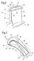
- FIG. 2 illustrates a single rotor blade 40 for use in one of the turbines 16, 17, 18 of the gas turbine engine 10.
- the blade 40 has an aerofoil portion 42 which interacts with combustion gases passing through the turbine.
- the aerofoil portion 42 has a leading edge 44 and a trailing edge 46.
- a root 48 which may be shrouded, provides for mounting the blade 40 on a rotor disc (not shown) in conventional manner.
- the aerofoil portion 42 has a suction face 50 and a pressure face 52.
- the aerodynamic form of the portion 42 creates aerodynamic lift, which in turn creates rotation in the turbine, thus turning the turbine disc.
- the blade 40 has a tip 54 which is at the radially outer end of the blade 40, when the turbine is rotating.
- the tip 54 carries winglets 56, 58 which project laterally from the blade 40, at the radially outer end of the suction face 50 and pressure face 52, respectively.
- the winglets provide an end face 60 to the blade 40.
- a gutter 62 extends across the tip 54. That is, the gutter 62 is provided across the end face 60.
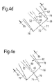
- the gutter 62 extends from a mouth 64 in the region of the leading edge 44, to an exit 66 in the region of the trailing edge 46. That is, when viewed from the tip 54 along the blade 40 toward the root 48, the leading edge 44 is within or close to the mouth 64 and the trailing edge 46 is within or close to the exit 66.
- This view is shown in figure 3 , on which the shapes of the suction face 50 and pressure face 52 are indicated in broken lines, so that the positions of the leading edge 44 and trailing edge 46 relative to the mouth 64 and exit 66 can be seen.
- the lateral overhang of the winglets 56, 58 can also be seen in figure 3 .
- the aerofoil portion 42 has a mean camber line 70 ( Fig. 3 ).
- the mean camber line 70 is the line of points which lie equidistant from the suction face 50 and the pressure face 52, at any position along the aerofoil portion 42, between the leading edge 44 and the trailing edge 46. Accordingly, the mean camber line 70 extends from the leading edge 44 to the trailing edge 46.
- the gutter 62 has a centre line 71 when viewed from the tip 54 towards the root 48.
- the centre line 71 is the line of points which lie halfway across the gutter 62, at any position along the gutter 62. That is, each point lies halfway between the boundaries 76, 78 which define the width of the gutter 62. Accordingly, the centre line 71 extends along the whole length of the gutter 62.
- the mean camber line 70 and the centre line 71 of the gutter 62 may coincide at the exit 66 when viewed from the tip 54 towards the root 48, or the centre line of the gutter 62 may be offset relative to the mean camber line 70 of the aerofoil portion 42.
- the mean camber line 70 of the aerofoil portion 42 and the centre line 71 of the gutter 62 may be parallel at the exit 66 when viewed from the tip 54 towards the root 48, or the centre line 71 of the gutter 62 may be differently directed to the mean camber line 70 of the aerofoil portion 42, so that the two are not parallel.
- Figure 3 shows the mean camber line 70 of the aerofoil portion 42.
- Figure 3 also shows the centre line 71 of the gutter 62.
- the mouth 64 is aligned with the leading edge 44.
- the centre line 71 of the gutter 62, at the mouth 64 is centred at the mean camber line 70. This also places the mouth 64 substantially at the stagnation point 72 of the airflow 74 at the leading edge 44.
- the centre line 71 of the gutter 62 remains substantially aligned with the mean camber line 70, as can be seen in figure 3 . That is, the boundaries 76, 78 of the gutter 62 lie equidistant to each side of the mean camber line 70, along much of the length of the gutter 62.
- Fig. 4a to h various alignments are envisaged, illustrated in Fig. 4a to h.
- Figs. 5a to 5c are sections to assist in understanding the relative positions of the mean camber line 70 and the centre line 71.
- the mean camber line 70 and the centre line 71 do not coincide at the exit when viewed from the tip 54 towards the root 48.
- the centre line 71 of the gutter 62 is offset from the mean camber line 70 of the aerofoil portion, in the direction of the suction face 50 of the aerofoil portion 42. This can be seen most clearly in Fig. 5a .
- condition (a) is not fulfilled.
- the mean camber line 70 and the centre line 71 are not parallel at the exit 66 when viewed from the tip 54 towards the root 48.
- the centre line 71 of the gutter 62 is directed more towards the suction face side of the mean camber line 70.
- condition (b) is not fulfilled.
- the two conditions are not both fulfilled.
- the mean camber line 70 and the centre line 71 do not coincide at the exit when viewed from the tip 54 towards the root 48, as can be seen in Fig. 5b .
- the centre line 71 of the gutter 62 is offset from the centre line 70 of the aerofoil portion, in the direction of the suction face 50.
- condition (a) is not fulfilled.
- the mean camber line 70 and the centre line 71 are parallel at the exit 66 when viewed from the tip 54 towards the root 48.
- condition (b) is fulfilled, but the two conditions are not both fulfilled.
- the mean camber line 70 and the centre line 71 do not coincide at the exit when viewed from the tip 54 towards the root 48, as can be seen in Fig. 5c .
- the centre line 71 of the gutter 62 is offset from the centre line 70 of the aerofoil portion, in the direction of the suction face 50.
- condition (a) is not fulfilled.
- the mean camber line 70 and the centre line 71 are not parallel at the exit 66 when viewed from the tip 54 towards the root 48.
- the centre line 71 of the gutter 62 is directed more towards the pressure face side of the mean camber line 70.
- condition (b) is not fulfilled.
- neither condition is fulfilled.
- the mean camber line 70 and the centre line 71 do not coincide at the exit when viewed from the tip 54 towards the root 48, as can be seen in Fig. 5f.
- the centre line 71 of the gutter 72 is offset from the mean camber line 70, in the direction of the pressure face 52 of the aerofoil portion 42.
- condition (a) is not fulfilled.
- the mean camber line 70 and the centre line 71 are not parallel at the exit 66 when viewed from the tip 54 towards the root 48.
- the centre line 71 of the gutter 62 is directed more towards the suction face side of the mean camber line 70.
- condition (b) is not fulfilled.
- neither of the two conditions is fulfilled.
- the mean camber line 70 and the centre line 71 do not coincide at the exit when viewed from the tip 54 towards the root 48, as can be seen in Fig. 5g.
- the centre line 71 of the gutter 72 is offset from the mean camber line 70, in the direction of the pressure face 52 of the aerofoil portion 42.
- condition (a) is not fulfilled.
- the mean camber line 70 and the centre line 71 are parallel at the exit 66 when viewed from the tip 54 towards the root 48.
- condition (b) is fulfilled.
- the two conditions are not both fulfilled.
- the mean camber line 70 and the centre line 71 do not coincide at the exit when viewed from the tip 54 towards the root 48, as can be seen in Fig. 5h.
- the centre line 71 of the gutter 72 is offset from the mean camber line 70, in the direction of the pressure face 52 of the aerofoil portion 42.
- condition (a) is not fulfilled.
- the mean camber line 70 and the centre line 71 are not parallel at the exit 66 when viewed from the tip 54 towards the root 48.
- the centre line 71 of the gutter 62 is directed more towards the pressure face side of the mean camber line 70.
- condition (b) is not fulfilled.
- neither of the two conditions is fulfilled.
- condition (a) depends on the spacing of the boundaries 76, 78 of the gutter 62, from the mean camber line 70. This may, in turn, be affected by the degree of overhang of each of the winglets 56, 58.
- the applicability of condition (b) depends on the direction of the boundaries 76, 78 at the exit 66, relative to the direction of the mean camber line 70.
- condition (a) relates to the position of the gutter exit 66 relative to the trailing edge 46 and thus affects the position at which combustion gas leaves the exit 66 to return to the main combustion gas flow.
- Condition (b) relates to the direction of the gutter exit 66 relative to the trailing edge 46 and thus affects the angle at which combustion gas returns to the main combustion gas flow. Consequently, choosing the position and direction of the gutter exit 66 provides control over mixing losses associated with the return of gases from the gutter to the main flow.
- Figure 6 illustrates a tip 54a which generally corresponds closely with the tip 54 described above.
- the tip 54a differs from the tip 54 in that there is a cut-away 94 in the region of the exit 66. That is, the winglet 56 is cut back, thus also shortening the boundary 78. This reduces the mass of the winglet 56 and the extent of the overhang of the winglet 56. This is expected to result in reduced bending loads or other reduced stresses in the region of the trailing edge 46.
- the removal of the cut-away 94 will also affect gas flow in the region of the trailing edge 46 and should therefore be designed to avoid reintroducing losses of the type discussed above.
- the formation of the cutaway 94 results in the centre line 71 being closer to the suction face 50 than the mean camber line 70 is, and also in the centre line 71 being directed more towards the suction face 50 than the mean camber line 70 is.
- turbine blades described above can be used in aero engines, marine engines or industrial engines, or for power generation.
Landscapes
- Engineering & Computer Science (AREA)
- Mechanical Engineering (AREA)
- General Engineering & Computer Science (AREA)
- Structures Of Non-Positive Displacement Pumps (AREA)
Applications Claiming Priority (1)
| Application Number | Priority Date | Filing Date | Title |
|---|---|---|---|
| GB201006450A GB201006450D0 (en) | 2010-04-19 | 2010-04-19 | Blades |
Publications (1)
| Publication Number | Publication Date |
|---|---|
| EP2378075A1 true EP2378075A1 (de) | 2011-10-19 |
Family
ID=42245383
Family Applications (1)
| Application Number | Title | Priority Date | Filing Date |
|---|---|---|---|
| EP11159161A Withdrawn EP2378075A1 (de) | 2010-04-19 | 2011-03-22 | Laufschaufel und zugehöriges Gasturbinenkraftwerk |
Country Status (3)
| Country | Link |
|---|---|
| US (1) | US8845280B2 (de) |
| EP (1) | EP2378075A1 (de) |
| GB (1) | GB201006450D0 (de) |
Cited By (2)
| Publication number | Priority date | Publication date | Assignee | Title |
|---|---|---|---|---|
| WO2015197328A1 (en) * | 2014-06-25 | 2015-12-30 | Siemens Aktiengesellschaft | Compressor aerofoil and corresponding compressor rotor assembly |
| CN105909315A (zh) * | 2015-02-25 | 2016-08-31 | 通用电气公司 | 涡轮转子叶片 |
Families Citing this family (7)
| Publication number | Priority date | Publication date | Assignee | Title |
|---|---|---|---|---|
| US10087764B2 (en) * | 2012-03-08 | 2018-10-02 | Pratt & Whitney Canada Corp. | Airfoil for gas turbine engine |
| US9593584B2 (en) * | 2012-10-26 | 2017-03-14 | Rolls-Royce Plc | Turbine rotor blade of a gas turbine |
| EP2987956A1 (de) * | 2014-08-18 | 2016-02-24 | Siemens Aktiengesellschaft | Verdichterschaufel |
| MX392790B (es) | 2015-04-08 | 2025-03-24 | Horton Inc | Caracteristicas de superficie de aspa de ventilador. |
| US10107108B2 (en) | 2015-04-29 | 2018-10-23 | General Electric Company | Rotor blade having a flared tip |
| US10253637B2 (en) | 2015-12-11 | 2019-04-09 | General Electric Company | Method and system for improving turbine blade performance |
| US10801331B2 (en) | 2016-06-07 | 2020-10-13 | Raytheon Technologies Corporation | Gas turbine engine rotor including squealer tip pocket |
Citations (7)
| Publication number | Priority date | Publication date | Assignee | Title |
|---|---|---|---|---|
| DE1937395A1 (de) * | 1969-07-23 | 1971-02-11 | Dettmering Prof Dr Ing Wilhelm | Gitter zur Vermeidung der Sekundaerstroemung |
| SU779591A1 (ru) * | 1978-12-14 | 1980-11-15 | Ленинградский Ордена Ленина Кораблестроительный Институт | Рабочее колесо турбомашины |
| US5733102A (en) * | 1996-12-17 | 1998-03-31 | General Electric Company | Slot cooled blade tip |
| US6059530A (en) * | 1998-12-21 | 2000-05-09 | General Electric Company | Twin rib turbine blade |
| EP1541806A2 (de) * | 2003-12-11 | 2005-06-15 | ROLLS-ROYCE plc | Verbesserte Blattspitzendichtung einer Turbinenrotorschaufel |
| US20050232771A1 (en) * | 2004-04-17 | 2005-10-20 | Harvey Neil W | Turbine rotor blades |
| US20090162200A1 (en) * | 2007-12-19 | 2009-06-25 | Rolls-Royce Plc | Rotor blades |
Family Cites Families (10)
| Publication number | Priority date | Publication date | Assignee | Title |
|---|---|---|---|---|
| US3635585A (en) * | 1969-12-23 | 1972-01-18 | Westinghouse Electric Corp | Gas-cooled turbine blade |
| JP3137527B2 (ja) * | 1994-04-21 | 2001-02-26 | 三菱重工業株式会社 | ガスタービン動翼チップ冷却装置 |
| US5503527A (en) * | 1994-12-19 | 1996-04-02 | General Electric Company | Turbine blade having tip slot |
| GB9607578D0 (en) | 1996-04-12 | 1996-06-12 | Rolls Royce Plc | Turbine rotor blades |
| US7059834B2 (en) * | 2003-01-24 | 2006-06-13 | United Technologies Corporation | Turbine blade |
| US6923623B2 (en) * | 2003-08-07 | 2005-08-02 | General Electric Company | Perimeter-cooled turbine bucket airfoil cooling hole location, style and configuration |
| US7513743B2 (en) * | 2006-05-02 | 2009-04-07 | Siemens Energy, Inc. | Turbine blade with wavy squealer tip rail |
| US7494319B1 (en) * | 2006-08-25 | 2009-02-24 | Florida Turbine Technologies, Inc. | Turbine blade tip configuration |
| US7934906B2 (en) * | 2007-11-14 | 2011-05-03 | Siemens Energy, Inc. | Turbine blade tip cooling system |
| GB0815957D0 (en) | 2008-09-03 | 2008-10-08 | Rolls Royce Plc | Blades |
-
2010
- 2010-04-19 GB GB201006450A patent/GB201006450D0/en not_active Ceased
-
2011
- 2011-03-22 EP EP11159161A patent/EP2378075A1/de not_active Withdrawn
- 2011-03-22 US US13/069,011 patent/US8845280B2/en not_active Expired - Fee Related
Patent Citations (7)
| Publication number | Priority date | Publication date | Assignee | Title |
|---|---|---|---|---|
| DE1937395A1 (de) * | 1969-07-23 | 1971-02-11 | Dettmering Prof Dr Ing Wilhelm | Gitter zur Vermeidung der Sekundaerstroemung |
| SU779591A1 (ru) * | 1978-12-14 | 1980-11-15 | Ленинградский Ордена Ленина Кораблестроительный Институт | Рабочее колесо турбомашины |
| US5733102A (en) * | 1996-12-17 | 1998-03-31 | General Electric Company | Slot cooled blade tip |
| US6059530A (en) * | 1998-12-21 | 2000-05-09 | General Electric Company | Twin rib turbine blade |
| EP1541806A2 (de) * | 2003-12-11 | 2005-06-15 | ROLLS-ROYCE plc | Verbesserte Blattspitzendichtung einer Turbinenrotorschaufel |
| US20050232771A1 (en) * | 2004-04-17 | 2005-10-20 | Harvey Neil W | Turbine rotor blades |
| US20090162200A1 (en) * | 2007-12-19 | 2009-06-25 | Rolls-Royce Plc | Rotor blades |
Cited By (7)
| Publication number | Priority date | Publication date | Assignee | Title |
|---|---|---|---|---|
| WO2015197328A1 (en) * | 2014-06-25 | 2015-12-30 | Siemens Aktiengesellschaft | Compressor aerofoil and corresponding compressor rotor assembly |
| EP2960434A1 (de) | 2014-06-25 | 2015-12-30 | Siemens Aktiengesellschaft | Verdichterprofil und zugehörige Verdichterrotorbaugruppe |
| CN106460527A (zh) * | 2014-06-25 | 2017-02-22 | 西门子股份公司 | 压气机翼型和对应的压气机转子组件 |
| US20170102004A1 (en) * | 2014-06-25 | 2017-04-13 | Siemens Aktiengesellschaft | Compressor aerofoil and corresponding compressor rotor assembly |
| US10267330B2 (en) * | 2014-06-25 | 2019-04-23 | Siemens Aktiengesellschaft | Compressor aerofoil and corresponding compressor rotor assembly |
| CN105909315A (zh) * | 2015-02-25 | 2016-08-31 | 通用电气公司 | 涡轮转子叶片 |
| EP3061914A1 (de) * | 2015-02-25 | 2016-08-31 | General Electric Company | Turbinenlaufschaufel und zugehöriges gasturbinenkraftwerk |
Also Published As
| Publication number | Publication date |
|---|---|
| GB201006450D0 (en) | 2010-06-02 |
| US20110255986A1 (en) | 2011-10-20 |
| US8845280B2 (en) | 2014-09-30 |
Similar Documents
| Publication | Publication Date | Title |
|---|---|---|
| EP2378075A1 (de) | Laufschaufel und zugehöriges Gasturbinenkraftwerk | |
| EP1505302B1 (de) | Kompressorschaufel | |
| EP1939398B1 (de) | Leitschaufel mit lean und sweep | |
| EP2820279B1 (de) | Turbomaschinenschaufel | |
| EP2631491B1 (de) | Transsonische laufschaufel | |
| CN103184898B (zh) | 具有导流凹槽的燃气涡轮喷嘴 | |
| JP6047141B2 (ja) | 高キャンバーステータベーン | |
| CA2613601C (en) | A turbine assembly for a gas turbine engine and method of manufacturing the same | |
| EP2479382B1 (de) | Rotorblatt | |
| US8317465B2 (en) | Systems and apparatus relating to turbine engines and seals for turbine engines | |
| EP3026214B1 (de) | Schaufel mit gestufter spannweitiger dickenverteilung | |
| US12320274B2 (en) | Compressor stator with leading edge fillet | |
| CN103184897B (zh) | 具有导流栅的燃气涡轮喷嘴 | |
| US8851833B2 (en) | Blades | |
| CN107044444B (zh) | 涡轮发动机压缩机叶片 | |
| EP3392459A1 (de) | Verdichterschaufeln | |
| JPH10131706A (ja) | 燃焼タービン用翼形 | |
| US7874794B2 (en) | Blade row for a rotary machine and method of fabricating same | |
| EP2221454A1 (de) | Gasturbinenschaufel mit Deckbandteile | |
| CA2827566C (en) | Airfoil with tip extension for gas turbine engine | |
| WO2017200549A1 (en) | Tip shroud with a fence feature for discouraging pitch-wise over-tip leakage flow |
Legal Events
| Date | Code | Title | Description |
|---|---|---|---|
| AK | Designated contracting states |
Kind code of ref document: A1 Designated state(s): AL AT BE BG CH CY CZ DE DK EE ES FI FR GB GR HR HU IE IS IT LI LT LU LV MC MK MT NL NO PL PT RO RS SE SI SK SM TR |
|
| AX | Request for extension of the european patent |
Extension state: BA ME |
|
| PUAI | Public reference made under article 153(3) epc to a published international application that has entered the european phase |
Free format text: ORIGINAL CODE: 0009012 |
|
| 17P | Request for examination filed |
Effective date: 20120323 |
|
| RAP1 | Party data changed (applicant data changed or rights of an application transferred) |
Owner name: ROLLS-ROYCE PLC |
|
| STAA | Information on the status of an ep patent application or granted ep patent |
Free format text: STATUS: THE APPLICATION IS DEEMED TO BE WITHDRAWN |
|
| 18D | Application deemed to be withdrawn |
Effective date: 20151001 |