EP2378097A1 - Motor - Google Patents
Motor Download PDFInfo
- Publication number
- EP2378097A1 EP2378097A1 EP09838328A EP09838328A EP2378097A1 EP 2378097 A1 EP2378097 A1 EP 2378097A1 EP 09838328 A EP09838328 A EP 09838328A EP 09838328 A EP09838328 A EP 09838328A EP 2378097 A1 EP2378097 A1 EP 2378097A1
- Authority
- EP
- European Patent Office
- Prior art keywords
- ammonia
- engine
- fed
- gaseous ammonia
- gaseous
- Prior art date
- Legal status (The legal status is an assumption and is not a legal conclusion. Google has not performed a legal analysis and makes no representation as to the accuracy of the status listed.)
- Granted
Links
- QGZKDVFQNNGYKY-UHFFFAOYSA-N Ammonia Chemical compound N QGZKDVFQNNGYKY-UHFFFAOYSA-N 0.000 claims abstract description 336
- 229910021529 ammonia Inorganic materials 0.000 claims abstract description 150
- 239000003054 catalyst Substances 0.000 claims abstract description 42
- 238000011144 upstream manufacturing Methods 0.000 claims abstract description 6
- 238000002485 combustion reaction Methods 0.000 claims description 34
- 239000000446 fuel Substances 0.000 claims description 25
- 238000003860 storage Methods 0.000 claims description 13
- 238000001816 cooling Methods 0.000 claims description 5
- 239000007788 liquid Substances 0.000 claims description 4
- 239000007789 gas Substances 0.000 description 71
- 238000010586 diagram Methods 0.000 description 11
- GWEVSGVZZGPLCZ-UHFFFAOYSA-N Titan oxide Chemical compound O=[Ti]=O GWEVSGVZZGPLCZ-UHFFFAOYSA-N 0.000 description 4
- 239000000567 combustion gas Substances 0.000 description 4
- 230000004048 modification Effects 0.000 description 4
- 238000012986 modification Methods 0.000 description 4
- 238000009826 distribution Methods 0.000 description 3
- 239000003502 gasoline Substances 0.000 description 3
- 238000011084 recovery Methods 0.000 description 3
- VNWKTOKETHGBQD-UHFFFAOYSA-N methane Chemical compound C VNWKTOKETHGBQD-UHFFFAOYSA-N 0.000 description 2
- 238000000034 method Methods 0.000 description 2
- 238000010248 power generation Methods 0.000 description 2
- 238000009834 vaporization Methods 0.000 description 2
- 230000008016 vaporization Effects 0.000 description 2
- 239000006200 vaporizer Substances 0.000 description 2
- 238000009835 boiling Methods 0.000 description 1
- 238000005485 electric heating Methods 0.000 description 1
- 238000002474 experimental method Methods 0.000 description 1
- 239000002803 fossil fuel Substances 0.000 description 1
- 238000004519 manufacturing process Methods 0.000 description 1
- 239000003345 natural gas Substances 0.000 description 1
- 238000010792 warming Methods 0.000 description 1
Images




Classifications
-
- F—MECHANICAL ENGINEERING; LIGHTING; HEATING; WEAPONS; BLASTING
- F02—COMBUSTION ENGINES; HOT-GAS OR COMBUSTION-PRODUCT ENGINE PLANTS
- F02M—SUPPLYING COMBUSTION ENGINES IN GENERAL WITH COMBUSTIBLE MIXTURES OR CONSTITUENTS THEREOF
- F02M21/00—Apparatus for supplying engines with non-liquid fuels, e.g. gaseous fuels stored in liquid form
- F02M21/08—Apparatus for supplying engines with non-liquid fuels, e.g. gaseous fuels stored in liquid form for non-gaseous fuels
- F02M21/10—Apparatus for supplying engines with non-liquid fuels, e.g. gaseous fuels stored in liquid form for non-gaseous fuels for fuels with low melting point, e.g. apparatus having heating means
-
- F—MECHANICAL ENGINEERING; LIGHTING; HEATING; WEAPONS; BLASTING
- F02—COMBUSTION ENGINES; HOT-GAS OR COMBUSTION-PRODUCT ENGINE PLANTS
- F02C—GAS-TURBINE PLANTS; AIR INTAKES FOR JET-PROPULSION PLANTS; CONTROLLING FUEL SUPPLY IN AIR-BREATHING JET-PROPULSION PLANTS
- F02C3/00—Gas-turbine plants characterised by the use of combustion products as the working fluid
- F02C3/20—Gas-turbine plants characterised by the use of combustion products as the working fluid using a special fuel, oxidant, or dilution fluid to generate the combustion products
-
- F—MECHANICAL ENGINEERING; LIGHTING; HEATING; WEAPONS; BLASTING
- F02—COMBUSTION ENGINES; HOT-GAS OR COMBUSTION-PRODUCT ENGINE PLANTS
- F02C—GAS-TURBINE PLANTS; AIR INTAKES FOR JET-PROPULSION PLANTS; CONTROLLING FUEL SUPPLY IN AIR-BREATHING JET-PROPULSION PLANTS
- F02C3/00—Gas-turbine plants characterised by the use of combustion products as the working fluid
- F02C3/20—Gas-turbine plants characterised by the use of combustion products as the working fluid using a special fuel, oxidant, or dilution fluid to generate the combustion products
- F02C3/22—Gas-turbine plants characterised by the use of combustion products as the working fluid using a special fuel, oxidant, or dilution fluid to generate the combustion products the fuel or oxidant being gaseous at standard temperature and pressure
-
- F—MECHANICAL ENGINEERING; LIGHTING; HEATING; WEAPONS; BLASTING
- F02—COMBUSTION ENGINES; HOT-GAS OR COMBUSTION-PRODUCT ENGINE PLANTS
- F02C—GAS-TURBINE PLANTS; AIR INTAKES FOR JET-PROPULSION PLANTS; CONTROLLING FUEL SUPPLY IN AIR-BREATHING JET-PROPULSION PLANTS
- F02C3/00—Gas-turbine plants characterised by the use of combustion products as the working fluid
- F02C3/20—Gas-turbine plants characterised by the use of combustion products as the working fluid using a special fuel, oxidant, or dilution fluid to generate the combustion products
- F02C3/26—Gas-turbine plants characterised by the use of combustion products as the working fluid using a special fuel, oxidant, or dilution fluid to generate the combustion products the fuel or oxidant being solid or pulverulent, e.g. in slurry or suspension
- F02C3/28—Gas-turbine plants characterised by the use of combustion products as the working fluid using a special fuel, oxidant, or dilution fluid to generate the combustion products the fuel or oxidant being solid or pulverulent, e.g. in slurry or suspension using a separate gas producer for gasifying the fuel before combustion
-
- F—MECHANICAL ENGINEERING; LIGHTING; HEATING; WEAPONS; BLASTING
- F02—COMBUSTION ENGINES; HOT-GAS OR COMBUSTION-PRODUCT ENGINE PLANTS
- F02C—GAS-TURBINE PLANTS; AIR INTAKES FOR JET-PROPULSION PLANTS; CONTROLLING FUEL SUPPLY IN AIR-BREATHING JET-PROPULSION PLANTS
- F02C7/00—Features, components parts, details or accessories, not provided for in, or of interest apart form groups F02C1/00 - F02C6/00; Air intakes for jet-propulsion plants
- F02C7/22—Fuel supply systems
-
- F—MECHANICAL ENGINEERING; LIGHTING; HEATING; WEAPONS; BLASTING
- F02—COMBUSTION ENGINES; HOT-GAS OR COMBUSTION-PRODUCT ENGINE PLANTS
- F02C—GAS-TURBINE PLANTS; AIR INTAKES FOR JET-PROPULSION PLANTS; CONTROLLING FUEL SUPPLY IN AIR-BREATHING JET-PROPULSION PLANTS
- F02C7/00—Features, components parts, details or accessories, not provided for in, or of interest apart form groups F02C1/00 - F02C6/00; Air intakes for jet-propulsion plants
- F02C7/22—Fuel supply systems
- F02C7/224—Heating fuel before feeding to the burner
-
- F—MECHANICAL ENGINEERING; LIGHTING; HEATING; WEAPONS; BLASTING
- F02—COMBUSTION ENGINES; HOT-GAS OR COMBUSTION-PRODUCT ENGINE PLANTS
- F02D—CONTROLLING COMBUSTION ENGINES
- F02D19/00—Controlling engines characterised by their use of non-liquid fuels, pluralities of fuels, or non-fuel substances added to the combustible mixtures
- F02D19/12—Controlling engines characterised by their use of non-liquid fuels, pluralities of fuels, or non-fuel substances added to the combustible mixtures peculiar to engines working with non-fuel substances or with anti-knock agents, e.g. with anti-knock fuel
-
- F—MECHANICAL ENGINEERING; LIGHTING; HEATING; WEAPONS; BLASTING
- F23—COMBUSTION APPARATUS; COMBUSTION PROCESSES
- F23J—REMOVAL OR TREATMENT OF COMBUSTION PRODUCTS OR COMBUSTION RESIDUES; FLUES
- F23J15/00—Arrangements of devices for treating smoke or fumes
- F23J15/02—Arrangements of devices for treating smoke or fumes of purifiers, e.g. for removing noxious material
-
- F—MECHANICAL ENGINEERING; LIGHTING; HEATING; WEAPONS; BLASTING
- F23—COMBUSTION APPARATUS; COMBUSTION PROCESSES
- F23R—GENERATING COMBUSTION PRODUCTS OF HIGH PRESSURE OR HIGH VELOCITY, e.g. GAS-TURBINE COMBUSTION CHAMBERS
- F23R3/00—Continuous combustion chambers using liquid or gaseous fuel
- F23R3/28—Continuous combustion chambers using liquid or gaseous fuel characterised by the fuel supply
- F23R3/286—Continuous combustion chambers using liquid or gaseous fuel characterised by the fuel supply having fuel-air premixing devices
-
- F—MECHANICAL ENGINEERING; LIGHTING; HEATING; WEAPONS; BLASTING
- F05—INDEXING SCHEMES RELATING TO ENGINES OR PUMPS IN VARIOUS SUBCLASSES OF CLASSES F01-F04
- F05D—INDEXING SCHEME FOR ASPECTS RELATING TO NON-POSITIVE-DISPLACEMENT MACHINES OR ENGINES, GAS-TURBINES OR JET-PROPULSION PLANTS
- F05D2270/00—Control
- F05D2270/01—Purpose of the control system
- F05D2270/08—Purpose of the control system to produce clean exhaust gases
- F05D2270/082—Purpose of the control system to produce clean exhaust gases with as little NOx as possible
-
- F—MECHANICAL ENGINEERING; LIGHTING; HEATING; WEAPONS; BLASTING
- F23—COMBUSTION APPARATUS; COMBUSTION PROCESSES
- F23J—REMOVAL OR TREATMENT OF COMBUSTION PRODUCTS OR COMBUSTION RESIDUES; FLUES
- F23J2219/00—Treatment devices
- F23J2219/10—Catalytic reduction devices
-
- F—MECHANICAL ENGINEERING; LIGHTING; HEATING; WEAPONS; BLASTING
- F23—COMBUSTION APPARATUS; COMBUSTION PROCESSES
- F23L—SUPPLYING AIR OR NON-COMBUSTIBLE LIQUIDS OR GASES TO COMBUSTION APPARATUS IN GENERAL ; VALVES OR DAMPERS SPECIALLY ADAPTED FOR CONTROLLING AIR SUPPLY OR DRAUGHT IN COMBUSTION APPARATUS; INDUCING DRAUGHT IN COMBUSTION APPARATUS; TOPS FOR CHIMNEYS OR VENTILATING SHAFTS; TERMINALS FOR FLUES
- F23L2900/00—Special arrangements for supplying or treating air or oxidant for combustion; Injecting inert gas, water or steam into the combustion chamber
- F23L2900/00001—Treating oxidant before combustion, e.g. by adding a catalyst
-
- F—MECHANICAL ENGINEERING; LIGHTING; HEATING; WEAPONS; BLASTING
- F23—COMBUSTION APPARATUS; COMBUSTION PROCESSES
- F23R—GENERATING COMBUSTION PRODUCTS OF HIGH PRESSURE OR HIGH VELOCITY, e.g. GAS-TURBINE COMBUSTION CHAMBERS
- F23R2900/00—Special features of, or arrangements for continuous combustion chambers; Combustion processes therefor
- F23R2900/00002—Gas turbine combustors adapted for fuels having low heating value [LHV]
-
- Y—GENERAL TAGGING OF NEW TECHNOLOGICAL DEVELOPMENTS; GENERAL TAGGING OF CROSS-SECTIONAL TECHNOLOGIES SPANNING OVER SEVERAL SECTIONS OF THE IPC; TECHNICAL SUBJECTS COVERED BY FORMER USPC CROSS-REFERENCE ART COLLECTIONS [XRACs] AND DIGESTS
- Y02—TECHNOLOGIES OR APPLICATIONS FOR MITIGATION OR ADAPTATION AGAINST CLIMATE CHANGE
- Y02T—CLIMATE CHANGE MITIGATION TECHNOLOGIES RELATED TO TRANSPORTATION
- Y02T10/00—Road transport of goods or passengers
- Y02T10/10—Internal combustion engine [ICE] based vehicles
- Y02T10/12—Improving ICE efficiencies
-
- Y—GENERAL TAGGING OF NEW TECHNOLOGICAL DEVELOPMENTS; GENERAL TAGGING OF CROSS-SECTIONAL TECHNOLOGIES SPANNING OVER SEVERAL SECTIONS OF THE IPC; TECHNICAL SUBJECTS COVERED BY FORMER USPC CROSS-REFERENCE ART COLLECTIONS [XRACs] AND DIGESTS
- Y02—TECHNOLOGIES OR APPLICATIONS FOR MITIGATION OR ADAPTATION AGAINST CLIMATE CHANGE
- Y02T—CLIMATE CHANGE MITIGATION TECHNOLOGIES RELATED TO TRANSPORTATION
- Y02T10/00—Road transport of goods or passengers
- Y02T10/10—Internal combustion engine [ICE] based vehicles
- Y02T10/30—Use of alternative fuels, e.g. biofuels
-
- Y—GENERAL TAGGING OF NEW TECHNOLOGICAL DEVELOPMENTS; GENERAL TAGGING OF CROSS-SECTIONAL TECHNOLOGIES SPANNING OVER SEVERAL SECTIONS OF THE IPC; TECHNICAL SUBJECTS COVERED BY FORMER USPC CROSS-REFERENCE ART COLLECTIONS [XRACs] AND DIGESTS
- Y02—TECHNOLOGIES OR APPLICATIONS FOR MITIGATION OR ADAPTATION AGAINST CLIMATE CHANGE
- Y02T—CLIMATE CHANGE MITIGATION TECHNOLOGIES RELATED TO TRANSPORTATION
- Y02T50/00—Aeronautics or air transport
- Y02T50/60—Efficient propulsion technologies, e.g. for aircraft
Definitions
- the present invention relates to an engine.
- An object of the present invention is to provide an engine using ammonia as fuel so as to achieve combustion without producing CO 2 and, further, using the action of this ammonia in reducing NO x so as to greatly reduce the amount of NO x discharged into the atmosphere.
- an engine fueled by ammonia which arranges in an exhaust passage of the engine an NO x selective reduction catalyst able to selectively reduce NO x contained in exhaust gas in the presence of ammonia, wherein fuel feeding means for feeding fuel comprised of gaseous ammonia in a combustion chamber of the engine is provided, and ammonia is fed to one or both of an inside of an intake passage of the engine or an inside of an exhaust passage upstream of the NO x selective reduction catalyst so as to reduce the NO x contained in the exhaust gas at the NO x selective reduction catalyst by fed ammonia.
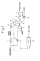
- FIG. 1 is a system diagram of a power plant according to the present invention
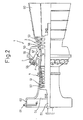
- FIG. 2 is a view illustratively showing one example of a gas turbine engine
- FIG. 3 is a system diagram of another embodiment of a power plant
- FIG. 4 is a system diagram of still another embodiment of a power plant
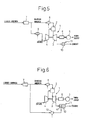
- FIG. 5 is a system diagram of still another embodiment of a power plant
- FIG. 6 is a system diagram of still another embodiment of a power plant
- FIG. 7 is a system diagram of still another embodiment of a power plant
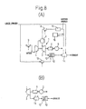
- FIG. 8 is a system diagram of still another embodiment of a power plant and a modification of the same
- FIG. 9 is a system diagram of still another embodiment of a power plant
- FIG. 10 is a system diagram of still another embodiment of a power plant and a modification of the same
- FIG. 11 is a system diagram of still another embodiment of a power plant.
- FIG. 1 is a system diagram of a power plant according to the present invention.
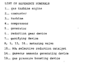
- 1 indicates a gas turbine engine, 2 a combuster of the gas turbine engine, 3 a turbine, 4 a compressor driven by a turbine 3, 5 a generator driven by the gas turbine engine 1 via a reduction gear device 6, 7 a gasifying device of fuel, 8 and 9 fuel metering valves, 10 an NO x selective reduction catalyst arranged in an exhaust passage of the turbine 3, that is, in an exhaust passage of the gas turbine engine 1, and 11 an electronic control unit ECU.
- the NO x selective reduction catalyst 10 is arranged in the exhaust heat recovery device 11.
- the NO x selective reduction catalyst 10 is for example comprised of a honeycomb structure carrying titania TiO 2 .
- This NO x selective reduction catalyst 10 can selectively reduce NO x contained in exhaust gas in the presence of ammonia.
- the electronic control unit 30 receives as input a signal showing the output of the generator 5, a signal showing the speed of the generator 5, a signal showing an outlet temperature of the compressor 4, a signal showing an inlet temperature of the compressor 4, a signal showing an outlet pressure of the compressor 4, a signal showing an inlet temperature of the turbine 3, a signal showing an NO x concentration in the exhaust gas passing through the NO x selective reduction catalyst 10, a signal showing the air temperature, and various other input signals.
- the metering valves 8 and 9 are controlled by output signals of the electronic control unit 30 based on these input signals etc.
- FIG. 2 shows a partial cross-sectional side view illustratively showing an example of the gas turbine engine 1 of FIG. 1 .
- an output shaft 51 is rotatably supported inside a casing 50 of the gas turbine 1, inside a casing 50 of the gas turbine 1, an output shaft 51 is rotatably supported. This output shaft 51 is coupled through the reduction gear device 6 to the generator 5.
- the compressor 4 is comprised of a multistage compressor having a plurality of stationary blades 52 supported by the casing 50 and a plurality of moving blades 53 formed on the output shaft 51. Intake air sucked in from an intake port 54 is compressed by the compressor 4 and fed into a combuster 2.
- a plurality of combusters 2 are arranged around the output shaft 51.
- Each combuster 2 is comprised of a combustion chamber 55, a fuel feed device 56 for feeding fuel into the combustion chamber 55, and a combuster tail pipe 57 extending from the combustion chamber 55 toward the turbine 3.
- Part of the compressed air flowing out from the compressor 4, as shown by the arrow A in FIG. 2 is fed into the combustion chamber 55.
- the fuel fed from the fuel feed device 56 is made to burn in the combustion chamber 55.
- the combustion gas in the combustion chamber 55 is fed through the combuster tail pipe 57 into the turbine 3 where it is used to give the turbine 3 a rotary force.
- part of the compressed air flowing out from the compressor 4 is, as shown in FIG. 2 by the arrow B, fed into the combuster tail pipe 57 so that the inlet temperature of the turbine 3 does not excessively rise.
- the turbine 3 is comprised of a multistage turbine having a plurality of stationary blades 58 supported by the casing 50 and a plurality of moving blades 59 formed on the output shaft 51. The combustion gas flowing out from the turbine 3 forms exhaust gas which is then exhausted from an exhaust port 60.
- ammonia is used as a fuel.
- Gaseous ammonia is fed from the fuel feed device 56 into the combustion chamber 55. This gaseous ammonia is made to burn in the combustion chamber 55.
- the combustion gas of the gaseous ammonia is used to give the turbine 3 a rotary force. When ammonia burns, it forms N 2 and E 2 O-Almost no CO 2 is produced at all. Therefore, this gas turbine engine 1 does not exhaust any CO 2 at all.
- the exhaust gas exhausted from the gas turbine engine 1 contains NO x .
- this NO x is reduced in the NO x selective reduction catalyst 10 arranged inside the exhaust passage of the gas turbine engine 1, ( FIG. 1 ). At this time, for the NO x selective reduction catalyst 10 to reduce the NO x , ammonia is necessary. Below, the method of feeding this ammonia will be explained.
- an ammonia feed device is arranged for feeding liquid ammonia. Liquid ammonia is fed from this ammonia feed device to the inside of the intake passage.
- this ammonia feed devise 61 is arranged inside an intake duct 62. Liquid ammonia is fed from this ammonia feed device 61 to the inside of the intake port 54.
- the boiling point of ammonia is -33.5°C.
- the latent heat of vaporization when liquid ammonia vaporizes is four times that of gasoline and extremely large. Therefore, if liquid ammonia is injected from the ammonia feed device 61 into the intake air, the latent heat of vaporization of the liquid ammonia causes the intake air to be powerfully cooled. Consequently, the inlet temperature of the turbine 3 is made to greatly fall.
- the unburned ammonia fed into the turbine 3 is exhausted into the exhaust passage of the gas turbine engine 1.
- this unburned ammonia is fed into the NO x selective reduction catalyst 10. Therefore, the NO x contained in the exhaust gas is made to be reduced by the unburned ammonia exhausted into the exhaust passage in the NO x selective reduction catalyst 10.
- running liquid ammonia into the intake air flowing into the compressor 4 this ammonia is sufficiently mixed with the intake air in the compressor 4.
- the unburned ammonia is sufficiently mixed in the turbine 3. Therefore, the distribution of concentration of the unburned ammonia in the exhaust gas flowing into the NO x selective reduction catalyst 10 becomes uniform and consequently the action of the NO x selective reduction catalyst 10 in reducing the NO x is made to improve.
- the liquid ammonia fed from the ammonia feed device 61 performs two actions: the action of cooling the intake air and the action of reducing the NO x in the NO x , selective reduction catalyst 10. Further, by feeding liquid ammonia into the intake air flowing into the compressor 4, it is possible to make the distribution of the concentration of the unburned ammonia in the exhaust gas flowing into the NO x selective reduction catalyst 10 uniform and consequently possible to make the action of the NO x selective reduction catalyst 10 in reducing the NO x better.
- liquid ammonia which is stored in a not shown ammonia storage tank is on the one hand fed through the gasifying device 7 and the metering valve 8 to the combuster 2 and on the other hand is fed through the metering valve 9 into the intake flowing into the compressor 4, that is, the intake air.
- the exhaust gas which is exhausted from the turbine 3 is fed into the NO x selective reduction catalyst 10.
- the gasifying device 7 is provided with an evaporator which for example uses electric heating to convert liquid ammonia to gaseous ammonia and a gas compressor for boosting the gaseous ammonia to the feed pressure in the combuster 2. As shown in FIG. 1 , the gaseous ammonia which is fed out from the gasifying device 7 is fed through the metering valve 8 to the combuster 2.
- the liquid ammonia is gasified to make it burn in the combuster 2.
- the same liquid ammonia is used as the liquid ammonia which is used for generating the gaseous ammonia which is fed into the combustion chamber 55 of the combuster 2 and the liquid ammonia which is fed into the intake passage of the gas turbine engine 1, therefore it is possible to streamline the power generation system.
- the amount of fuel which is fed to the combuster 2 that is, the amount of gaseous ammonia
- the amount of liquid ammonia which is fed into the intake passage of the gas turbine engine 1 is controlled by the metering valve 9 so that the amount of unburned ammonia becomes an amount enabling the NO x which is contained in the exhaust gas to be reduced by a predetermined setting or more, for example, by a predetermined reduction rate or more.
- the amount of feed of the liquid ammonia is either set in accordance to the operating state of the gas turbine engine 1 to the optimal feed amount found in advance by experiments or is feedback controlled so that the NO x concentration from the NO x selective reduction catalyst 10 which is detected by an NO x concentration sensor becomes a predetermined range of concentration.
- FIG. 3 shows another embodiment of a power plant.
- an ammonia feed device 12 is arranged for feeding ammonia to the NO x selective reduction catalyst 10.
- the liquid ammonia is sprayed through the metering valve 13 from this ammonia feed device 12 toward the NO x selective reduction catalyst 10.
- the NO x which is contained in the exhaust gas is reduced in the NO x selective reduction catalyst 10 by the liquid ammonia which is fed from the ammonia feed device 12.
- the same liquid ammonia is used as the liquid ammonia which is used for generating the gaseous ammonia which is fed into the combustion chamber 55 of the combuster 2 and the liquid ammonia which is fed from the ammonia feed device 12 to the inside of the exhaust passage. Therefore, it is possible to streamline the power generation system.
- FIG. 4 shows still another embodiment of a power plant.
- the liquid ammonia is on the other hand fed into the intake air and on the other hand is fed from the ammonia feed device 12 to the NO x , selective reduction catalyst 10.
- the insufficient amount of ammonia is fed from the ammonia feed device 12 to the NO x selective reduction catalyst 10.
- FIG. 5 shows still another embodiment of a power plant.
- gaseous ammonia which is fed out from the gasifying device 7 is fed through the metering valve 9 to the inside of the intake air. Due to this gaseous ammonia, the NO x which is contained in the exhaust gas is reduced at the NO x selective reduction catalyst 10.
- no cooling action is performed on the intake air, but gaseous ammonia which is fed into the intake air is sufficiently mixed inside the compressor 4 and inside the turbine 3.
- the distribution of concentration of unburned ammonia in the exhaust gas which flows into the NO x selective reduction catalyst 10 becomes uniform and therefore the reduction action of NO x by the NO x selective reduction catalyst 10 is improved.
- FIG. 6 shows still another embodiment of a power plant.
- the gaseous ammonia which is fed out from the gasifying device 7 is fed through the metering valve 13 from the ammonia feed device 12 to the NO x selective reduction catalyst 10. Due to this gaseous ammonia, the NO x which is included in the exhaust gas is reduced at the NO x selective reduction catalyst 10.
- the reduction action of the NO x becomes better when the ammonia which is fed from the ammonia feed device 12 is gaseous compared with when it is liquid, therefore in this embodiment as well, the reduction action of NO x by the NO x selective reduction catalyst 10 is improved.
- FIG. 7 shows still another embodiment of a power plant.
- gaseous ammonia which is fed out from the gasifying device 7 is on the other hand fed through the metering valve 9 into the intake air and on the other hand is fed through the metering valve 13 from the ammonia feed device 12 to the NO x selective reduction catalyst 10.
- the same gaseous ammonia is used as the gaseous ammonia which is fed into the combustion 55 chamber of the combuster 2 and the gaseous ammonia which is fed into the intake passage or exhaust passage of the gas turbine engine 1. Therefore, it is possible to streamline the power plant. Note that, for example, in the example shown in FIG. 7 , as shown in FIG. 4 , liquid ammonia can be fed into the intake air.
- FIG. 8 to FIG. 11 shows various embodiments relating to the generation and feed control of gaseous ammonia. Note that these FIG. 8 to FIG. 11 show the case such as shown as a representative example in FIG. 4 where the liquid fuel is fed to the intake passage and exhaust passage.
- a gaseous ammonia generating device 14 which uses the exhaust gas heat to convert the liquid ammonia to gaseous ammonia.
- the generated gaseous ammonia is boosted in pressure by a gas compressor 15, then is fed through the metering valve 8 to the inside of the combustion chamber 55 of the combuster 2.
- the gaseous ammonia generating device 14 is arranged in the exhaust passage downstream of the NO x selective reduction catalyst 10.
- This gaseous ammonia generating device 14 is for example comprised of an evaporator which uses the exhaust gas heat to vaporize the liquid ammonia. Therefore, in this embodiment, the gaseous ammonia generating device 14 forms the exhaust heat recovery device. In this way, in this embodiment, the exhaust gas heat is effectively utilized for generation of gaseous ammonia.
- a gaseous ammonia storage tank 16 is provided for storing the gaseous ammonia which is generated by the gaseous ammonia generating device 14.
- the gaseous ammonia which is stored in the gaseous ammonia storage tank 16 is boosted in pressure by the gas compressor 15 and fed into the combustion chamber 55 of the combuster 2.
- the inside of the gaseous ammonia storage tank 16 is connected through a shut-off valve which for example can be opened during operation of the gas turbine engine 1 to a gaseous ammonia passage from the gaseous ammonia generating device 14 toward the gas compressor 15. Therefore, during operation of the gas turbine 1, the gaseous ammonia which is generated at the gaseous ammonia generating device 14 is stored inside the gaseous ammonia storage tank 16. Next, if the operation of the gas turbine engine 1 is stopped, the shut-off valve is closed, so gaseous ammonia continues to be stored in the gaseous ammonia storage tank 16. Next, if the operation of the gas turbine engine 1 is resumed, the shut-off valve is again opened.
- the gaseous ammonia generation action has yet to be started.
- the gaseous ammonia in the gaseous ammonia storage tank 16 is boosted in pressure by the gas compressor 15 and fed to the combustion chamber 55 of the combuster 2.
- the gaseous ammonia generating device 14 is arranged upstream of the NO x selective reduction catalyst 10.
- FIG. 9 shows still another embodiment of a power plant.
- gaseous ammonia which is generated by the gaseous ammonia generating device 14 is fed to a collection device 17.
- the liquid ammonia is fed through the metering valve 18 to at least one of the inside of the stationary blades 58 or inside of the moving blades 59 of the turbine 3.
- ammonia which changes from a liquid state to a gas state is fed into the collection device 17.
- the gaseous ammonia in the collection device 17 is boosted in pressure by the gas compressor 15 and fed into the combustion chamber 55 of the combuster 2.
- the heat of the stationary blades 58 or moving blades 59 of the turbine 3 is effectively utilized to generate gaseous ammonia.
- the stationary blades 58 and the moving blades 59 are cooled, so the stationary blades 58 can not only improve the durability of the moving blades 59, but also can raise the maximum allowable temperature of the inlet temperature of the turbine 3, so can raise the maximum output of the gas turbine engine 1.
- FIG. 10(A) shows still another embodiment of a power plant.
- a gas pressure boosting device 19 using the exhaust gas heat to boost the pressure of the gaseous ammonia is arranged inside the exhaust passage of the gas turbine engine 1.
- the gaseous ammonia which is boosted in pressure by this gas pressure boosting device 19 is fed through the metering valve 8 to the combustion chamber 55 of the combuster 2.
- an evaporator 20 is arranged in the exhaust passage downstream of the gas pressure boosting device 19.
- the liquid ammonia is converted to gaseous ammonia at the evaporator 20.
- the pressure of the gaseous ammonia is boosted at the gas pressure boosting device 19.
- each of the gas pressure boosting device 19 and the evaporator 20 forms an exhaust heat recovery device.
- the gas pressure boosting device 19 causes the pressure of the gaseous ammonia to be boosted, so there is no longer a need to provide the gas compressor 15 such as shown in FIG. 8 or FIG. 9 . Further, the pressure of the gaseous ammonia is boosted, so the gaseous ammonia storage tank 16 stores gaseous ammonia boosted in pressure. At the time of engine startup, the boosted pressure gaseous ammonia which is stored in the gaseous ammonia storage tank 16 is fed to the combustion chamber 55 of the combuster 2.
- the gas pressure boosting device 19 is arranged upstream of the NO x selective reduction catalyst 10.
- FIG. 11 shows still another embodiment of a power plant.
- the outlet pressure of the gaseous ammonia of the gas pressure boosting device 19 can be controlled.
- the amount of gaseous ammonia which is fed to the combustion chamber 55 of the combuster 2 is controlled. Therefore, in this embodiment, it is no longer necessary to provide a metering valve 8 such as shown from FIG. 8 to FIG. 10 .
- a valve 21 shown in FIG. 11 is an emergency cutoff valve which is closed in an emergency and is normally fully open.
- the outlet pressure of the gas pressure boosting device 19 can be controlled by various methods. For example, it is possible to provide a return passage which returns gaseous ammonia from the outlet of the gas pressure boosting device 19 to the inside of the vaporizer 20 and control the outlet pressure to a target pressure by increasing the amount of return of the gaseous ammonia which is returned from the outlet of the gas pressure boosting device 19 to the vaporizer when the outlet pressure becomes higher than the target pressure and by reducing the amount of return of the gaseous ammonia when the outlet pressure becomes lower than the target pressure.
- the present invention was explained with reference to the gas of application to a gas turbine engine, but the present invention can also be applied to a gasoline engine, diesel engine, or other reciprocating type engine.
Landscapes
- Engineering & Computer Science (AREA)
- Chemical & Material Sciences (AREA)
- Combustion & Propulsion (AREA)
- Mechanical Engineering (AREA)
- General Engineering & Computer Science (AREA)
- Chemical Kinetics & Catalysis (AREA)
- General Chemical & Material Sciences (AREA)
- Oil, Petroleum & Natural Gas (AREA)
- Exhaust Gas After Treatment (AREA)
Applications Claiming Priority (1)
| Application Number | Priority Date | Filing Date | Title |
|---|---|---|---|
| PCT/JP2009/050785 WO2010082360A1 (ja) | 2009-01-14 | 2009-01-14 | エンジン |
Publications (3)
| Publication Number | Publication Date |
|---|---|
| EP2378097A1 true EP2378097A1 (de) | 2011-10-19 |
| EP2378097A4 EP2378097A4 (de) | 2017-12-27 |
| EP2378097B1 EP2378097B1 (de) | 2018-09-19 |
Family
ID=42339626
Family Applications (1)
| Application Number | Title | Priority Date | Filing Date |
|---|---|---|---|
| EP09838328.4A Not-in-force EP2378097B1 (de) | 2009-01-14 | 2009-01-14 | Motor |
Country Status (5)
| Country | Link |
|---|---|
| US (1) | US9145849B2 (de) |
| EP (1) | EP2378097B1 (de) |
| JP (1) | JP5024460B2 (de) |
| CN (1) | CN102272428B (de) |
| WO (1) | WO2010082360A1 (de) |
Cited By (4)
| Publication number | Priority date | Publication date | Assignee | Title |
|---|---|---|---|---|
| JP2018095512A (ja) * | 2016-12-13 | 2018-06-21 | 三菱日立パワーシステムズ株式会社 | 水素含有燃料供給システム、火力発電プラント、燃焼ユニット及び燃焼ユニットの改造方法 |
| EP3540197A4 (de) * | 2016-11-08 | 2020-06-10 | Mitsubishi Hitachi Power Systems, Ltd. | Gasturbinenanlage und betriebsverfahren dafür |
| EP3604929A4 (de) * | 2017-03-27 | 2020-12-16 | IHI Corporation | Verbrennungsvorrichtung und gasturbine |
| EP3604770A4 (de) * | 2017-03-27 | 2020-12-16 | IHI Corporation | Gasturbine |
Families Citing this family (44)
| Publication number | Priority date | Publication date | Assignee | Title |
|---|---|---|---|---|
| US5762228A (en) * | 1996-07-26 | 1998-06-09 | Dart Industries Inc. | Vented seal with rocking vent cover |
| US8943826B2 (en) * | 2009-01-14 | 2015-02-03 | Toyota Jidosha Kabushiki Kaisha | Engine |
| WO2012154617A1 (en) * | 2011-05-06 | 2012-11-15 | eRevolution Technologies, Inc. | Stable hydrogen- containing carbon free nitrogen based fuels and systems and methods for generating energy therefrom |
| CN102562310A (zh) * | 2012-03-12 | 2012-07-11 | 云南大学 | 用催化氨分解反应降低燃气涡轮机高温金属件温度的方法 |
| JP5315491B1 (ja) * | 2012-06-13 | 2013-10-16 | 武史 畑中 | 次世代カーボンフリー燃焼器、これを利用した次世代カーボンフリーエンジン及び次世代カーボンフリー発電装置並びに次世代カーボンフリー燃焼器、次世代カーボンフリーエンジン及び次世代カーボンフリー発電装置に利用される尿素水 |
| WO2014028623A1 (en) * | 2012-08-17 | 2014-02-20 | Vinod Kumar Arora | Ammonia plant upgrading-multistage integrated chilling of process air compressor with ammonia compressor followed by air flow split and multistage air preheating to secondary ammonia reformer |
| KR101199265B1 (ko) | 2012-08-27 | 2012-11-12 | 주식회사 코캣 | 환원제를 이용한 고정 배출원에서 배출되는 이산화질소 제거장치 |
| JP5935124B2 (ja) * | 2012-11-12 | 2016-06-15 | 一般財団法人電力中央研究所 | タービン設備及び発電設備 |
| JP5900972B2 (ja) * | 2013-03-22 | 2016-04-06 | 一般財団法人電力中央研究所 | Nh3併産型の発電プラント |
| JP6153163B2 (ja) * | 2013-08-02 | 2017-06-28 | 一般財団法人電力中央研究所 | 再熱型アンモニアガスタービン |
| JP2015190466A (ja) * | 2014-03-31 | 2015-11-02 | 株式会社Ihi | 燃焼装置、ガスタービン及び発電装置 |
| JP6520309B2 (ja) * | 2015-03-31 | 2019-05-29 | 株式会社Ihi | 燃焼装置、ガスタービン及び発電装置 |
| GB2539667B (en) * | 2015-06-23 | 2018-04-04 | Siemens Ag | Method and equipment for combustion of ammonia |
| GB2544552A (en) * | 2015-11-20 | 2017-05-24 | Siemens Ag | A gas turbine system |
| GB2547274B (en) * | 2016-02-15 | 2018-03-28 | Siemens Ag | Method and equipment for combustion of ammonia |
| JP6717538B2 (ja) * | 2016-03-07 | 2020-07-01 | 一般財団法人電力中央研究所 | Nh3を燃料とした発電設備 |
| JP6245404B1 (ja) * | 2016-04-28 | 2017-12-13 | 中国電力株式会社 | 燃焼装置および発電設備 |
| JP6805924B2 (ja) * | 2017-03-27 | 2020-12-23 | 株式会社Ihi | 燃焼装置及びガスタービンエンジンシステム |
| JP6855874B2 (ja) * | 2017-03-27 | 2021-04-07 | 株式会社Ihi | 燃焼装置及びガスタービン |
| JP6772925B2 (ja) * | 2017-03-27 | 2020-10-21 | 株式会社Ihi | 燃焼装置及びガスタービンエンジンシステム |
| CN107120212A (zh) * | 2017-05-15 | 2017-09-01 | 王海斌 | 插电式汽车氢氨混合燃料发动机供应装置 |
| CN107100736B (zh) * | 2017-06-09 | 2019-08-27 | 厦门大学 | 燃气轮机联合系统 |
| CN107289665B (zh) * | 2017-06-09 | 2020-01-07 | 厦门大学 | 区域能源供应系统 |
| CN107882638B (zh) * | 2017-06-09 | 2020-06-02 | 厦门大学 | 动力机构 |
| JP6906381B2 (ja) * | 2017-07-03 | 2021-07-21 | 株式会社東芝 | 燃焼装置およびガスタービン |
| CN107789984B (zh) * | 2017-10-30 | 2019-09-20 | 清华大学 | 一种燃气轮机的脱硝系统和方法 |
| JP7236348B2 (ja) * | 2019-08-06 | 2023-03-09 | 株式会社セイブ・ザ・プラネット | アンモニアの燃焼方法及びアンモニアの燃焼システム |
| WO2021234795A1 (ja) * | 2020-05-18 | 2021-11-25 | 国立大学法人東北大学 | ガスタービン |
| KR102386608B1 (ko) * | 2020-08-14 | 2022-04-15 | 에이치에스디엔진 주식회사 | 암모니아 공급 시스템 |
| GB202017854D0 (en) * | 2020-11-12 | 2020-12-30 | Univ College Cardiff Consultants Ltd | Combustor systems and methods |
| US11773777B2 (en) * | 2020-12-18 | 2023-10-03 | New Wave Hydrogen, Inc. | Zero-emission jet engine employing a dual-fuel mix of ammonia and hydrogen using a wave |
| CN116802391A (zh) * | 2021-02-15 | 2023-09-22 | 三菱重工业株式会社 | 燃料供给方法、燃料供给设备、具备该燃料供给设备的燃料燃烧设备以及燃气轮机设备 |
| JP7626200B2 (ja) | 2021-03-30 | 2025-02-04 | 株式会社Ihi | ガスタービンシステム |
| AU2022251107B2 (en) | 2021-03-30 | 2025-08-21 | Ihi Corporation | Gas turbine system |
| CN117120710A (zh) * | 2021-04-14 | 2023-11-24 | 株式会社Ihi | 燃烧装置及燃气轮机系统 |
| TWI880740B (zh) * | 2021-09-30 | 2025-04-11 | 日商三菱重工業股份有限公司 | 發電設備 |
| CN114165341A (zh) * | 2021-11-09 | 2022-03-11 | 佛山仙湖实验室 | 基于两相流氨供给的氨-柴油双燃料动力系统及控制方法 |
| GB2616062B (en) * | 2022-02-28 | 2024-07-17 | Airbus Operations Ltd | Aircraft engine for nitrogen oxide reduction |
| KR20240138523A (ko) * | 2022-03-07 | 2024-09-20 | 가부시키가이샤 아이에이치아이 | 가스 터빈 시스템 |
| KR20240138527A (ko) * | 2022-03-16 | 2024-09-20 | 가부시키가이샤 아이에이치아이 | 가스 터빈 시스템 |
| CN115387913A (zh) * | 2022-08-08 | 2022-11-25 | 哈尔滨工业大学 | 一种氨蒸发器与间冷器一体化的掺氨燃气轮机发电系统 |
| KR20250140065A (ko) | 2022-12-23 | 2025-09-24 | 티센크룹 악티엔게젤샤프트 | Nh3를 사용하여 작동하는 소각 시스템, 특히 가스 터빈의 배기 가스에서의 nox 및 n2o의 감소 |
| JP7556415B2 (ja) * | 2023-02-06 | 2024-09-26 | 株式会社Ihi | アンモニアを燃料として使用する燃焼システム |
| CN117780504B (zh) * | 2024-02-26 | 2024-04-26 | 上海浦帮机电制造有限公司 | 一种辅助发动机 |
Family Cites Families (23)
| Publication number | Priority date | Publication date | Assignee | Title |
|---|---|---|---|---|
| BE461810A (de) | 1942-11-17 | |||
| US3313103A (en) * | 1965-08-25 | 1967-04-11 | Gen Motors Corp | Gas turbine combustion process |
| JPS592768B2 (ja) * | 1976-02-10 | 1984-01-20 | 株式会社日立製作所 | ガスタ−ビンの排ガス処理方法及びその装置 |
| JPH0255835A (ja) * | 1988-08-18 | 1990-02-26 | Kawasaki Steel Corp | 排ガス脱硝装置を内蔵した排ガスボイラを付設したガスタービン装置 |
| JPH05332152A (ja) | 1991-06-25 | 1993-12-14 | Koji Korematsu | アンモニア燃焼エンジン |
| US5555718A (en) * | 1994-11-10 | 1996-09-17 | Combustion Engineering, Inc. | Method and apparatus for injecting reactant for catalytic reduction in a gas turbine combined cycle system |
| JP3937640B2 (ja) | 1995-12-28 | 2007-06-27 | 株式会社日立製作所 | ガスタービン,コンバインドサイクルプラント及び圧縮機 |
| JP2877098B2 (ja) | 1995-12-28 | 1999-03-31 | 株式会社日立製作所 | ガスタービン,コンバインドサイクルプラント及び圧縮機 |
| EP0864732B1 (de) * | 1997-03-13 | 2003-02-26 | Haldor Topsoe A/S | Verfahren zur selektiven Reduktion von NOx in Abgas |
| JPH10259736A (ja) | 1997-03-19 | 1998-09-29 | Mitsubishi Heavy Ind Ltd | 低NOx燃焼器 |
| JP2000145477A (ja) * | 1998-11-13 | 2000-05-26 | Chiyoda Corp | ガスタービン設備 |
| JP2003117532A (ja) * | 2001-10-09 | 2003-04-22 | Taiheiyo Cement Corp | 重金属溶出抑制固化材及び固化方法 |
| JP3997349B2 (ja) | 2002-05-15 | 2007-10-24 | 株式会社Ihi | 臭気ガスの燃焼脱臭方法及び装置 |
| US7040094B2 (en) | 2002-09-20 | 2006-05-09 | The Regents Of The University Of California | Staged combustion with piston engine and turbine engine supercharger |
| JP2004204109A (ja) | 2002-12-26 | 2004-07-22 | Mitsubishi Heavy Ind Ltd | 石炭ガス化コンバインド設備 |
| DE102004001331A1 (de) * | 2004-01-08 | 2005-07-28 | Robert Bosch Gmbh | Verfahren zur Dosierung von Ammoniak in den Abgasbereich einer Brennkraftmaschine und Vorrichtung zur Durchführung des Verfahrens |
| US20060029534A1 (en) | 2004-08-04 | 2006-02-09 | General Electric Company | Process for treating ammonia-containing exhaust gases |
| US7966807B2 (en) * | 2007-01-17 | 2011-06-28 | United Technologies Corporation | Vapor cooled static turbine hardware |
| US7954311B2 (en) | 2007-03-15 | 2011-06-07 | Ford Global Technologies, Llc | Ammonia vapor management system and method |
| US7886527B2 (en) | 2007-04-10 | 2011-02-15 | Gm Global Technology Operations, Inc. | Reductant injection control strategy |
| US8691170B2 (en) * | 2007-05-31 | 2014-04-08 | Siemens Energy, Inc. | System and method for selective catalytic reduction of nitrogen oxides in combustion exhaust gases |
| US8220268B2 (en) | 2007-11-28 | 2012-07-17 | Caterpillar Inc. | Turbine engine having fuel-cooled air intercooling |
| US8402755B2 (en) * | 2008-07-30 | 2013-03-26 | General Electric Company | Gas turbine combustor exhaust gas spray cooling for NOx control using selective catalytic reductions |
-
2009
- 2009-01-14 CN CN200980153040.7A patent/CN102272428B/zh not_active Expired - Fee Related
- 2009-01-14 US US13/144,404 patent/US9145849B2/en not_active Expired - Fee Related
- 2009-01-14 WO PCT/JP2009/050785 patent/WO2010082360A1/ja not_active Ceased
- 2009-01-14 EP EP09838328.4A patent/EP2378097B1/de not_active Not-in-force
- 2009-01-14 JP JP2010546535A patent/JP5024460B2/ja not_active Expired - Fee Related
Non-Patent Citations (1)
| Title |
|---|
| See references of WO2010082360A1 * |
Cited By (4)
| Publication number | Priority date | Publication date | Assignee | Title |
|---|---|---|---|---|
| EP3540197A4 (de) * | 2016-11-08 | 2020-06-10 | Mitsubishi Hitachi Power Systems, Ltd. | Gasturbinenanlage und betriebsverfahren dafür |
| JP2018095512A (ja) * | 2016-12-13 | 2018-06-21 | 三菱日立パワーシステムズ株式会社 | 水素含有燃料供給システム、火力発電プラント、燃焼ユニット及び燃焼ユニットの改造方法 |
| EP3604929A4 (de) * | 2017-03-27 | 2020-12-16 | IHI Corporation | Verbrennungsvorrichtung und gasturbine |
| EP3604770A4 (de) * | 2017-03-27 | 2020-12-16 | IHI Corporation | Gasturbine |
Also Published As
| Publication number | Publication date |
|---|---|
| EP2378097B1 (de) | 2018-09-19 |
| CN102272428B (zh) | 2014-06-11 |
| JPWO2010082360A1 (ja) | 2012-06-28 |
| WO2010082360A1 (ja) | 2010-07-22 |
| US20120047870A1 (en) | 2012-03-01 |
| EP2378097A4 (de) | 2017-12-27 |
| CN102272428A (zh) | 2011-12-07 |
| US9145849B2 (en) | 2015-09-29 |
| JP5024460B2 (ja) | 2012-09-12 |
Similar Documents
| Publication | Publication Date | Title |
|---|---|---|
| EP2378097B1 (de) | Motor | |
| EP2378096B1 (de) | Motor | |
| JP6549134B2 (ja) | 排気ガス再循環を用いて作動するガスタービン内の燃焼工程を制御するためのシステム及び方法 | |
| JP5658665B2 (ja) | 代替作動流体を用いて発電システムを動作させるシステム及び方法 | |
| CA3012085C (en) | Method and equipment for combustion of ammonia | |
| JP2013221500A (ja) | 化学量論的egrシステムの抽出圧力及び温度を制御する方法及びシステム | |
| JP2011530033A (ja) | 代替作動流体でガスタービンエンジンを作動させるシステム及び方法 | |
| US20120285175A1 (en) | Steam injected gas turbine engine | |
| GB2539667A (en) | Method and equipment for combustion of ammonia | |
| CN108141166A (zh) | 响应于电网过频率事件用于化学计量的排气再循环燃气涡轮的系统和方法 | |
| US20160273408A1 (en) | Power generation system having compressor creating excess air flow and eductor for augmenting same | |
| WO2023090218A1 (ja) | レシプロエンジンシステム、レシプロエンジンの運転方法 | |
| US12215634B1 (en) | Turbine engine including a steam system | |
| KR20220138407A (ko) | 복수의 배기 가스 재순환 냉각기의 관리를 위한 시스템 및 방법 | |
| US10538712B2 (en) | Micro-gasifier array networking | |
| CN105074168A (zh) | 对具有排气再循环的燃气涡轮系统的化学计量燃烧控制 | |
| JP5900132B2 (ja) | 複合燃料内燃機関 | |
| RU2292471C1 (ru) | Способ подачи топлива в газотурбинный двигатель и система подачи топлива в газотурбинный двигатель (варианты) | |
| RU2573857C2 (ru) | Способ пуска и газоснабжения электрической экологически чистой газотурбинной установки и устройство для его осуществления | |
| EP3379048B1 (de) | Motorsystem | |
| JP2010169021A (ja) | 内燃機関の排気浄化システム |
Legal Events
| Date | Code | Title | Description |
|---|---|---|---|
| PUAI | Public reference made under article 153(3) epc to a published international application that has entered the european phase |
Free format text: ORIGINAL CODE: 0009012 |
|
| 17P | Request for examination filed |
Effective date: 20110713 |
|
| AK | Designated contracting states |
Kind code of ref document: A1 Designated state(s): AT BE BG CH CY CZ DE DK EE ES FI FR GB GR HR HU IE IS IT LI LT LU LV MC MK MT NL NO PL PT RO SE SI SK TR |
|
| DAX | Request for extension of the european patent (deleted) | ||
| RAP1 | Party data changed (applicant data changed or rights of an application transferred) |
Owner name: TOYOTA JIDOSHA KABUSHIKI KAISHA |
|
| RA4 | Supplementary search report drawn up and despatched (corrected) |
Effective date: 20171128 |
|
| RIC1 | Information provided on ipc code assigned before grant |
Ipc: F23R 3/40 20060101ALI20171122BHEP Ipc: F02C 3/20 20060101ALI20171122BHEP Ipc: F02D 19/08 20060101ALI20171122BHEP Ipc: F02C 7/224 20060101ALI20171122BHEP Ipc: F02C 3/28 20060101AFI20171122BHEP |
|
| RIC1 | Information provided on ipc code assigned before grant |
Ipc: F02C 3/20 20060101ALI20180202BHEP Ipc: F02C 3/22 20060101ALI20180202BHEP Ipc: F02C 7/22 20060101ALI20180202BHEP Ipc: F23R 3/40 20060101ALI20180202BHEP Ipc: F02C 7/224 20060101ALI20180202BHEP Ipc: F23R 3/28 20060101ALI20180202BHEP Ipc: F02C 3/28 20060101AFI20180202BHEP Ipc: F02D 19/08 20060101ALI20180202BHEP Ipc: F02D 19/12 20060101ALI20180202BHEP Ipc: F02M 21/10 20060101ALI20180202BHEP Ipc: F23J 15/02 20060101ALI20180202BHEP |
|
| GRAP | Despatch of communication of intention to grant a patent |
Free format text: ORIGINAL CODE: EPIDOSNIGR1 |
|
| STAA | Information on the status of an ep patent application or granted ep patent |
Free format text: STATUS: GRANT OF PATENT IS INTENDED |
|
| INTG | Intention to grant announced |
Effective date: 20180405 |
|
| GRAS | Grant fee paid |
Free format text: ORIGINAL CODE: EPIDOSNIGR3 |
|
| GRAA | (expected) grant |
Free format text: ORIGINAL CODE: 0009210 |
|
| STAA | Information on the status of an ep patent application or granted ep patent |
Free format text: STATUS: THE PATENT HAS BEEN GRANTED |
|
| AK | Designated contracting states |
Kind code of ref document: B1 Designated state(s): AT BE BG CH CY CZ DE DK EE ES FI FR GB GR HR HU IE IS IT LI LT LU LV MC MK MT NL NO PL PT RO SE SI SK TR |
|
| REG | Reference to a national code |
Ref country code: GB Ref legal event code: FG4D |
|
| REG | Reference to a national code |
Ref country code: CH Ref legal event code: EP |
|
| REG | Reference to a national code |
Ref country code: DE Ref legal event code: R096 Ref document number: 602009054671 Country of ref document: DE |
|
| REG | Reference to a national code |
Ref country code: AT Ref legal event code: REF Ref document number: 1043507 Country of ref document: AT Kind code of ref document: T Effective date: 20181015 |
|
| REG | Reference to a national code |
Ref country code: IE Ref legal event code: FG4D |
|
| REG | Reference to a national code |
Ref country code: NL Ref legal event code: MP Effective date: 20180919 |
|
| PG25 | Lapsed in a contracting state [announced via postgrant information from national office to epo] |
Ref country code: SE Free format text: LAPSE BECAUSE OF FAILURE TO SUBMIT A TRANSLATION OF THE DESCRIPTION OR TO PAY THE FEE WITHIN THE PRESCRIBED TIME-LIMIT Effective date: 20180919 Ref country code: NO Free format text: LAPSE BECAUSE OF FAILURE TO SUBMIT A TRANSLATION OF THE DESCRIPTION OR TO PAY THE FEE WITHIN THE PRESCRIBED TIME-LIMIT Effective date: 20181219 Ref country code: FI Free format text: LAPSE BECAUSE OF FAILURE TO SUBMIT A TRANSLATION OF THE DESCRIPTION OR TO PAY THE FEE WITHIN THE PRESCRIBED TIME-LIMIT Effective date: 20180919 Ref country code: BG Free format text: LAPSE BECAUSE OF FAILURE TO SUBMIT A TRANSLATION OF THE DESCRIPTION OR TO PAY THE FEE WITHIN THE PRESCRIBED TIME-LIMIT Effective date: 20181219 Ref country code: GR Free format text: LAPSE BECAUSE OF FAILURE TO SUBMIT A TRANSLATION OF THE DESCRIPTION OR TO PAY THE FEE WITHIN THE PRESCRIBED TIME-LIMIT Effective date: 20181220 Ref country code: LT Free format text: LAPSE BECAUSE OF FAILURE TO SUBMIT A TRANSLATION OF THE DESCRIPTION OR TO PAY THE FEE WITHIN THE PRESCRIBED TIME-LIMIT Effective date: 20180919 |
|
| REG | Reference to a national code |
Ref country code: LT Ref legal event code: MG4D |
|
| PG25 | Lapsed in a contracting state [announced via postgrant information from national office to epo] |
Ref country code: HR Free format text: LAPSE BECAUSE OF FAILURE TO SUBMIT A TRANSLATION OF THE DESCRIPTION OR TO PAY THE FEE WITHIN THE PRESCRIBED TIME-LIMIT Effective date: 20180919 Ref country code: LV Free format text: LAPSE BECAUSE OF FAILURE TO SUBMIT A TRANSLATION OF THE DESCRIPTION OR TO PAY THE FEE WITHIN THE PRESCRIBED TIME-LIMIT Effective date: 20180919 |
|
| REG | Reference to a national code |
Ref country code: DE Ref legal event code: R084 Ref document number: 602009054671 Country of ref document: DE |
|
| REG | Reference to a national code |
Ref country code: AT Ref legal event code: MK05 Ref document number: 1043507 Country of ref document: AT Kind code of ref document: T Effective date: 20180919 |
|
| PG25 | Lapsed in a contracting state [announced via postgrant information from national office to epo] |
Ref country code: CZ Free format text: LAPSE BECAUSE OF FAILURE TO SUBMIT A TRANSLATION OF THE DESCRIPTION OR TO PAY THE FEE WITHIN THE PRESCRIBED TIME-LIMIT Effective date: 20180919 Ref country code: RO Free format text: LAPSE BECAUSE OF FAILURE TO SUBMIT A TRANSLATION OF THE DESCRIPTION OR TO PAY THE FEE WITHIN THE PRESCRIBED TIME-LIMIT Effective date: 20180919 Ref country code: ES Free format text: LAPSE BECAUSE OF FAILURE TO SUBMIT A TRANSLATION OF THE DESCRIPTION OR TO PAY THE FEE WITHIN THE PRESCRIBED TIME-LIMIT Effective date: 20180919 Ref country code: IS Free format text: LAPSE BECAUSE OF FAILURE TO SUBMIT A TRANSLATION OF THE DESCRIPTION OR TO PAY THE FEE WITHIN THE PRESCRIBED TIME-LIMIT Effective date: 20190119 Ref country code: PL Free format text: LAPSE BECAUSE OF FAILURE TO SUBMIT A TRANSLATION OF THE DESCRIPTION OR TO PAY THE FEE WITHIN THE PRESCRIBED TIME-LIMIT Effective date: 20180919 Ref country code: EE Free format text: LAPSE BECAUSE OF FAILURE TO SUBMIT A TRANSLATION OF THE DESCRIPTION OR TO PAY THE FEE WITHIN THE PRESCRIBED TIME-LIMIT Effective date: 20180919 Ref country code: AT Free format text: LAPSE BECAUSE OF FAILURE TO SUBMIT A TRANSLATION OF THE DESCRIPTION OR TO PAY THE FEE WITHIN THE PRESCRIBED TIME-LIMIT Effective date: 20180919 Ref country code: NL Free format text: LAPSE BECAUSE OF FAILURE TO SUBMIT A TRANSLATION OF THE DESCRIPTION OR TO PAY THE FEE WITHIN THE PRESCRIBED TIME-LIMIT Effective date: 20180919 Ref country code: IT Free format text: LAPSE BECAUSE OF FAILURE TO SUBMIT A TRANSLATION OF THE DESCRIPTION OR TO PAY THE FEE WITHIN THE PRESCRIBED TIME-LIMIT Effective date: 20180919 |
|
| PGFP | Annual fee paid to national office [announced via postgrant information from national office to epo] |
Ref country code: DE Payment date: 20190102 Year of fee payment: 11 |
|
| PG25 | Lapsed in a contracting state [announced via postgrant information from national office to epo] |
Ref country code: SK Free format text: LAPSE BECAUSE OF FAILURE TO SUBMIT A TRANSLATION OF THE DESCRIPTION OR TO PAY THE FEE WITHIN THE PRESCRIBED TIME-LIMIT Effective date: 20180919 Ref country code: PT Free format text: LAPSE BECAUSE OF FAILURE TO SUBMIT A TRANSLATION OF THE DESCRIPTION OR TO PAY THE FEE WITHIN THE PRESCRIBED TIME-LIMIT Effective date: 20190119 |
|
| REG | Reference to a national code |
Ref country code: DE Ref legal event code: R097 Ref document number: 602009054671 Country of ref document: DE |
|
| PLBE | No opposition filed within time limit |
Free format text: ORIGINAL CODE: 0009261 |
|
| STAA | Information on the status of an ep patent application or granted ep patent |
Free format text: STATUS: NO OPPOSITION FILED WITHIN TIME LIMIT |
|
| PG25 | Lapsed in a contracting state [announced via postgrant information from national office to epo] |
Ref country code: DK Free format text: LAPSE BECAUSE OF FAILURE TO SUBMIT A TRANSLATION OF THE DESCRIPTION OR TO PAY THE FEE WITHIN THE PRESCRIBED TIME-LIMIT Effective date: 20180919 |
|
| 26N | No opposition filed |
Effective date: 20190620 |
|
| PG25 | Lapsed in a contracting state [announced via postgrant information from national office to epo] |
Ref country code: MC Free format text: LAPSE BECAUSE OF FAILURE TO SUBMIT A TRANSLATION OF THE DESCRIPTION OR TO PAY THE FEE WITHIN THE PRESCRIBED TIME-LIMIT Effective date: 20180919 |
|
| REG | Reference to a national code |
Ref country code: CH Ref legal event code: PL |
|
| GBPC | Gb: european patent ceased through non-payment of renewal fee |
Effective date: 20190114 |
|
| PG25 | Lapsed in a contracting state [announced via postgrant information from national office to epo] |
Ref country code: LU Free format text: LAPSE BECAUSE OF NON-PAYMENT OF DUE FEES Effective date: 20190114 |
|
| REG | Reference to a national code |
Ref country code: BE Ref legal event code: MM Effective date: 20190131 |
|
| REG | Reference to a national code |
Ref country code: IE Ref legal event code: MM4A |
|
| PG25 | Lapsed in a contracting state [announced via postgrant information from national office to epo] |
Ref country code: SI Free format text: LAPSE BECAUSE OF FAILURE TO SUBMIT A TRANSLATION OF THE DESCRIPTION OR TO PAY THE FEE WITHIN THE PRESCRIBED TIME-LIMIT Effective date: 20180919 Ref country code: FR Free format text: LAPSE BECAUSE OF NON-PAYMENT OF DUE FEES Effective date: 20190131 |
|
| PG25 | Lapsed in a contracting state [announced via postgrant information from national office to epo] |
Ref country code: BE Free format text: LAPSE BECAUSE OF NON-PAYMENT OF DUE FEES Effective date: 20190131 |
|
| PG25 | Lapsed in a contracting state [announced via postgrant information from national office to epo] |
Ref country code: GB Free format text: LAPSE BECAUSE OF NON-PAYMENT OF DUE FEES Effective date: 20190114 Ref country code: LI Free format text: LAPSE BECAUSE OF NON-PAYMENT OF DUE FEES Effective date: 20190131 Ref country code: CH Free format text: LAPSE BECAUSE OF NON-PAYMENT OF DUE FEES Effective date: 20190131 |
|
| PG25 | Lapsed in a contracting state [announced via postgrant information from national office to epo] |
Ref country code: IE Free format text: LAPSE BECAUSE OF NON-PAYMENT OF DUE FEES Effective date: 20190114 |
|
| PG25 | Lapsed in a contracting state [announced via postgrant information from national office to epo] |
Ref country code: TR Free format text: LAPSE BECAUSE OF FAILURE TO SUBMIT A TRANSLATION OF THE DESCRIPTION OR TO PAY THE FEE WITHIN THE PRESCRIBED TIME-LIMIT Effective date: 20180919 |
|
| PG25 | Lapsed in a contracting state [announced via postgrant information from national office to epo] |
Ref country code: MT Free format text: LAPSE BECAUSE OF NON-PAYMENT OF DUE FEES Effective date: 20190114 |
|
| REG | Reference to a national code |
Ref country code: DE Ref legal event code: R119 Ref document number: 602009054671 Country of ref document: DE |
|
| PG25 | Lapsed in a contracting state [announced via postgrant information from national office to epo] |
Ref country code: DE Free format text: LAPSE BECAUSE OF NON-PAYMENT OF DUE FEES Effective date: 20200801 |
|
| PG25 | Lapsed in a contracting state [announced via postgrant information from national office to epo] |
Ref country code: CY Free format text: LAPSE BECAUSE OF FAILURE TO SUBMIT A TRANSLATION OF THE DESCRIPTION OR TO PAY THE FEE WITHIN THE PRESCRIBED TIME-LIMIT Effective date: 20180919 |
|
| PG25 | Lapsed in a contracting state [announced via postgrant information from national office to epo] |
Ref country code: HU Free format text: LAPSE BECAUSE OF FAILURE TO SUBMIT A TRANSLATION OF THE DESCRIPTION OR TO PAY THE FEE WITHIN THE PRESCRIBED TIME-LIMIT; INVALID AB INITIO Effective date: 20090114 |
|
| PG25 | Lapsed in a contracting state [announced via postgrant information from national office to epo] |
Ref country code: MK Free format text: LAPSE BECAUSE OF FAILURE TO SUBMIT A TRANSLATION OF THE DESCRIPTION OR TO PAY THE FEE WITHIN THE PRESCRIBED TIME-LIMIT Effective date: 20180919 |