EP2378187A1 - Modulare Lichtleitervorrichtung für Kraftfahrzeugbeleuchtungseinrichtungen - Google Patents
Modulare Lichtleitervorrichtung für Kraftfahrzeugbeleuchtungseinrichtungen Download PDFInfo
- Publication number
- EP2378187A1 EP2378187A1 EP11155014A EP11155014A EP2378187A1 EP 2378187 A1 EP2378187 A1 EP 2378187A1 EP 11155014 A EP11155014 A EP 11155014A EP 11155014 A EP11155014 A EP 11155014A EP 2378187 A1 EP2378187 A1 EP 2378187A1
- Authority
- EP
- European Patent Office
- Prior art keywords
- light
- module
- face
- optical fiber
- optical
- Prior art date
- Legal status (The legal status is an assumption and is not a legal conclusion. Google has not performed a legal analysis and makes no representation as to the accuracy of the status listed.)
- Granted
Links
Images


Classifications
-
- G—PHYSICS
- G02—OPTICS
- G02B—OPTICAL ELEMENTS, SYSTEMS OR APPARATUS
- G02B6/00—Light guides; Structural details of arrangements comprising light guides and other optical elements, e.g. couplings
- G02B6/0001—Light guides; Structural details of arrangements comprising light guides and other optical elements, e.g. couplings specially adapted for lighting devices or systems
- G02B6/0011—Light guides; Structural details of arrangements comprising light guides and other optical elements, e.g. couplings specially adapted for lighting devices or systems the light guides being planar or of plate-like form
- G02B6/0013—Means for improving the coupling-in of light from the light source into the light guide
- G02B6/0015—Means for improving the coupling-in of light from the light source into the light guide provided on the surface of the light guide or in the bulk of it
- G02B6/0016—Grooves, prisms, gratings, scattering particles or rough surfaces
-
- F—MECHANICAL ENGINEERING; LIGHTING; HEATING; WEAPONS; BLASTING
- F21—LIGHTING
- F21S—NON-PORTABLE LIGHTING DEVICES; SYSTEMS THEREOF; VEHICLE LIGHTING DEVICES SPECIALLY ADAPTED FOR VEHICLE EXTERIORS
- F21S43/00—Signalling devices specially adapted for vehicle exteriors, e.g. brake lamps, direction indicator lights or reversing lights
- F21S43/10—Signalling devices specially adapted for vehicle exteriors, e.g. brake lamps, direction indicator lights or reversing lights characterised by the light source
- F21S43/13—Signalling devices specially adapted for vehicle exteriors, e.g. brake lamps, direction indicator lights or reversing lights characterised by the light source characterised by the type of light source
- F21S43/14—Light emitting diodes [LED]
-
- F—MECHANICAL ENGINEERING; LIGHTING; HEATING; WEAPONS; BLASTING
- F21—LIGHTING
- F21S—NON-PORTABLE LIGHTING DEVICES; SYSTEMS THEREOF; VEHICLE LIGHTING DEVICES SPECIALLY ADAPTED FOR VEHICLE EXTERIORS
- F21S43/00—Signalling devices specially adapted for vehicle exteriors, e.g. brake lamps, direction indicator lights or reversing lights
- F21S43/20—Signalling devices specially adapted for vehicle exteriors, e.g. brake lamps, direction indicator lights or reversing lights characterised by refractors, transparent cover plates, light guides or filters
- F21S43/235—Light guides
- F21S43/236—Light guides characterised by the shape of the light guide
- F21S43/239—Light guides characterised by the shape of the light guide plate-shaped
-
- F—MECHANICAL ENGINEERING; LIGHTING; HEATING; WEAPONS; BLASTING
- F21—LIGHTING
- F21S—NON-PORTABLE LIGHTING DEVICES; SYSTEMS THEREOF; VEHICLE LIGHTING DEVICES SPECIALLY ADAPTED FOR VEHICLE EXTERIORS
- F21S43/00—Signalling devices specially adapted for vehicle exteriors, e.g. brake lamps, direction indicator lights or reversing lights
- F21S43/20—Signalling devices specially adapted for vehicle exteriors, e.g. brake lamps, direction indicator lights or reversing lights characterised by refractors, transparent cover plates, light guides or filters
- F21S43/26—Refractors, transparent cover plates, light guides or filters not provided in groups F21S43/235 - F21S43/255
-
- F—MECHANICAL ENGINEERING; LIGHTING; HEATING; WEAPONS; BLASTING
- F21—LIGHTING
- F21V—FUNCTIONAL FEATURES OR DETAILS OF LIGHTING DEVICES OR SYSTEMS THEREOF; STRUCTURAL COMBINATIONS OF LIGHTING DEVICES WITH OTHER ARTICLES, NOT OTHERWISE PROVIDED FOR
- F21V5/00—Refractors for light sources
- F21V5/04—Refractors for light sources of lens shape
-
- G—PHYSICS
- G02—OPTICS
- G02B—OPTICAL ELEMENTS, SYSTEMS OR APPARATUS
- G02B6/00—Light guides; Structural details of arrangements comprising light guides and other optical elements, e.g. couplings
- G02B6/0001—Light guides; Structural details of arrangements comprising light guides and other optical elements, e.g. couplings specially adapted for lighting devices or systems
- G02B6/0011—Light guides; Structural details of arrangements comprising light guides and other optical elements, e.g. couplings specially adapted for lighting devices or systems the light guides being planar or of plate-like form
- G02B6/0013—Means for improving the coupling-in of light from the light source into the light guide
- G02B6/0023—Means for improving the coupling-in of light from the light source into the light guide provided by one optical element, or plurality thereof, placed between the light guide and the light source, or around the light source
- G02B6/0025—Diffusing sheet or layer; Prismatic sheet or layer
-
- G—PHYSICS
- G02—OPTICS
- G02B—OPTICAL ELEMENTS, SYSTEMS OR APPARATUS
- G02B6/00—Light guides; Structural details of arrangements comprising light guides and other optical elements, e.g. couplings
- G02B6/0001—Light guides; Structural details of arrangements comprising light guides and other optical elements, e.g. couplings specially adapted for lighting devices or systems
- G02B6/0011—Light guides; Structural details of arrangements comprising light guides and other optical elements, e.g. couplings specially adapted for lighting devices or systems the light guides being planar or of plate-like form
- G02B6/0033—Means for improving the coupling-out of light from the light guide
- G02B6/0035—Means for improving the coupling-out of light from the light guide provided on the surface of the light guide or in the bulk of it
- G02B6/0036—2-D arrangement of prisms, protrusions, indentations or roughened surfaces
-
- F—MECHANICAL ENGINEERING; LIGHTING; HEATING; WEAPONS; BLASTING
- F21—LIGHTING
- F21V—FUNCTIONAL FEATURES OR DETAILS OF LIGHTING DEVICES OR SYSTEMS THEREOF; STRUCTURAL COMBINATIONS OF LIGHTING DEVICES WITH OTHER ARTICLES, NOT OTHERWISE PROVIDED FOR
- F21V7/00—Reflectors for light sources
- F21V7/0091—Reflectors for light sources using total internal reflection
-
- F—MECHANICAL ENGINEERING; LIGHTING; HEATING; WEAPONS; BLASTING
- F21—LIGHTING
- F21Y—INDEXING SCHEME ASSOCIATED WITH SUBCLASSES F21K, F21L, F21S and F21V, RELATING TO THE FORM OR THE KIND OF THE LIGHT SOURCES OR OF THE COLOUR OF THE LIGHT EMITTED
- F21Y2115/00—Light-generating elements of semiconductor light sources
- F21Y2115/10—Light-emitting diodes [LED]
-
- G—PHYSICS
- G02—OPTICS
- G02B—OPTICAL ELEMENTS, SYSTEMS OR APPARATUS
- G02B6/00—Light guides; Structural details of arrangements comprising light guides and other optical elements, e.g. couplings
- G02B6/0001—Light guides; Structural details of arrangements comprising light guides and other optical elements, e.g. couplings specially adapted for lighting devices or systems
- G02B6/0011—Light guides; Structural details of arrangements comprising light guides and other optical elements, e.g. couplings specially adapted for lighting devices or systems the light guides being planar or of plate-like form
- G02B6/0013—Means for improving the coupling-in of light from the light source into the light guide
- G02B6/0023—Means for improving the coupling-in of light from the light source into the light guide provided by one optical element, or plurality thereof, placed between the light guide and the light source, or around the light source
- G02B6/003—Lens or lenticular sheet or layer
-
- G—PHYSICS
- G02—OPTICS
- G02B—OPTICAL ELEMENTS, SYSTEMS OR APPARATUS
- G02B6/00—Light guides; Structural details of arrangements comprising light guides and other optical elements, e.g. couplings
- G02B6/0001—Light guides; Structural details of arrangements comprising light guides and other optical elements, e.g. couplings specially adapted for lighting devices or systems
- G02B6/0011—Light guides; Structural details of arrangements comprising light guides and other optical elements, e.g. couplings specially adapted for lighting devices or systems the light guides being planar or of plate-like form
- G02B6/0013—Means for improving the coupling-in of light from the light source into the light guide
- G02B6/0023—Means for improving the coupling-in of light from the light source into the light guide provided by one optical element, or plurality thereof, placed between the light guide and the light source, or around the light source
- G02B6/0031—Reflecting element, sheet or layer
Definitions
- the present invention relates to a
- Such an optical waveguide device is set up for use in a motor vehicle lighting device and has a coupling module, a light conductor module structurally separate from the coupling module and optics for influencing a light distribution whose influence on the amount of coupled-out light is negligible.
- the light conductor module has a first end face and a second end face which is separated from the first end face by a lateral surface, wherein the first end face is adapted to receive light emanating from the coupling module into the light guide module, and wherein the second end face is adapted to let the first end surface light emitted from the light guide module.
- Such a light guide device is known from US 2007/0019429 known.
- paragraph 24 of this document is concerned with relaying light from light sources arranged in the flat surface of a circuit board such that light exit surfaces of involved light guide modules lie in different areas.
- input optical systems and output optical systems can be used, which are structurally separated from one another.
- the light in the light guide should propagate as parallel as possible to a light exit surface and be refracted there in different directions in order to produce a desired light distribution.
- the light exit surface has corresponding, the light distribution generating scattering optics.
- the present invention differs from this prior art by the characterizing features of claim 1. These provide that the optics for influencing the light distribution at a different surface from the second end face of the light guide device is arranged.
- the second end face can be made completely smooth, which is desirable for aesthetic reasons.
- a further advantage of the spatial separation of the generation of the light distribution from the second end face serving as the light exit surface is that the mixture of the light rays resulting from the generation of the light Light distribution results already within the light guide takes place. This has the effect that the light exit surface is homogeneously illuminated. Compared to an inhomogeneous lighting, this is perceived as an improvement of the appearance.
- the coupling module has a light source module and an optical module. This makes it possible to use optical modules with different transmission in order to compensate for luminous flux differences of semiconductor light sources from different luminous flux bins. As a result, a larger spread in the luminous flux values of the semiconductor light sources used can be accepted, which has a favorable effect on the manufacturing costs.
- the coupling-in module is set up to generate parallel and homogeneously distributed light over a light exit surface of the coupling-in module.
- This embodiment has the advantage of being able to be used very widely, since specific design features and / or light-technical distinguishing features such as scattering optics can be integrated into the respective vehicle-type-specific optical fiber module for different vehicle types.
- specific design features and / or light-technical distinguishing features such as scattering optics can be integrated into the respective vehicle-type-specific optical fiber module for different vehicle types.
- the same coupling modules for different lighting functions such as daytime running lights, fog lights and the like can be used, the adaptation to the lighting-technical requirements can then be done via different scattering optics in the respectively associated optical fiber modules.
- the integration takes place in such a way that the optic is arranged to influence the light distribution in the first end face.
- the integration is carried out so that the optics is arranged to influence the light distribution in the lateral surface.
- the integration of the scattering optics in the lateral surface has the advantage that the light propagates until reaching the scattering optics initially largely aligned parallel in the fiber optic module, which reduces the number of reflections and thus contributes to the high efficiency of the light pipe because of the prevention of reflection and transmission losses , It is also advantageous that scattering optics arranged in the lateral surface can be used inconspicuously in connection with curved or bent fiber optic modules.
- the optics for influencing the light distribution in one Light exit surface of the coupling module arranged.
- This embodiment has the additional advantage that both the collimation surfaces and the scattering optics can be produced by an embossing process.
- Such an embossing process allows a very dimensionally accurate production of the surfaces, which is ideal for achieving desired optical properties. This is generally not so possible with injection molding. Since the fiber optic modules are typically manufactured by injection molding, scattered optics integrated into the fiber optic modules can not be shaped. Therefore, it is advantageous to integrate the scattering optics in the coupling module. It is also advantageous that one can use the same light guide in this embodiment for different light functions. The adaptation to the requirements of the various light functions is then carried out by using different coupling modules with different scattering optics.
- the light guide module has a curved or bent in space course.
- the optical fiber module apart from serving to generate a light distribution modulations of its surface, along its entire length has a rectangular or nearly rectangular cross-section.
- This has the advantage that the directional components of the light rays, which lie in a rectangular cross-section, are not changed by total reflections on the smooth walls of the light guide module.
- the light distribution once generated is maintained over the length of the light guide module following the generation of the light distribution, which is not the case with non-rectangular cross sections. It is understood that the features mentioned above and those yet to be explained below can be used not only in the respectively indicated combination but also in other combinations or in isolation, without to leave the scope of the present invention.
- the shows Fig. 1 a light guide device 10 suitable for use in a Automotive lighting device is set up.
- the term of the lighting device is understood in this application as a generic term for lights and headlights.
- the term of the lamp refers to means for the realization of signal light functions, which serve to make other road users aware of their own motor vehicle.
- signal light functions For example, the flashing light, the daytime running light, the brake light and the limiting light.
- headlight lighting functions are used to illuminate the vehicle environment, for example, to enable the driver to perceive non-self-illuminating obstacles in the travel path.
- Such light functions are, for example, the high beam and the low beam.
- the optical waveguide device 10 has a coupling module 12 and a light conductor module 14 that is structurally separate from the coupling module 12, as well as an optical system 16 for influencing a light distribution of the optical waveguide device 10.
- the light conductor module 14 has a first end face 18 and a second end face 20, which is separated from the first end face 18 by a lateral surface 22.
- the first end face 18 is configured to receive light 24 emanating from the coupling module 12 into the light guide module 14.
- the second end face 20 is configured to allow light 26 received via the first end face 18 to exit from the light guide module 14.
- the optical waveguide device 10 is characterized in that the optical system 16 for influencing the light distribution is arranged on a surface of the optical waveguide device 10 which is different from the second end face 20. In the embodiment, in the Fig. 1 is shown, the optic 16 is arranged in the first end face 18.
- the coupling-in module 12 has a light source module 28 and an optical module 30.
- the light source module 28 preferably has a light source 32, in particular a semiconductor light source, which is mounted on a circuit carrier 34 and thermally connected to a heat sink 36 is coupled.
- the semiconductor light source is preferably a light-emitting diode or an arrangement of a plurality of light-emitting diodes.
- FIG. 1 is associated with an optical fiber module 14, an individual light source module 28.
- this assignment is not mandatory and that instead, for example, a combination of multiple optical fiber modules 14 may have a common light source module 28.
- An optical module 30 is adapted to collect light emanating from the light source 32 and to reduce its divergence. Already a simple converging lens can serve as an example of such an optical module. However, collecting optics that use total reflection are preferably used as the optics module 30, since they allow a very effective coupling and decoupling of the light, allow a change in the direction of light and allow a predeterminable influence on the convergence.
- collimating surfaces 40 of the optical module 30 are arranged so that the optical module 30 at its light exit side 42 substantially parallel and perpendicular to the light exit surface 42 propagating and homogeneous with respect to the luminous flux density over the Light exit surface 42 provides distributed light.
- a recess 41 which is disposed above the light source 32 and the inner side surfaces 43 and at the light exit end of the recess 41 opposite end by a centrally disposed, concave or conical surface 45 is limited. Due to the geometry of the recess 41 and the surface 45, the optical module 30 is adapted to reflect incident light into the recess 41 on the surface 45 so that it is refracted there in a direction which is also substantially perpendicular to the light exit surface 42. As a result, by the geometry of the inner recess 41 and the outer collimating surface 40 largely parallel and from the inside perpendicular to the light exit surface 42 incident light and over the light exit surface 42 homogeneously distributed light provided.
- the optic 16 has scattering optics that break light as it passes an interface in directions predetermined by the shape and arrangement of the scattering optics.
- These scattering optics preferably have a pillow-like curved surface, without the invention being limited to such a special embodiment. Under a pillow-like curved surface is understood here a concave or convex curved surface in two spatial directions. Alternatively or in addition to pillow-like curved surfaces, other geometric shapes such as prisms, wedges, lenses or rollers may be used.
- the changed directions of the light propagating within the light guide module 14 as a result of the defined refraction of light at the scattering optics 16 also change the directions under which the light leaves the light guide module 14 at the preferably smooth second end face 20.
- the resulting light distribution is therefore largely determined by the optics 16, but at least influenced.
- the light distribution can be influenced by further features such as the shape of the second end face 20.
- a convex shape tends to widen, while a concave shape tends to concentrate and a flat shape tends to be neutral.
- the optics 16 exerts negligible influence on the quantity of coupled-out light 46 at most: replacement of the optics 16 by a smooth light-entry surface would change the distribution of the light 46 but not its quantity.
- the scattering optics of the optics 16 are functionally different from known coupling-out structures. The functional differences arise, in particular, due to the elongate shape of the light guide module 14 and the end faces 18 and 20, which are largely parallel to each other and largely perpendicular to the light propagation.
- Fig. 2 shows a second embodiment of a light guide device according to the invention.
- the shows Fig. 2 also an optical fiber device 48, which is for use in a Automotive lighting device is set up.
- the optical waveguide device 48 has the coupling module 12 already described and a light conductor module 50 that is structurally separate from the coupling module 12, as well as an optical system 52 for influencing a light distribution of the light source Optical fiber device 48 on.
- the light conductor module 50 has a first end face 18 and a second end face 20, which is separated from the first end face 18 by a lateral surface 22.
- the first end face 18 is adapted from the Einkoppelmodul 12 outgoing light 24 to receive in the optical fiber module 50.
- the second end face 20 is configured to allow light 26 received via the first end face 18 to emerge from the light conductor module 50.
- the optical waveguide device 48 is characterized in that the optical system 52 for influencing the light distribution is arranged on a surface of the optical waveguide device 10 that is different from the second end face 20.
- the optical system 52 for influencing the light distribution is not arranged in the first end face 18 but in the lateral surface 22.
- This embodiment is particularly suitable for optical fiber devices that are not rectilinear and instead have a curvature, a kink or an angled course.
- the kink, the curvature or the angled course in each case includes a maximum angle ⁇ , which is characterized in that on the surface 52 still total internal reflection occurs to a significant extent, so that the largest part, in particular more than 90%, of inside reflected on the surface 52 of incident light there and is not broken out of the fiber optic module 50.
- the optical surface is then preferably arranged on the outer side of the change in direction at which the light covers the comparatively longer path.
- the first end face 18 is preferably made smooth, so that the light of the light source, which is parallelized by the coupling-in module 12, initially propagates largely parallel in the light guide module 50.
- the optic 52 has scattering optics which reflect light upon reflection at an interface of the scattering optics in directions predetermined by the shape and arrangement of the scattering optics.
- These scattering optics preferably have a pillow-like curved surface, without the invention being limited to such a special embodiment.
- pillow-like curved surfaces other geometric shapes such as prisms, wedges or lenses may be used.
- the directions of the light propagating within the optical waveguide module 50 as a result of the defined reflection at the scattering optics 52 also change the directions under which the light 26 propagating in the optical waveguide module 50 leaves the optical waveguide module 50 at the preferably smooth second end face 20. Therefore, it also applies here that the resulting light distribution is largely determined by the optics 52, but at least influenced. It also applies here that the light distribution can be influenced by other features such as the shape of the second end face 20, as it is in connection with the Fig. 1 has been explained.
- the optic 52 at most exerts a negligible influence on the amount of light 46 emitted. Replacing the optic 52 with a smooth reflecting surface would change the distribution of the light 46 coupled out of the second end surface 20, but not its amount.
- the scattering optics of the optics 52 are functionally different from known coupling-out structures. The functional differences arise in particular due to the elongate shape of the light guide module 50 and the end faces 18 and 20, which are arranged largely perpendicular to the light propagation.
- the Fig. 3 shows a third embodiment of a light guide device according to the invention.
- the shows Fig. 3 an optical fiber device 54 adapted for use in a vehicle lighting device.
- an optical system 56 is arranged to influence the light distribution in a light exit surface 58 of the coupling module 12.
- the optical waveguide device 54 has a light conductor module 60 structurally separate from the coupling-in module 12.
- the light conductor module 60 has a first end face 18 and a second end face 20, which is separated from the first end face 18 by a lateral surface 22.
- the first end face 18 is configured to receive light 24 emanating from the coupling module 12 into the light conductor module 60.
- the second end face 20 is configured to allow light 26 received via the first end face 18 to exit from the light conductor module 60.
- the optical waveguide device 54 thus also distinguishes itself in the third exemplary embodiment in that the optical system 56 for influencing the light distribution is arranged on a surface of the optical waveguide device 10 that is different from the second end face 20.
- the first end face 18 is preferably made smooth, and the light distribution-generating optic 56 is integrated into the light exit face 58 of the coupling-in module.
- the optics 56 has scattering optics, the light at a Passage of an interface of the scattering optics in predetermined by the shape and arrangement of the scattering optics break directions.
- these scattering optics preferably have a cushion-like curved surface, without the invention being restricted to such a special design.
- other geometric shapes such as prisms, wedges, lenses or rollers can also be used here.
- the resulting light distribution is largely determined by the optics 56, but at least influenced.
- the light distribution can be influenced by other features such as the shape of the second end face 20, as it is in connection with the Fig. 1 has been explained.
- the optics 56 exerts on the amount of decoupled light 46 at most a negligible effect: Replacing the optics 56 by a smooth surface would change the distribution of the light 46, but not its amount.
- the scattering optics of the optics 56 are thus functionally different in this embodiment from known coupling-out. The functional differences arise in particular by the elongated shape of the light guide module 14, the parallel to each other and substantially perpendicular to the light propagation arranged end faces 18 and 20th
- FIG. 4 shows an arrangement of several Optical fiber devices having a first embodiment of light exit surfaces 20.
- the light exit surfaces 20 are here in a spatial direction like a roller-like convex curved and have no curvature in the other direction in space.
- the fiber optic modules 66 are characterized by a curved course in space, wherein their cross section in the illustrated embodiment is rectangular over its entire length.
- FIG. 5 shows an arrangement of several Fiber optic devices 66 with rectangular-flat light exit surfaces 20.
- the fiber optic modules 66 of Fig. 5 are characterized by a kinked course in the course. Again, that their cross section in the illustrated embodiment is rectangular over its entire length.
- the shape of the light exit surface 20 is freely selectable depending on the required light distribution and design requirements and may, for example, also bulge out like a pillow, ie convex in two directions, or concave in one or two directions, or concave in one direction and in the space direction other spatial direction convex, etc. be.
- optical fiber devices 66 of FIGS. 4 and / or 5 Incidentally, the optical fiber devices 10, 48 or 54 as they have been presented in this application.
- FIGS. 4 and 5 apparent assembling of optical fiber devices 66 from a plurality of individual presented in this application light guide devices, which are themselves constructed modularly, the designer and designer offers the ability to offer a variety of different lighting devices and lighting functions using a manageable number of components.
- FIG. 6 shows in part 3a a cross-section VI-VI through a light guide module 14 with a rectangular cross-section and in part 3b a comparable oblique-angled cross-section.
- the arrows 68, 70 respectively in the Such a light beam also has a component directed perpendicularly to the plane of the drawing so that the arrows 68, 70 can be considered, for example, as components of the light 26 propagating in the optical waveguide module.
- the component 68 always runs on the same path through the rectangular cross-section of the light guide module from the Fig. 6a While the component 70 in each round a new path in the optical waveguide module with the oblique cross section of the Fig. 6b forms.
- FIG. 6b is changed with increasing distance from the light distribution generating surface.
- an optical waveguide module is considered to be nearly rectangular if its circumference consists of at least 90% of two pairs of mutually parallel straight lines, the straight lines of a pair being arranged orthogonal to the straight lines of the other pair. For example, up to 10% of the length can be consumed for broken edges at the corners.
- FIG. 7 shows top views of various embodiments of a light distribution-generating surface, for example, the coupling surface 18 of the FIG. 1 , the surface 52 from the FIG. 2 and the surface 58 of the FIG. 3
- Figure 7a shows a matrix-like arrangement of scattering optics 70, wherein the lines are parallel to two parallel edges of the rectangular cross section of the light guide and the columns parallel to the other two parallel edges of the rectangular cross section of the light guide.
- These scattering optics preferably have a pillow-like curved surface, without the invention being limited to such a special embodiment. Under a pillow-like curved surface is understood here a concave or convex curved surface in two spatial directions. Alternatively or in addition to pillow-like curved surfaces, other geometric shapes such as prisms, wedges, lenses or rollers may be used.
- the scattering optics 70 may alternatively be arranged diagonally to the rectangular surface of the light guide. An embodiment of such an arrangement is in the Fig. 7b shown. An annular arrangement, as you can see in the FIG. 7c can also be used.
- the light distributions can also be generated by scattering optics, which are arranged in several areas.
- the alignment of the roll structures in one surface with the orientation of the roll structures in the other surface includes an angle.
- an orthogonal crossed arrangement is preferred.
- the light guide devices presented here are preferably used in motor vehicle lighting devices, wherein the end faces serve as visible luminous surfaces and wherein the coupling modules 12 and optionally the coupling modules 12 adjacent first portions of the light guide modules are covered by panels and / or a cover frame against insights from the outside.
Landscapes
- Physics & Mathematics (AREA)
- Engineering & Computer Science (AREA)
- Optics & Photonics (AREA)
- General Engineering & Computer Science (AREA)
- General Physics & Mathematics (AREA)
- Microelectronics & Electronic Packaging (AREA)
- Non-Portable Lighting Devices Or Systems Thereof (AREA)
- Optical Couplings Of Light Guides (AREA)
- Light Guides In General And Applications Therefor (AREA)
Abstract
Description
- Lichtleitervorrichtung nach dem Oberbegriff des Anspruchs 1.
- Eine solche Lichtleitervorrichtung ist zu einer Verwendung in einer Kraftfahrzeugbeleuchtungseinrichtung eingerichtet und weist ein Einkoppelmodul, ein von dem Einkoppelmodul baulich getrenntes Lichtleitermodul sowie eine Optik zur Beeinflussung einer Lichtverteilung auf, deren Einfluss auf die Menge an ausgekoppeltem Licht vernachlässigbar ist. Das Lichtleitermodul weist eine erste Stirnfläche und eine zweite Stirnfläche auf, die von der ersten Stirnfläche durch eine Mantelfläche getrennt ist, wobei die erste Stirnfläche dazu eingerichtet ist, vom Einkoppelmodul ausgehendes Licht in das Lichtleitermodul aufzunehmen, und wobei die zweite Stirnfläche dazu eingerichtet ist, über die erste Stirnfläche aufgenommenes Licht aus dem Lichtleitermodul austreten zu lassen.
- Eine solche Lichtleitervorrichtung ist aus der
US 2007/0019429 bekannt. Bei dem bekannten Gegenstand geht es nach dem Absatz 24 dieser Schrift darum, Licht von Lichtquellen, die in der ebenen Fläche einer Schaltungsplatine angeordnet sind so weiterzuleiten, dass Lichtaustrittsflächen beteiligter Lichtleitermodule in verschiedenen Flächen liegen. Gemäß einem zweiten Ausführungsbeispiel des bekannten Gegenstands können dabei input optical systems und output optical systems verwendet werden, die baulich voneinander getrennt sind. In jedem Fall soll das Licht im Lichtleiter möglichst parallel zu einer Lichtaustrittsfläche propagieren und dort definiert in verschiedene Richtungen gebrochen werden, um eine erwünschte Lichtverteilung zu erzeugen. Dazu weist die Lichtaustrittsfläche entsprechende, die Lichtverteilung erzeugende Streuoptiken auf. - Die vorliegende Erfindung unterscheidet sich von diesem Stand der Technik durch die kennzeichnenden Merkmale des Anspruchs 1. Diese sehen vor, dass die Optik zur Beeinflussung der Lichtverteilung an einer von der zweiten Stirnfläche verschiedenen Fläche der Lichtleitervorrichtung angeordnet ist.
- Dadurch, dass eine Lichtverteilung an einer von der als Lichtaustrittsfläche dienenden zweiten Stirnfläche verschiedenen Fläche der Lichtleitervorrichtung erzeugt wird, kann die zweite Stirnfläche vollkommen glatt gestaltet werden, was aus ästhetischen Gründen angestrebt wird.
- Ein weiterer Vorteil der räumlichen Trennung der Erzeugung der Lichtverteilung von der als Lichtaustrittsfläche dienenden zweiten Stirnfläche liegt darin, dass die Mischung der Lichtstrahlen, die aus der Erzeugung der Lichtverteilung resultiert, bereits innerhalb des Lichtleiters stattfindet. Das hat den Effekt, dass die Lichtaustrittsfläche homogen beleuchtet wird. Im Vergleich zu einer inhomogenen Beleuchtung wird dies als Verbesserung des Erscheinungsbildes empfunden.
- Eine bevorzugte Ausgestaltung sieht vor, dass das Einkoppelmodul ein Lichtquellenmodul und ein Optikmodul aufweist.
Dadurch ist es möglich, Optikmodule mit verschiedener Transmission zu verwenden, um Lichtstrom-Unterschiede von Halbleiterlichtquellen aus verschiedenen Lichtstrom-Bins zu kompensieren. Als Folge kann eine größere Streubreite bei den Lichtstromwerten der verwendeten Halbleiterlichtquellen akzeptiert werden, was sich günstig auf die Herstellungskosten auswirkt. - Bevorzugt ist auch, dass das Einkoppelmodul dazu eingerichtet ist, paralleles und homogen über eine Lichtaustrittsfläche des Einkoppelmoduls verteiltes Licht zu erzeugen.
- Diese Ausgestaltung hat den Vorteil, sehr breit verwendbar zu sein, da für verschiedene Fahrzeugtypen spezifische Design-Merkmale und/oder Licht-technische Unterscheidungsmerkmale wie Streuoptiken in das jeweils Fahrzeugtyp-spezifische Lichtleitermodul integriert werden können. Darüber hinaus können innerhalb eines Fahrzeugtyps die gleichen Einkoppelmodule für verschiedene Lichtfunktionen wie Tagfahrlicht, Nebellicht und dergleichen verwendet werden, wobei die Anpassung an die Licht-technischen Erfordernisse dann über verschiedene Streuoptiken in den jeweils zugehörigen Lichtleitermodulen erfolgen kann.
- In einer Ausgestaltung erfolgt die Integration so, dass die Optik zur Beeinflussung der Lichtverteilung in der ersten Stirnfläche angeordnet ist. Alternativ erfolgt die Integration so, dass die Optik zur Beeinflussung der Lichtverteilung in der Mantelfläche angeordnet ist.
- Die Integration der Streuoptiken in die Mantelfläche hat den Vorteil, dass das Licht bis zum Erreichen der Streuoptik zunächst weitgehend parallel ausgerichtet im Lichtleitermodul propagiert, was die Anzahl der Reflexionen verringert und damit wegen der Vermeidung von Reflexions-und Transmissionsverlusten zu einer hohen Effizienz der Lichtleitung beiträgt. Vorteilhaft ist auch, dass in der Mantelfläche angeordnete Streuoptiken unauffällig in Verbindung mit gekrümmt oder mit einem Knick verlaufenden Lichtleitermodulen verwendet werden können.
- Auch hier gilt, dass sich als Folge der räumlichen Trennung der Erzeugung der Lichtverteilung von der
Lichtaustrittsfläche der Vorteil einer homogeneren Beleuchtung der Lichtaustrittsfläche ergibt. - In einer alternativen Ausgestaltung ist die Optik zur Beeinflussung der Lichtverteilung in einer
Lichtaustrittsfläche des Einkoppelmoduls angeordnet. - Diese Ausgestaltung hat den zusätzlichen Vorteil, dass sowohl die Kollimationsflächen als auch die Streuoptiken durch einen Prägeprozess erzeugt werden können. Ein solcher Prägeprozess erlaubt eine sehr maßgenaue Fertigung der Flächen, was für die Erzielung gewünschter optischer Eigenschaften ideal ist. Dies ist im Allgemeinen beim Spritzgießen nicht so gut möglich. Da die Lichtleitermodule in der Regel durch Spritzgießen hergestellt werden, können in die Lichtleitermodule integrierte Streuoptiken nicht geprägt werden. Daher ist es vorteilhaft, die Streuoptiken in das Einkoppelmodul zu integrieren. Vorteilhaft ist auch, dass man bei dieser Ausgestaltung für verschiedene Lichtfunktionen gleiche Lichtleiter verwenden kann. Die Anpassung an die Erfordernisse der verschiedenen Lichtfunktionen erfolgt dann durch die Verwendung verschiedener Einkoppelmodule mit verschiedenen Streuoptiken.
- Es kommt daher auf die Anforderungen an, ob es besser ist, die Lichtverteilungs-beeinflussenden Streuoptiken in das Einkoppelmodul oder in das Lichtleitermodul zu integrieren. Weitere Vorteile ergeben sich aus den abhängigen Ansprüchen, der Beschreibung und den beigefügten Figuren.
- Bevorzugt ist auch, dass das Lichtleitermodul einen im Raum gekrümmten oder geknickten Verlauf aufweist.
- In einer bevorzugten Ausgestaltung besitzt das Lichtleitermodul, abgesehen von zur Erzeugung einer Lichtverteilung dienenden Modulationen seiner Oberfläche, entlang seiner ganzen Länge einen rechteckigen oder nahezu rechteckigen Querschnitt. Das hat den Vorteil, dass die Richtungskomponenten der Lichtstrahlen, die in einem rechteckigen Querschnitt liegen, nicht durch Totalreflexionen an den glatten Wänden des Lichtleitermoduls verändert werden. Als erwünschte Folge bleibt die einmal erzeugte Lichtverteilung über die auf die Erzeugung der Lichtverteilung folgende Länge des Lichtleitermoduls erhalten, was bei nicht-rechtwinkligen Querschnitten nicht der Fall ist.
Es versteht sich, dass die vorstehend genannten und die nachstehend noch zu erläuternden Merkmale nicht nur in der jeweils angegebenen Kombination, sondern auch in anderen Kombinationen oder in Alleinstellung verwendbar sind, ohne den Rahmen der vorliegenden Erfindung zu verlassen. - Ausführungsbeispiele der Erfindung sind in den Zeichnungen dargestellt und werden in der nachfolgenden Beschreibung näher erläutert. Dabei bezeichnen gleiche Bezugszeichen in den verschiedenen Figuren jeweils gleiche Elemente.
Es zeigen, jeweils in schematischer Form: - Fig. 1
- ein erstes Ausführungsbeispiel einer erfindungsgemäßen Lichtleitervorrichtung;
- Fig. 2
- ein zweites Ausführungsbeispiel einer erfindungsgemäßen Lichtleitervorrichtung;
- Fig. 3
- ein drittes Ausführungsbeispiel einer erfindungsgemäßen Lichtleitervorrichtung;
- Fig. 4
- eine Anordnung mehrerer Lichtleitervorrichtungen mit einer ersten Ausgestaltung von Lichtaustrittsflächen;
- Fig. 5
- eine Anordnung wie in
Fig. 4 mit einer zweiten Ausgestaltung von Lichtaustrittsflächen; - Fig. 6
- verschiedene Lichtleiterquerschnitte zur Erläuterung der Vorteile einer Rechteckform; und
- Fig. 7
- Anordnungen von Streuoptiken, die zur Erzeugung einer Lichtverteilung dienen.
- Im Einzelnen zeigt die
Fig. 1 eine Lichtleitervorrichtung 10, die zu einer Verwendung in einer
Kraftfahrzeugbeleuchtungseinrichtung eingerichtet ist. Der Begriff der Beleuchtungseinrichtung wird in dieser Anmeldung als Oberbegriff für Leuchten und Scheinwerfer verstanden. Der Begriff der Leuchte bezieht sich dabei auf Mittel zur Realisierung von Signal-Lichtfunktionen, die dazu dienen, andere Verkehrsteilnehmer auf das eigene Kraftfahrzeug aufmerksam zu machen. Solche Signal-Lichtfunktionen sind zum Beispiel das Blinklicht, das Tagfahrlicht, das Bremslicht und das Begrenzungslicht. Im Unterschied dazu dienen Scheinwerfer-Lichtfunktionen zur Beleuchtung des Fahrzeugumfeldes, um dem Fahrer zum Beispiel eine Wahrnehmung nicht selbst leuchtender Hindernisse im Fahrweg zu ermöglichen. Solche Lichtfunktionen sind zum Beispiel das Fernlicht und das Abblendlicht. - Die Lichtleitervorrichtung 10 weist ein Einkoppelmodul 12 und ein von dem Einkoppelmodul 12 baulich getrenntes Lichtleitermodul 14, sowie eine Optik 16 zur Beeinflussung einer Lichtverteilung der Lichtleitervorrichtung 10 auf.
- Das Lichtleitermodul 14 weist eine erste Stirnfläche 18 und eine zweite Stirnfläche 20 auf, die von der ersten Stirnfläche 18 durch eine Mantelfläche 22 getrennt ist. Die erste Stirnfläche 18 ist dazu eingerichtet, vom Einkoppelmodul 12 ausgehendes Licht 24 in das Lichtleitermodul 14 aufzunehmen. Die zweite Stirnfläche 20 ist dazu eingerichtet, über die erste Stirnfläche 18 aufgenommenes Licht 26 aus dem Lichtleitermodul 14 austreten zu lassen. Die Lichtleitervorrichtung 10 zeichnet sich dadurch aus, dass die Optik 16 zur Beeinflussung der Lichtverteilung an einer von der zweiten Stirnfläche 20 verschiedenen Fläche der Lichtleitervorrichtung 10 angeordnet ist. In der Ausgestaltung, die in der
Fig. 1 dargestellt ist, ist die Optik 16 in der ersten Stirnfläche 18 angeordnet. - Das Einkoppelmodul 12 weist ein Lichtquellenmodul 28 und ein Optikmodul 30 auf. Das Lichtquellenmodul 28 weist bevorzugt eine Lichtquelle 32, insbesondere eine Halbleiterlichtquelle auf, die auf einem Schaltungsträger 34 montiert und thermisch an einen Kühlkörper 36 angekoppelt ist. Bei der Halbleiterlichtquelle handelt es sich bevorzugt um eine Leuchtdiode oder um eine Anordnung mehrerer Leuchtdioden.
- In der
Figur 1 ist einem Lichtleitermodul 14 ein individuelles Lichtquellenmodul 28 zugeordnet. Es versteht sich aber, dass diese Zuordnung nicht obligatorisch ist und dass stattdessen zum Beispiel eine Kombination mehrerer Lichtleitermodule 14 ein gemeinsames Lichtquellenmodul 28 aufweisen kann. - Ein Optikmodul 30 ist dazu eingerichtet, von der Lichtquelle 32 ausgehendes Licht zu sammeln und dessen Divergenz zu verringern. Bereits eine einfache Sammellinse kann als Beispiel eines solchen Optikmoduls dienen. Bevorzugt werden jedoch sammelnde Vorsatzoptiken, die eine Totalreflexion nutzen, als Optikmodul 30 verwendet, da diese eine sehr effektive Einkopplung und Auskopplung des Lichtes erlauben, eine Änderung der Lichtrichtung ermöglichen und einen vorbestimmbar gestaltbaren Einfluss auf die Konvergenz ermöglichen.
- In der Ausgestaltung, die in der
Fig. 1 dargestellt ist, sind Kollimationsflächen 40 des Optikmoduls 30 so angeordnet, dass das Optikmodul 30 an seiner Lichtaustrittsseite 42 weitgehend paralleles und senkrecht zur Lichtaustrittsfläche 42 propagierendes sowie in Bezug auf die Lichtstromdichte homogen über die
Lichtaustrittsfläche 42 verteiltes Licht bereitstellt. - Im Inneren des Optikmoduls 30 befindet sich eine Ausnehmung 41, die über der Lichtquelle 32 angeordnet ist und die von inneren Seitenflächen 43 sowie an einem dem Lichtaustrittsende der Ausnehmung 41 gegenüber liegenden Ende durch eine zentral angeordnete, konkav gewölbte oder kegelige Fläche 45 begrenzt wird. Durch die Geometrie der Ausnehmung 41 und der Fläche 45 ist das Optikmodul 30 dazu eingerichtet, in die Ausnehmung 41 einfallendes Licht so auf die Fläche 45 zu reflektieren, dass es dort in eine Richtung gebrochen wird, die ebenfalls weitgehend senkrecht zur Lichtaustrittfläche 42 liegt. Im Ergebnis wird damit durch die Geometrie der inneren Ausnehmung 41 und der äußeren Kollimationsfläche 40 weitgehend paralleles und von innen senkrecht auf die Lichtaustrittsfläche 42 einfallendes Licht sowie über die Lichtaustrittsfläche 42 homogen verteiltes Licht bereit gestellt.
- Dieses Licht wird über die erste Stirnfläche 18 in das Lichtleitermodul 14 eingespeist. In der ersten Stirnfläche 18 ist die Optik 16 zur Beeinflussung der Lichtverteilung angeordnet. Die Optik 16 weist Streuoptiken auf, die Licht beim Passieren einer Grenzfläche in durch die Form und Anordnung der Streuoptiken vorbestimmte Richtungen brechen. Diese Streuoptiken besitzen bevorzugt eine Kissen-artig gekrümmte Oberfläche, ohne dass die Erfindung auf eine solche spezielle Ausgestaltung beschränkt ist. Unter einer Kissen-artig gekrümmten Fläche wird hier eine in zwei Raumrichtungen konkav oder konvex gekrümmte Fläche verstanden. Alternativ oder ergänzend zu Kissen-artig gekrümmten Oberflächen können auch andere geometrische Formen wie Prismen, Keile, Linsen oder Walzen verwendet werden.
- Durch die als Folge der definierten Lichtbrechung an den Streuoptiken der Optik 16 geänderten Richtungen des innerhalb des Lichtleitermoduls 14 propagierenden Lichtes ändern sich auch die Richtungen, unter denen das Licht das Lichtleitermodul 14 an der bevorzugt glatten zweiten Stirnfläche 20 verlässt. Die resultierende Lichtverteilung wird daher durch die Optik 16 weitgehend bestimmt, zumindest aber beeinflusst.
- Darüber hinaus kann die Lichtverteilung über weitere Merkmale wie die Form der zweiten Stirnfläche 20 beeinflusst werden. So wirkt eine konvexe Form eher aufweitend, während eine konkave Form bündelnd und eine ebene Form eher neutral wirkt.
- Dagegen übt die Optik 16 auf die Menge des ausgekoppelten Lichtes 46 allenfalls einen vernachlässigbaren Einfluss auf: Ein Ersetzen der Optik 16 durch eine glatte Lichteintrittsfläche würde die Verteilung des Lichtes 46, nicht aber dessen Menge ändern. Die Streuoptiken der Optik 16 sind insofern von bekannten Auskoppelstrukturen funktional verschieden. Die funktionalen Unterschiede ergeben sich insbesondere durch die langgestreckte Gestalt des Lichtleitermoduls 14 und die weitgehend parallel zueinander und weitgehend senkrecht zur Lichtausbreitung angeordneten Stirnflächen 18 und 20.
-
Fig. 2 zeigt ein zweites Ausführungsbeispiel einer erfindungsgemäßen Lichtleitervorrichtung. Im Einzelnen zeigt dieFig. 2 ebenfalls eine Lichtleitervorrichtung 48, die zu einer Verwendung in einer
Kraftfahrzeugbeleuchtungseinrichtung eingerichtet ist. Die Lichtleitervorrichtung 48 weist das bereits beschriebene Einkoppelmodul 12 und ein von dem Einkoppelmodul 12 baulich getrenntes Lichtleitermodul 50, sowie eine Optik 52 zur Beeinflussung einer Lichtverteilung der
Lichtleitervorrichtung 48 auf. - Das Lichtleitermodul 50 weist eine erste Stirnfläche 18 und eine zweite Stirnfläche 20 auf, die von der ersten Stirnfläche 18 durch eine Mantelfläche 22 getrennt ist. Die erste Stirnfläche 18 ist dazu eingerichtet, vom Einkoppelmodul 12 ausgehendes Licht 24 in das Lichtleitermodul 50 aufzunehmen. Die zweite Stirnfläche 20 ist dazu eingerichtet, über die erste Stirnfläche 18 aufgenommenes Licht 26 aus dem Lichtleitermodul 50 austreten zu lassen. Die Lichtleitervorrichtung 48 zeichnet sich dadurch aus, dass die Optik 52 zur Beeinflussung der Lichtverteilung an einer von der zweiten Stirnfläche 20 verschiedenen Fläche der Lichtleitervorrichtung 10 angeordnet ist.
- Im Unterschied zum ersten Ausführungsbeispiel ist die Optik 52 zur Beeinflussung der Lichtverteilung nicht in der ersten Stirnfläche 18, sondern in der Mantelfläche 22 angeordnet. Diese Ausgestaltung eignet sich insbesondere bei Lichtleitervorrichtungen, die nicht geradlinig verlaufen und stattdessen eine Krümmung, einen Knick oder einen gewinkelten Verlauf aufweisen.
- Der Knick, die Krümmung oder der gewinkelte Verlauf schließt dabei jeweils einen maximalen Winkel α ein, der sich dadurch auszeichnet, dass an der Fläche 52 noch interne Totalreflexion in wesentlichem Umfang auftritt, so dass der größte Teil, insbesondere mehr als 90 %, des von innen auf die Fläche 52 einfallenden Lichtes dort reflektiert und nicht aus dem Lichtleitermodul 50 herausgebrochen wird.
- Die Optikfläche ist dann jeweils bevorzugt auf der äußeren Seite der Richtungsänderung, an der das Licht den vergleichsweise längeren Weg zurücklegt, angeordnet.
Die erste Stirnfläche 18 ist dagegen bevorzugt glatt ausgeführt, so dass das von dem Einkoppelmodul 12 parallelisierte Licht der Lichtquelle zunächst weitgehend parallel in dem Lichtleitermodul 50 propagiert. - Die Optik 52 weist Streuoptiken auf, die Licht bei einer Reflexion an einer Grenzfläche der Streuoptiken in durch die Form und Anordnung der Streuoptiken vorbestimmte Richtungen reflektieren. Diese Streuoptiken besitzen bevorzugt eine Kissen-artig gekrümmte Oberfläche, ohne dass die Erfindung auf eine solche spezielle Ausgestaltung beschränkt ist. Alternativ oder ergänzend zu Kissen-artig gekrümmten Oberflächen können auch andere geometrische Formen wie Prismen, Keile oder Linsen verwendet werden.
- Durch die als Folge der definierten Reflexion an den Streuoptiken der Optik 52 geänderten Richtungen des innerhalb des Lichtleitermoduls 50 propagierenden Lichtes ändern sich auch die Richtungen, unter denen das im Lichtleitermodul 50 propagierende Licht 26 das Lichtleitermodul 50 an der bevorzugt glatten zweiten Stirnfläche 20 verlässt. Daher gilt auch hier, dass die resultierende Lichtverteilung durch die Optik 52 weitgehend bestimmt, zumindest aber beeinflusst wird. Ferner gilt auch hier, dass die Lichtverteilung über weitere Merkmale wie die Form der zweiten Stirnfläche 20 beeinflussbar ist, wie es im Zusammenhang mit der
Fig. 1 erläutert worden ist. - Darüber hinaus gilt auch für das Ausführungsbeispiel der
Figur 2 , dass die Optik 52 auf die Menge des ausgekoppelten Lichtes 46 allenfalls einen vernachlässigbaren Einfluss ausübt. Ein Ersetzen der Optik 52 durch eine glatte Reflexionsfläche würde die Verteilung des aus der zweiten Stirnfläche 20 ausgekoppelten Lichtes 46, nicht aber dessen Menge ändern. Die Streuoptiken der Optik 52 sind insofern von bekannten Auskoppelstrukturen funktional verschieden. Die funktionalen Unterschiede ergeben sich insbesondere durch die langgestreckte Gestalt des Lichtleitermoduls 50 und die weitgehend senkrecht zur Lichtausbreitung angeordneten Stirnflächen 18 und 20. - Die
Fig. 3 zeigt ein drittes Ausführungsbeispiel einer erfindungsgemäßen Lichtleitervorrichtung. Im Einzelnen zeigt dieFig. 3 eine Lichtleitervorrichtung 54, die zu einer Verwendung in einer Kraftfahrzeugbeleuchtungseinrichtung eingerichtet ist. Von den Gegenständen derFiguren 1 und 2 unterscheidet sich die Lichtleitervorrichtung 54 des dritten Ausführungsbeispiels dadurch, dass eine Optik 56 zur Beeinflussung der Lichtverteilung in einer Lichtaustrittsfläche 58 des Einkoppelmoduls 12 angeordnet ist. Neben dem Einkoppelmodul 12 weist die Lichtleitervorrichtung 54 ein von dem Einkoppelmodul 12 baulich getrenntes Lichtleitermodul 60 auf. - Das Lichtleitermodul 60 weist eine erste Stirnfläche 18 und eine zweite Stirnfläche 20 auf, die von der ersten Stirnfläche 18 durch eine Mantelfläche 22 getrennt ist. Die erste Stirnfläche 18 ist dazu eingerichtet, vom Einkoppelmodul 12 ausgehendes Licht 24 in das Lichtleitermodul 60 aufzunehmen. Die zweite Stirnfläche 20 ist dazu eingerichtet, über die erste Stirnfläche 18 aufgenommenes Licht 26 aus dem Lichtleitermodul 60 austreten zu lassen. Die Lichtleitervorrichtung 54 zeichnet sich also auch bei dem dritten Ausführungsbeispiel dadurch aus, dass die Optik 56 zur Beeinflussung der Lichtverteilung an einer von der zweiten Stirnfläche 20 verschiedenen Fläche der Lichtleitervorrichtung 10 angeordnet ist.
- Im Unterschied zum ersten Ausführungsbeispiel ist die erste Stirnfläche 18 bevorzugt glatt ausgeführt, und die Lichtverteilungs-erzeugende Optik 56 ist in die Lichtaustrittsfläche 58 des Einkoppelmoduls integriert. Die Optik 56 weist Streuoptiken auf, die Licht bei einem Durchtritt einer Grenzfläche der Streuoptiken in durch die Form und Anordnung der Streuoptiken vorbestimmte Richtungen brechen. Diese Streuoptiken besitzen auch hier bevorzugt eine Kissen-artig gekrümmte Oberfläche, ohne dass die Erfindung auf eine solche spezielle Ausgestaltung beschränkt ist. Alternativ oder ergänzend zu Kissen-artig gekrümmten Oberflächen können auch hier andere geometrische Formen wie Prismen, Keile, Linsen oder Walzen verwendet werden.
- Als Folge der definierten Brechung an den Streuoptiken der Optik 56 propagiert das Licht innerhalb des Lichtleitermoduls 60 nicht mehr parallel zu der Mantelfläche sondern in durch die definierte Brechung definierten Richtungen. Im Vergleich zu parallel propagierendem Licht ändern sich damit auch die Richtungen, unter denen das im Lichtleitermodul 60 propagierende Licht 26 das Lichtleitermodul 60 an der bevorzugt glatten zweiten Stirnfläche 20 verlässt. Daher gilt auch hier, dass die resultierende Lichtverteilung durch die Optik 56 weitgehend bestimmt, zumindest aber beeinflusst wird.
- Ferner gilt auch hier, dass die Lichtverteilung über weitere Merkmale wie die Form der zweiten Stirnfläche 20 beeinflussbar ist, wie es im Zusammenhang mit der
Fig. 1 erläutert worden ist. - Auch hier übt die Optik 56 auf die Menge des ausgekoppelten Lichtes 46 allenfalls einen vernachlässigbaren Einfluss auf: Ein Ersetzen der Optik 56 durch eine glatte Fläche würde die Verteilung des Lichtes 46, nicht aber dessen Menge ändern. Die Streuoptiken der Optik 56 sind insofern auch bei diesem Ausführungsbeispiel von bekannten Auskoppelstrukturen funktional verschieden. Die funktionalen Unterschiede ergeben sich insbesondere durch die langgestreckte Gestalt des Lichtleitermoduls 14, die parallel zueinander und weitgehend senkrecht zur Lichtausbreitung angeordneten Stirnflächen 18 und 20.
-
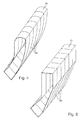
Figur 4 zeigt eine Anordnung mehrerer
Lichtleitervorrichtungen mit einer ersten Ausgestaltung von Lichtaustrittsflächen 20. Die Lichtaustrittsflächen 20 sind hier in einer Raumrichtung walzen-artig konvex gekrümmt und weisen in der anderen Raumrichtung keine Krümmung auf. Die Lichtleitermodule 66 zeichnen sich durch einen im Raum gekrümmten Verlauf aus, wobei ihr Querschnitt in der dargestellten Ausgestaltung jeweils über ihre ganze Länge rechteckig ist. -
Figur 5 zeigt eine Anordnung mehrerer
Lichtleitervorrichtungen 66 mit rechteckig-ebenen Lichtaustrittsflächen 20. Die Lichtleitermodule 66 derFig. 5 zeichnen sich durch einen im Raum geknickten Verlauf aus. Auch hier gilt, dass ihr Querschnitt in der dargestellten Ausgestaltung jeweils über ihre ganze Länge rechteckig ist. - Wesentlich ist sowohl beim Gegenstand der
Fig. 4 als auch beim Gegenstand derFig. 5 , dass es sich jeweils um glatte Lichtaustrittsflächen 20 handelt, was dadurch ermöglicht wird, dass die lichtverteilungs-erzeugende Optik gerade nicht in der Lichtaustrittsfläche 20 angeordnet ist. Die Form der Lichtaustrittsfläche 20 ist in Abhängigkeit von der geforderten Lichtverteilung und von gestalterischen Anforderungen frei wählbar und kann zum Beispiel auch Kissen-artig hervorgewölbt, also in zwei Raumrichtungen konvex, oder in einer oder zwei Raumrichtungen konkav, oder in eine Raumrichtung konkav und in der anderen Raumrichtung konvex, usw. sein. - Die Lichtleitervorrichtungen 66 der
Figuren 4 und/oder 5 entsprechen im Übrigen den Lichtleitervorrichtungen 10, 48 oder 54, wie sie in dieser Anmeldung vorgestellt worden sind. - Das aus den
Figuren 4 und 5 ersichtliche Zusammensetzen von Lichtleitervorrichtungen 66 aus einer Mehrzahl von einzelnen in dieser Anmeldung vorgestellten Lichtleitervorrichtungen, die selbst modulartig aufgebaut sind, eröffnet dem Gestalter und Konstrukteur die Möglichkeit, eine Vielzahl unterschiedlicher Beleuchtungseinrichtungen und Lichtfunktionen unter Rückgriff auf eine überschaubare Anzahl von Komponenten anzubieten. -
Figur 6 zeigt im Teil 3a einen Querschnitt VI-VI durch ein Lichtleitermodul 14 mit rechteckigem Querschnitt und im Teil 3b einen vergleichbaren schiefwinkligen Querschnitt.
Die Pfeile 68, 70 stellen jeweils in den
Querschnittsflächen liegende Richtungskomponenten eines einzelnen Lichtstrahls im Lichtleitermodul 14 dar. Ein solcher Lichtstrahl besitzt auch eine senkrecht zur Zeichenebene gerichtete Komponente, so dass die Pfeile 68, 70 zum Beispiel als Komponenten des im Lichtleitermodul propagierenden Lichts 26 betrachtet werden können. Wie ein Vergleich derFiguren 6a und 6b zeigt, läuft die Komponente 68 immer auf dem gleichen Pfad durch den rechtwinkligen Querschnitt des Lichtleitermoduls aus derFig. 6a , während die Komponente 70 bei jedem Umlauf einen neuen Pfad im Lichtleitermodul mit dem schiefwinkligen Querschnitt derFig. 6b bildet. Das bedeutet, dass eine zum Beispiel beim Eintritt in das Lichtleitermodul 14 erzeugte Lichtverteilung im Fall des rechteckigen Querschnitts erhalten bleibt, während sie im Fall des schiefwinkligen Querschnitts ausFigur 6b mit zunehmendem Abstand von der lichtverteilungserzeugenden Fläche verändert wird. - Die Lichtverteilung bleibt zumindest im Wesentlichen erhalten, wenn das Lichtleitermodul zwar nicht mehr ideal rechteckig, aber zumindest noch nahezu rechteckig ist. Dabei gilt ein Lichtleitermodul dann als nahezu rechteckig, wenn sein Umfang zu wenigstens 90% aus zwei Paaren von jeweils zueinander parallelen Geraden besteht, wobei die Geraden eines Paars orthogonal zu den Geraden des anderen Paars angeordnet sind. Bis zu 10% der Länge können zum Beispiel für gebrochene Kanten an den Ecken verbraucht werden.
-
Figur 7 zeigt Draufsichten auf verschiedene Ausgestaltungen einer lichtverteilungserzeugenden Fläche, zum Beispiel der Einkoppelfläche 18 aus derFigur 1 , der Fläche 52 aus derFigur 2 und der Fläche 58 aus derFigur 3 .Figur 7a zeigt eine matrixartige Anordnung von Streuoptiken 70, wobei die Zeilen parallel zu zwei parallelen Kanten des rechteckigen Querschnitts des Lichtleiters und die Spalten zu den beiden anderen parallelen Kanten des rechteckigen Querschnitts des Lichtleiters parallel sind. Diese Streuoptiken besitzen bevorzugt eine Kissen-artig gekrümmte Oberfläche, ohne dass die Erfindung auf eine solche spezielle Ausgestaltung beschränkt ist. Unter einer Kissen-artig gekrümmten Fläche wird hier eine in zwei Raumrichtungen konkav oder konvex gekrümmte Fläche verstanden. Alternativ oder ergänzend zu Kissen-artig gekrümmten Oberflächen können auch andere geometrische Formen wie Prismen, Keile, Linsen oder Walzen verwendet werden. - Die Streuoptiken 70 können alternativ auch diagonal zur rechteckigen Fläche des Lichtleiters angeordnet sein. Eine Ausgestaltung einer solchen Anordnung ist in der
Fig. 7b dargestellt. Eine ringförmige Anordnung, wie Sie in derFigur 7c dargestellt ist, kann ebenfalls verwendet werden. - Es hängt letztlich von der zu erzeugenden Lichtverteilung ab, welche Ausgestaltung in einem konkreten Fall zu empfehlen ist. Alternativ zur Erzeugung der Lichtverteilung durch Streuoptiken, die in einer Fläche angeordnet sind, können die Lichtverteilungen auch durch Streuoptiken erzeugt werden, die in mehreren Flächen angeordnet sind.
- Für die Anordnung, wie sie in der
Figur 1 dargestellt ist, ist es zum Beispiel denkbar, Walzenstrukturen in der Lichteintrittsfläche des Lichtleitermoduls 14 und zusätzliche Walzenstrukturen in der Lichtaustrittsfläche des Einkoppelmoduls 12 zu verwenden, wobei die Walzenstrukturen in der einen Fläche in einer Ausgestaltung parallel zu den Walzenstrukturen in der anderen Fläche angeordnet sind. In einer alternativen Ausgestaltung schließt die Ausrichtung der Walzenstrukturen in der einen Fläche mit der Ausrichtung der Walzenstrukturen in der anderen Fläche einen Winkel ein. Dabei ist insbesondere eine orthogonal gekreuzte Anordnung bevorzugt. - Die hier vorgestellten Lichtleitervorrichtungen werden bevorzugt in Kraftfahrzeugbeleuchtungseinrichtungen verwendet, wobei die Stirnflächen als sichtbar leuchtende Flächen dienen und wobei die Einkoppelmodule 12 und gegebenenfalls den Einkoppelmodulen 12 benachbarte erste Abschnitte der Lichtleitermodule durch Blenden und/oder eine Abdeckrahmen gegen Einblicke von außen abgedeckt sind.
Claims (13)
- Lichtleitervorrichtung (10), die zu einer Verwendung in einer Kraftfahrzeugbeleuchtungseinrichtung eingerichtet ist und die ein Einkoppelmodul (12), ein von dem Einkoppelmodul (12) baulich getrenntes Lichtleitermodul (14) sowie eine Optik (16) zur Beeinflussung einer Lichtverteilung aufweist, deren Einfluss auf die Menge an ausgekoppeltem Licht (46) vernachlässigbar ist, wobei das Lichtleitermodul (14) eine erste Stirnfläche und eine zweite Stirnfläche (18) aufweist, die von der ersten Stirnfläche (20) durch eine Mantelfläche (22) getrennt ist, wobei die erste Stirnfläche (18) dazu eingerichtet ist, vom Einkoppelmodul (12) ausgehendes Licht (24) in das Lichtleitermodul (14) aufzunehmen, und wobei die zweite Stirnfläche (20) dazu eingerichtet ist, über die erste Stirnfläche (18) aufgenommenes Licht (26) aus dem Lichtleitermodul (14) austreten zu lassen, dadurch gekennzeichnet, dass die Optik (16) zur Beeinflussung der Lichtverteilung an einer von der zweiten Stirnfläche (20) verschiedenen Fläche (18) der Lichtleitervorrichtung (10) angeordnet ist.
- Lichtleitervorrichtung (10) nach Anspruch 1, dadurch gekennzeichnet, dass das Einkoppelmodul (12) ein Lichtquellenmodul (28) und ein Optikmodul (30) aufweist.
- Lichtleitervorrichtung (10) nach einem der vorhergehenden Ansprüche, dadurch gekennzeichnet, dass das Einkoppelmodul (12) dazu eingerichtet ist, paralleles und homogen über eine Lichtaustrittsfläche (42) des Einkoppelmoduls (12) verteiltes Licht zu erzeugen.
- Lichtleitervorrichtung (10) nach einem der vorhergehenden Ansprüche, dadurch gekennzeichnet, dass die Optik (16) zur Beeinflussung der Lichtverteilung in der ersten Stirnfläche (18) angeordnet ist.
- Lichtleitervorrichtung (48) nach einem der vorhergehenden Ansprüche, dadurch gekennzeichnet, dass die Optik (52) zur Beeinflussung der Lichtverteilung in der Mantelfläche (22) angeordnet ist.
- Lichtleitervorrichtung (54) nach einem der vorhergehenden Ansprüche, dadurch gekennzeichnet, dass die Optik (56) zur Beeinflussung der Lichtverteilung in einer Lichtaustrittsfläche (58) des Einkoppelmoduls (12) angeordnet ist.
- Lichtleitervorrichtung (10; 48; 54) nach einem der vorhergehenden Ansprüche, dadurch gekennzeichnet, dass die Optik (16; 52; 56) zur Beeinflussung der Lichtverteilung Streuoptiken aufweist, die das Licht beim Passieren der Streuoptiken oder bei einer Reflexion an den Stirnoptiken in durch die Form und Anordnung der Streuoptiken vorbestimmte Richtungen brechen oder reflektieren.
- Lichtleitervorrichtung (10; 48; 54) nach einem der vorhergehenden Ansprüche, dadurch gekennzeichnet, dass die Streuoptiken eine Kissen-artig gekrümmte Oberfläche besitzen.
- Lichtleitervorrichtung(10; 48; 54) nach einem der vorhergehenden Ansprüche, dadurch gekennzeichnet, dass die zweite Stirnfläche (20) einen rechteckigen Querschnitt aufweist.
- Lichtleitervorrichtung (10; 48; 54) nach einem der vorhergehenden Ansprüche, dadurch gekennzeichnet, dass die zweite Stirnfläche eben ist.
- Lichtleitervorrichtung (10; 48; 54) nach einem der vorhergehenden Ansprüche, dadurch gekennzeichnet, dass die zweite Stirnfläche (20) eine im Raum gekrümmte Oberfläche aufweist.
- Lichtleitervorrichtung (10; 40; 54) nach einem der vorhergehenden Ansprüche, dadurch gekennzeichnet, dass ihr Lichtleitermodul (14; 50; 60) einen im Raum gekrümmten oder geknickten Verlauf aufweist.
- Lichtleitervorrichtung (10; 40; 54) nach einem der vorhergehenden Ansprüche, dadurch gekennzeichnet, dass ihr Lichtleitermodul (14; 50; 60) über seine ganze Länge rechteckig oder nahezu rechteckig ist.
Applications Claiming Priority (1)
| Application Number | Priority Date | Filing Date | Title |
|---|---|---|---|
| DE102010013931A DE102010013931A1 (de) | 2010-04-06 | 2010-04-06 | Modulare Lichtleitervorrichtung für Kraftfahrzeugbeleuchtungseinrichtungen |
Publications (2)
| Publication Number | Publication Date |
|---|---|
| EP2378187A1 true EP2378187A1 (de) | 2011-10-19 |
| EP2378187B1 EP2378187B1 (de) | 2018-06-06 |
Family
ID=44202127
Family Applications (1)
| Application Number | Title | Priority Date | Filing Date |
|---|---|---|---|
| EP11155014.1A Active EP2378187B1 (de) | 2010-04-06 | 2011-02-18 | Modulare Lichtleitervorrichtung für Kraftfahrzeugbeleuchtungseinrichtungen |
Country Status (3)
| Country | Link |
|---|---|
| EP (1) | EP2378187B1 (de) |
| CN (1) | CN102252262B (de) |
| DE (1) | DE102010013931A1 (de) |
Cited By (15)
| Publication number | Priority date | Publication date | Assignee | Title |
|---|---|---|---|---|
| WO2014199108A1 (fr) * | 2013-06-14 | 2014-12-18 | Automotive Lighting Rear Lamps France | Module d'éclairage pour automobiles à homogénéité de lumière à évolution continue |
| WO2014203061A3 (en) * | 2013-06-18 | 2015-03-26 | Koito Manufacturing Co., Ltd. | Vehicular lamp |
| DE102015213827A1 (de) * | 2015-07-22 | 2017-01-26 | Automotive Lighting Reutlingen Gmbh | Vorsatzoptik für eine Signalleuchte einer Kraftfahrzeugbeleuchtungseinrichtung |
| WO2017015684A1 (de) * | 2015-07-28 | 2017-02-02 | Zkw Group Gmbh | Leuchteinrichtung für einen kfz-scheinwerfer |
| ITUA20161588A1 (it) * | 2016-03-11 | 2017-09-11 | Bevilacqua Carlotta Francesca Isolina Maria De | Elemento ottico di trasmissione e distribuzione della luce e dispositivo di illuminazione comprendente tale elemento ottico |
| DE102016007709A1 (de) * | 2016-06-23 | 2017-12-28 | Daimler Ag | Kraftfahrzeugzierteil |
| AT518951A1 (de) * | 2016-08-03 | 2018-02-15 | Zkw Group Gmbh | Verfahren zum Einstellen eines von einer Kraftfahrzeugbeleuchtungsvorrichtung abgestrahlten Lichtstroms und eine Kraftfahrzeugbeleuchtungsvorrichtung zum Abstrahlen des eingestellten Lichtstroms |
| EP2708800A3 (de) * | 2012-09-13 | 2018-04-04 | Koito Manufacturing Co., Ltd. | Fahrzeuglampe |
| EP2746647A3 (de) * | 2012-12-21 | 2018-04-11 | Flex-N-Gate Advanced Product Development, LLC | Lichtleiter mit gleichmäßiger Beleuchtungsintensität |
| WO2018189086A1 (en) * | 2017-04-14 | 2018-10-18 | HELLA GmbH & Co. KGaA | Method and apparatus to improve the homogeneity of an edge-light |
| DE102018104124A1 (de) * | 2018-02-23 | 2019-08-29 | Automotive Lighting Reutlingen Gmbh | Leuchtenmodul für ein Kraftfahrzeug |
| DE102018113151A1 (de) | 2018-06-01 | 2019-12-05 | Automotive Lighting Reutlingen Gmbh | Leuchtenmodul für eine Kraftfahrzeugleuchte |
| EP3674138A1 (de) * | 2018-12-26 | 2020-07-01 | Excellence Optoelectronics Inc. | Led-linearbeleuchtungsmodul für fahrzeuge |
| WO2022179988A1 (en) * | 2021-02-24 | 2022-09-01 | Valeo Vision | Light-emitting device, vehicle lamp and vehicle |
| WO2025252646A1 (fr) * | 2024-06-04 | 2025-12-11 | Valeo Vision | Guide de lumière comprenant une surface de réflexion pourvue d'une pluralité de facettes adjacentes |
Families Citing this family (32)
| Publication number | Priority date | Publication date | Assignee | Title |
|---|---|---|---|---|
| DE102012005399A1 (de) * | 2012-03-16 | 2013-09-19 | Audi Ag | Beleuchtungseinrichtung, insbesondere Konturbeleuchtung für ein Kraftfahrzeug |
| DE102012005398A1 (de) * | 2012-03-16 | 2013-09-19 | Audi Ag | Beleuchtungseinrichtung, insbesondere Konturbeleuchtung für ein Kraftfahrzeug |
| DE102012211284A1 (de) * | 2012-06-29 | 2014-01-02 | Automotive Lighting Reutlingen Gmbh | Lichtleitelement und Lichtleiter |
| DE102012213843B3 (de) * | 2012-08-03 | 2013-09-19 | Automotive Lighting Reutlingen Gmbh | Primäroptikeinheit für ein Lichtmodul |
| DE102012107437B4 (de) * | 2012-08-14 | 2022-04-28 | HELLA GmbH & Co. KGaA | Leuchtvorrichtung |
| DE102012108855B4 (de) * | 2012-09-20 | 2025-10-09 | HELLA GmbH & Co. KGaA | Lichtleiter für Fahrzeuge |
| DE102012111313B4 (de) * | 2012-11-23 | 2023-09-28 | HELLA GmbH & Co. KGaA | Beleuchtungseinheit für ein Kraftfahrzeug |
| DE102012111666A1 (de) * | 2012-11-30 | 2014-06-05 | Osram Opto Semiconductors Gmbh | Beleuchtungseinrichtung |
| DE102012112152A1 (de) * | 2012-12-12 | 2014-06-12 | Dr. Ing. H.C. F. Porsche Aktiengesellschaft | Kraftfahrzeugrückleuchte |
| DE102012112125A1 (de) * | 2012-12-12 | 2014-06-12 | Hella Kgaa Hueck & Co. | Beleuchtungsvorrichtung für Fahrzeuge |
| DE102013212355B4 (de) | 2013-06-26 | 2018-07-19 | Automotive Lighting Reutlingen Gmbh | Kraftfahrzeugbeleuchtungseinrichtung mit einem eine Einkoppeloptik und eine Transport- und Umformoptik aufweisenden Lichtleiter |
| DE102013107912B4 (de) * | 2013-07-24 | 2023-07-27 | HELLA GmbH & Co. KGaA | Beleuchtungsvorrichtung für Fahrzeuge |
| CN104456163A (zh) * | 2013-09-23 | 2015-03-25 | 欧普照明股份有限公司 | 一种装饰灯及装饰灯用光学模组 |
| DE102013222363B3 (de) * | 2013-11-04 | 2015-04-02 | Automotive Lighting Reutlingen Gmbh | Lichtleiter |
| DE102014110347B4 (de) * | 2014-07-23 | 2025-12-11 | Dr. Ing. H.C. F. Porsche Aktiengesellschaft | Lichtleiteinrichtung |
| JP6622965B2 (ja) * | 2015-01-06 | 2019-12-18 | 株式会社小糸製作所 | 車輌用灯具 |
| DE102015103660A1 (de) * | 2015-03-12 | 2016-09-15 | Rehau Ag + Co | Leuchtvorrichtung mit einer Lichtleiterplatte |
| DE102015218134A1 (de) * | 2015-09-22 | 2017-03-23 | Automotive Lighting Reutlingen Gmbh | Leuchten-Lichtmodul für ein Kraftfahrzeug |
| DE102015222495A1 (de) | 2015-11-13 | 2017-05-18 | Automotive Lighting Reutlingen Gmbh | Vorsatzoptik und Vorsatzoptikanordnung mit mehreren Vorsatzoptiken |
| AT518090B1 (de) * | 2015-12-21 | 2017-10-15 | Zkw Group Gmbh | Scheinwerfer für ein Fahrzeug |
| DE102017206194A1 (de) * | 2017-04-11 | 2018-10-11 | Osram Gmbh | Lichtleiter, Optik, Beleuchtungssytem und Scheinwerfer |
| DE102017207225A1 (de) * | 2017-04-28 | 2018-10-31 | Volkswagen Aktiengesellschaft | Beleuchtbares Säulenverkleidungsbauteil für eine Kraftfahrzeugkarosserie |
| CN107246580A (zh) * | 2017-08-09 | 2017-10-13 | 上海小糸车灯有限公司 | 一种车灯厚壁聚光器发光结构 |
| DE102017119500A1 (de) * | 2017-08-25 | 2019-02-28 | Dr. Ing. H.C. F. Porsche Aktiengesellschaft | Beleuchtungseinrichtung |
| CN107893963B (zh) * | 2017-11-15 | 2024-05-03 | 华域视觉科技(上海)有限公司 | 车辆用灯具光学系统 |
| DE102018203810A1 (de) * | 2018-03-13 | 2019-09-19 | Osram Gmbh | Asymmetrische lichtleiteranordnung |
| EP3572719A1 (de) * | 2018-05-25 | 2019-11-27 | ZKW Group GmbH | Lichtmodul für einen kfz-scheinwerfer |
| EP3667389B1 (de) * | 2018-12-11 | 2023-03-15 | ZKW Group GmbH | Beleuchtungsvorrichtung für ein kraftfahrzeug |
| DE102020104567A1 (de) | 2020-02-21 | 2021-08-26 | HELLA GmbH & Co. KGaA | Beleuchtungseinrichtung für ein Kraftfahrzeug |
| DE102020108338A1 (de) | 2020-03-26 | 2021-09-30 | Marelli Automotive Lighting Reutlingen (Germany) GmbH | Beleuchtungseinrichtung mit einem Lichtleiter und einem Lichteinkoppelmodul |
| EP4257872B1 (de) * | 2022-04-05 | 2024-12-04 | ZKW Group GmbH | Optikvorrichtung für einen kraftfahrzeugscheinwerfer |
| DE102023116195A1 (de) * | 2023-06-21 | 2024-12-24 | HELLA GmbH & Co. KGaA | Beleuchtungsvorrichtung für Fahrzeuge |
Citations (6)
| Publication number | Priority date | Publication date | Assignee | Title |
|---|---|---|---|---|
| US6036340A (en) * | 1998-03-03 | 2000-03-14 | Ford Global Technologies, Inc. | Dimpled manifold optical element for a vehicle lighting system |
| DE10153543A1 (de) * | 2001-10-30 | 2003-05-15 | Hella Kg Hueck & Co | Beleuchtungseinrichtung für Fahrzeuge |
| US20070019429A1 (en) | 2005-07-21 | 2007-01-25 | Valeo Vision | Lighting or indicator device, in particular for motor vehicles |
| DE102006032373A1 (de) * | 2006-07-13 | 2008-01-17 | Automotive Lighting Reutlingen Gmbh | Leuchtenanordnung für einen Kraftfahrzeugscheinwerfer oder eine Kraftfahrzeugheckleuchte |
| DE102008008180A1 (de) * | 2008-02-08 | 2009-08-27 | Audi Ag | Kraftfahrzeugbeleuchtungseinrichtung |
| US20100008088A1 (en) * | 2008-07-10 | 2010-01-14 | Koito Manufacturing Co., Ltd. | Lamp |
Family Cites Families (2)
| Publication number | Priority date | Publication date | Assignee | Title |
|---|---|---|---|---|
| JP4339143B2 (ja) * | 2004-02-10 | 2009-10-07 | 株式会社小糸製作所 | 車両用灯具ユニット |
| JP4524265B2 (ja) * | 2005-03-30 | 2010-08-11 | 三星電子株式会社 | 照明ユニット及びそれを採用した画像投射装置 |
-
2010
- 2010-04-06 DE DE102010013931A patent/DE102010013931A1/de not_active Withdrawn
-
2011
- 2011-02-18 EP EP11155014.1A patent/EP2378187B1/de active Active
- 2011-04-06 CN CN201110087397.9A patent/CN102252262B/zh not_active Expired - Fee Related
Patent Citations (6)
| Publication number | Priority date | Publication date | Assignee | Title |
|---|---|---|---|---|
| US6036340A (en) * | 1998-03-03 | 2000-03-14 | Ford Global Technologies, Inc. | Dimpled manifold optical element for a vehicle lighting system |
| DE10153543A1 (de) * | 2001-10-30 | 2003-05-15 | Hella Kg Hueck & Co | Beleuchtungseinrichtung für Fahrzeuge |
| US20070019429A1 (en) | 2005-07-21 | 2007-01-25 | Valeo Vision | Lighting or indicator device, in particular for motor vehicles |
| DE102006032373A1 (de) * | 2006-07-13 | 2008-01-17 | Automotive Lighting Reutlingen Gmbh | Leuchtenanordnung für einen Kraftfahrzeugscheinwerfer oder eine Kraftfahrzeugheckleuchte |
| DE102008008180A1 (de) * | 2008-02-08 | 2009-08-27 | Audi Ag | Kraftfahrzeugbeleuchtungseinrichtung |
| US20100008088A1 (en) * | 2008-07-10 | 2010-01-14 | Koito Manufacturing Co., Ltd. | Lamp |
Cited By (30)
| Publication number | Priority date | Publication date | Assignee | Title |
|---|---|---|---|---|
| EP2708800A3 (de) * | 2012-09-13 | 2018-04-04 | Koito Manufacturing Co., Ltd. | Fahrzeuglampe |
| EP2746647A3 (de) * | 2012-12-21 | 2018-04-11 | Flex-N-Gate Advanced Product Development, LLC | Lichtleiter mit gleichmäßiger Beleuchtungsintensität |
| WO2014199108A1 (fr) * | 2013-06-14 | 2014-12-18 | Automotive Lighting Rear Lamps France | Module d'éclairage pour automobiles à homogénéité de lumière à évolution continue |
| WO2014203061A3 (en) * | 2013-06-18 | 2015-03-26 | Koito Manufacturing Co., Ltd. | Vehicular lamp |
| DE102015213827A1 (de) * | 2015-07-22 | 2017-01-26 | Automotive Lighting Reutlingen Gmbh | Vorsatzoptik für eine Signalleuchte einer Kraftfahrzeugbeleuchtungseinrichtung |
| DE102015213827B4 (de) * | 2015-07-22 | 2021-03-18 | Automotive Lighting Reutlingen Gmbh | Vorsatzoptik für eine Signalleuchte einer Kraftfahrzeugbeleuchtungseinrichtung |
| US10018317B2 (en) | 2015-07-28 | 2018-07-10 | Zkw Group Gmbh | Lighting device for a motor vehicle headlamp |
| WO2017015684A1 (de) * | 2015-07-28 | 2017-02-02 | Zkw Group Gmbh | Leuchteinrichtung für einen kfz-scheinwerfer |
| AT517523A9 (de) * | 2015-07-28 | 2017-05-15 | Zkw Group Gmbh | Leuchteinrichtung für einen KFZ-Scheinwerfer |
| AT517523B1 (de) * | 2015-07-28 | 2017-09-15 | Zkw Group Gmbh | Leuchteinrichtung für einen KFZ-Scheinwerfer |
| ITUA20161588A1 (it) * | 2016-03-11 | 2017-09-11 | Bevilacqua Carlotta Francesca Isolina Maria De | Elemento ottico di trasmissione e distribuzione della luce e dispositivo di illuminazione comprendente tale elemento ottico |
| DE102016007709B4 (de) | 2016-06-23 | 2023-02-02 | Mercedes-Benz Group AG | Kraftfahrzeugzierteil |
| DE102016007709A1 (de) * | 2016-06-23 | 2017-12-28 | Daimler Ag | Kraftfahrzeugzierteil |
| US10513222B2 (en) | 2016-06-23 | 2019-12-24 | Daimler Ag | Motor vehicle trim part with illumination |
| AT518951B1 (de) * | 2016-08-03 | 2020-01-15 | Zkw Group Gmbh | Verfahren zum Einstellen eines von einer Kraftfahrzeugbeleuchtungsvorrichtung abgestrahlten Lichtstroms und eine Kraftfahrzeugbeleuchtungsvorrichtung zum Abstrahlen des eingestellten Lichtstroms |
| AT518951A1 (de) * | 2016-08-03 | 2018-02-15 | Zkw Group Gmbh | Verfahren zum Einstellen eines von einer Kraftfahrzeugbeleuchtungsvorrichtung abgestrahlten Lichtstroms und eine Kraftfahrzeugbeleuchtungsvorrichtung zum Abstrahlen des eingestellten Lichtstroms |
| CN110678691B (zh) * | 2017-04-14 | 2022-03-25 | 黑拉有限责任两合公司 | 用于改善边缘灯的均匀性的方法和装置 |
| WO2018189086A1 (en) * | 2017-04-14 | 2018-10-18 | HELLA GmbH & Co. KGaA | Method and apparatus to improve the homogeneity of an edge-light |
| DE112018001981B4 (de) * | 2017-04-14 | 2025-07-03 | HELLA GmbH & Co. KGaA | Leuchtvorrichtung umfassend einen rechteckigen plattenförmigen lichtausbreitungabschnitt mit muschelförmigen konvexen strukturen zum streuen und mischen des sich darin ausbreitenden lichts an seinen beiden flachseiten |
| CN110678691A (zh) * | 2017-04-14 | 2020-01-10 | 黑拉有限责任两合公司 | 用于改善边缘灯的均匀性的方法和装置 |
| US11143379B2 (en) | 2017-04-14 | 2021-10-12 | HELLA GmbH & Co. KGaA | Method and apparatus to improve the homogeneity of an edge-light |
| DE102018104124A1 (de) * | 2018-02-23 | 2019-08-29 | Automotive Lighting Reutlingen Gmbh | Leuchtenmodul für ein Kraftfahrzeug |
| DE102018104124B4 (de) * | 2018-02-23 | 2025-05-28 | Automotive Lighting Reutlingen Gmbh | Leuchtenmodul für ein Kraftfahrzeug |
| DE102018113151A1 (de) | 2018-06-01 | 2019-12-05 | Automotive Lighting Reutlingen Gmbh | Leuchtenmodul für eine Kraftfahrzeugleuchte |
| DE102018113151B4 (de) | 2018-06-01 | 2023-10-19 | Automotive Lighting Reutlingen Gmbh | Leuchtenmodul für eine Kraftfahrzeugleuchte |
| EP3674138A1 (de) * | 2018-12-26 | 2020-07-01 | Excellence Optoelectronics Inc. | Led-linearbeleuchtungsmodul für fahrzeuge |
| WO2022179988A1 (en) * | 2021-02-24 | 2022-09-01 | Valeo Vision | Light-emitting device, vehicle lamp and vehicle |
| JP2024507921A (ja) * | 2021-02-24 | 2024-02-21 | ヴァレオ ビジョン | 発光装置、車両ランプ、および車両 |
| US12196388B2 (en) | 2021-02-24 | 2025-01-14 | Valeo Vision | Light-emitting device, vehicle lamp and vehicle |
| WO2025252646A1 (fr) * | 2024-06-04 | 2025-12-11 | Valeo Vision | Guide de lumière comprenant une surface de réflexion pourvue d'une pluralité de facettes adjacentes |
Also Published As
| Publication number | Publication date |
|---|---|
| CN102252262B (zh) | 2016-05-04 |
| CN102252262A (zh) | 2011-11-23 |
| EP2378187B1 (de) | 2018-06-06 |
| DE102010013931A1 (de) | 2011-10-06 |
Similar Documents
| Publication | Publication Date | Title |
|---|---|---|
| EP2378187B1 (de) | Modulare Lichtleitervorrichtung für Kraftfahrzeugbeleuchtungseinrichtungen | |
| DE102012202508B4 (de) | Lichtleitervorrichtung für eine Kraftfahrzeugleuchte | |
| DE102012224079B4 (de) | Lichtleiter mit einer bandförmigen Lichtaustrittsfläche | |
| EP2607774B1 (de) | Kraftfahrzeugbeleuchtungseinrichtung mit einer langen und flachen leuchtenden Fläche | |
| EP3084292B1 (de) | Kraftfahrzeugleuchte mit einem lichtleiter | |
| DE102013227195A1 (de) | Kraftfahrzeugleuchte mit einem linien- oder flächenhaften Erscheinungsbild | |
| EP2803905B1 (de) | Kraftfahrzeugbeleuchtungseinrichtung mit einer Lichtleiteranordnung | |
| EP3118060A1 (de) | Lichtleiteranordnung zur erzeugung von zumindest einer beleuchtungsfunktion und/oder signalisierungsfunktion eines kraftfahrzeugscheinwerfers | |
| EP2618045A1 (de) | Beleuchtungseinrichtung für ein Kraftfahrzeug | |
| AT517105A4 (de) | Lichtleiteranordnung zur Erzeugung von zumindest einer Beleuchtungsfunktion und/oder Signalisierungsfunktion eines Kraftfahrzeugscheinwerfers | |
| AT517413A1 (de) | Lichtleiteranordnung zur Erzeugung von zumindest einer Beleuchtungsfunktion und/oder Signalisierungsfunktion eines Kraftfahrzeugscheinwerfers | |
| DE102010025208A1 (de) | Kraftfahrzeugbeleuchtungseinrichtung mit einem langgestreckten Lichtleiter | |
| DE102017115899A1 (de) | Kraftfahrzeugleuchte und Kraftfahrzeugscheinwerfer mit einer solchen Leuchte | |
| DE112019007335T5 (de) | Linse zum Erzeugen einer Abblendlicht-III-Zonen-Lichtform, Fahrzeugbeleuchtungseinrichtung und Fahrzeug | |
| EP2500753B1 (de) | Lichtleiter mit direkt Licht auskoppelnden Auskoppelelementen | |
| EP3531012A1 (de) | Beleuchtungseinrichtung für kraftfahrzeuge mit einem langgestreckten lichtleiter | |
| EP2371623B1 (de) | Flächiger Lichtleiter zur Strahlkollimierung | |
| EP2927572A1 (de) | Kraftfahrzeugleuchte mit Wischeffekt | |
| EP3812653B1 (de) | Signalleuchte mit einem lichtleiter | |
| EP3461687A1 (de) | Lichtleiteranordnung einer kraftfahrzeugleuchte und kraftfahrzeugleuchte mit einer solchen lichtleiteranordnung | |
| DE102015210372B4 (de) | Signallichtmodul für ein Kraftfahrzeug | |
| DE102019118005A1 (de) | Kraftfahrzeugbeleuchtungseinrichtung mit einer Lichtleiterplatte | |
| EP3550205A1 (de) | Lichtleiter für ein kraftfahrzeuglichtmodul | |
| DE10247328B3 (de) | Fahrzeugleuchte mit vergleichmäßigter Lichtverteilung | |
| DE202015001004U1 (de) | Eine Endlosspiegelanordnung aufweisende Beleuchtungsvorrichtung für ein Kraftfahrzeug |
Legal Events
| Date | Code | Title | Description |
|---|---|---|---|
| AK | Designated contracting states |
Kind code of ref document: A1 Designated state(s): AL AT BE BG CH CY CZ DE DK EE ES FI FR GB GR HR HU IE IS IT LI LT LU LV MC MK MT NL NO PL PT RO RS SE SI SK SM TR |
|
| AX | Request for extension of the european patent |
Extension state: BA ME |
|
| PUAI | Public reference made under article 153(3) epc to a published international application that has entered the european phase |
Free format text: ORIGINAL CODE: 0009012 |
|
| 17P | Request for examination filed |
Effective date: 20120418 |
|
| 17Q | First examination report despatched |
Effective date: 20141027 |
|
| GRAP | Despatch of communication of intention to grant a patent |
Free format text: ORIGINAL CODE: EPIDOSNIGR1 |
|
| STAA | Information on the status of an ep patent application or granted ep patent |
Free format text: STATUS: GRANT OF PATENT IS INTENDED |
|
| INTG | Intention to grant announced |
Effective date: 20180104 |
|
| GRAS | Grant fee paid |
Free format text: ORIGINAL CODE: EPIDOSNIGR3 |
|
| GRAA | (expected) grant |
Free format text: ORIGINAL CODE: 0009210 |
|
| STAA | Information on the status of an ep patent application or granted ep patent |
Free format text: STATUS: THE PATENT HAS BEEN GRANTED |
|
| AK | Designated contracting states |
Kind code of ref document: B1 Designated state(s): AL AT BE BG CH CY CZ DE DK EE ES FI FR GB GR HR HU IE IS IT LI LT LU LV MC MK MT NL NO PL PT RO RS SE SI SK SM TR |
|
| REG | Reference to a national code |
Ref country code: GB Ref legal event code: FG4D Free format text: NOT ENGLISH |
|
| REG | Reference to a national code |
Ref country code: CH Ref legal event code: EP Ref country code: AT Ref legal event code: REF Ref document number: 1006486 Country of ref document: AT Kind code of ref document: T Effective date: 20180615 |
|
| REG | Reference to a national code |
Ref country code: IE Ref legal event code: FG4D Free format text: LANGUAGE OF EP DOCUMENT: GERMAN |
|
| REG | Reference to a national code |
Ref country code: DE Ref legal event code: R096 Ref document number: 502011014280 Country of ref document: DE |
|
| REG | Reference to a national code |
Ref country code: NL Ref legal event code: MP Effective date: 20180606 |
|
| REG | Reference to a national code |
Ref country code: LT Ref legal event code: MG4D |
|
| PG25 | Lapsed in a contracting state [announced via postgrant information from national office to epo] |
Ref country code: NO Free format text: LAPSE BECAUSE OF FAILURE TO SUBMIT A TRANSLATION OF THE DESCRIPTION OR TO PAY THE FEE WITHIN THE PRESCRIBED TIME-LIMIT Effective date: 20180906 Ref country code: BG Free format text: LAPSE BECAUSE OF FAILURE TO SUBMIT A TRANSLATION OF THE DESCRIPTION OR TO PAY THE FEE WITHIN THE PRESCRIBED TIME-LIMIT Effective date: 20180906 Ref country code: LT Free format text: LAPSE BECAUSE OF FAILURE TO SUBMIT A TRANSLATION OF THE DESCRIPTION OR TO PAY THE FEE WITHIN THE PRESCRIBED TIME-LIMIT Effective date: 20180606 Ref country code: FI Free format text: LAPSE BECAUSE OF FAILURE TO SUBMIT A TRANSLATION OF THE DESCRIPTION OR TO PAY THE FEE WITHIN THE PRESCRIBED TIME-LIMIT Effective date: 20180606 Ref country code: SE Free format text: LAPSE BECAUSE OF FAILURE TO SUBMIT A TRANSLATION OF THE DESCRIPTION OR TO PAY THE FEE WITHIN THE PRESCRIBED TIME-LIMIT Effective date: 20180606 Ref country code: ES Free format text: LAPSE BECAUSE OF FAILURE TO SUBMIT A TRANSLATION OF THE DESCRIPTION OR TO PAY THE FEE WITHIN THE PRESCRIBED TIME-LIMIT Effective date: 20180606 Ref country code: CY Free format text: LAPSE BECAUSE OF FAILURE TO SUBMIT A TRANSLATION OF THE DESCRIPTION OR TO PAY THE FEE WITHIN THE PRESCRIBED TIME-LIMIT Effective date: 20180606 |
|
| PG25 | Lapsed in a contracting state [announced via postgrant information from national office to epo] |
Ref country code: LV Free format text: LAPSE BECAUSE OF FAILURE TO SUBMIT A TRANSLATION OF THE DESCRIPTION OR TO PAY THE FEE WITHIN THE PRESCRIBED TIME-LIMIT Effective date: 20180606 Ref country code: RS Free format text: LAPSE BECAUSE OF FAILURE TO SUBMIT A TRANSLATION OF THE DESCRIPTION OR TO PAY THE FEE WITHIN THE PRESCRIBED TIME-LIMIT Effective date: 20180606 Ref country code: HR Free format text: LAPSE BECAUSE OF FAILURE TO SUBMIT A TRANSLATION OF THE DESCRIPTION OR TO PAY THE FEE WITHIN THE PRESCRIBED TIME-LIMIT Effective date: 20180606 Ref country code: GR Free format text: LAPSE BECAUSE OF FAILURE TO SUBMIT A TRANSLATION OF THE DESCRIPTION OR TO PAY THE FEE WITHIN THE PRESCRIBED TIME-LIMIT Effective date: 20180907 |
|
| PG25 | Lapsed in a contracting state [announced via postgrant information from national office to epo] |
Ref country code: NL Free format text: LAPSE BECAUSE OF FAILURE TO SUBMIT A TRANSLATION OF THE DESCRIPTION OR TO PAY THE FEE WITHIN THE PRESCRIBED TIME-LIMIT Effective date: 20180606 |
|
| PG25 | Lapsed in a contracting state [announced via postgrant information from national office to epo] |
Ref country code: EE Free format text: LAPSE BECAUSE OF FAILURE TO SUBMIT A TRANSLATION OF THE DESCRIPTION OR TO PAY THE FEE WITHIN THE PRESCRIBED TIME-LIMIT Effective date: 20180606 Ref country code: PL Free format text: LAPSE BECAUSE OF FAILURE TO SUBMIT A TRANSLATION OF THE DESCRIPTION OR TO PAY THE FEE WITHIN THE PRESCRIBED TIME-LIMIT Effective date: 20180606 Ref country code: IS Free format text: LAPSE BECAUSE OF FAILURE TO SUBMIT A TRANSLATION OF THE DESCRIPTION OR TO PAY THE FEE WITHIN THE PRESCRIBED TIME-LIMIT Effective date: 20181006 Ref country code: CZ Free format text: LAPSE BECAUSE OF FAILURE TO SUBMIT A TRANSLATION OF THE DESCRIPTION OR TO PAY THE FEE WITHIN THE PRESCRIBED TIME-LIMIT Effective date: 20180606 Ref country code: RO Free format text: LAPSE BECAUSE OF FAILURE TO SUBMIT A TRANSLATION OF THE DESCRIPTION OR TO PAY THE FEE WITHIN THE PRESCRIBED TIME-LIMIT Effective date: 20180606 Ref country code: SK Free format text: LAPSE BECAUSE OF FAILURE TO SUBMIT A TRANSLATION OF THE DESCRIPTION OR TO PAY THE FEE WITHIN THE PRESCRIBED TIME-LIMIT Effective date: 20180606 |
|
| PG25 | Lapsed in a contracting state [announced via postgrant information from national office to epo] |
Ref country code: SM Free format text: LAPSE BECAUSE OF FAILURE TO SUBMIT A TRANSLATION OF THE DESCRIPTION OR TO PAY THE FEE WITHIN THE PRESCRIBED TIME-LIMIT Effective date: 20180606 Ref country code: IT Free format text: LAPSE BECAUSE OF FAILURE TO SUBMIT A TRANSLATION OF THE DESCRIPTION OR TO PAY THE FEE WITHIN THE PRESCRIBED TIME-LIMIT Effective date: 20180606 |
|
| REG | Reference to a national code |
Ref country code: DE Ref legal event code: R097 Ref document number: 502011014280 Country of ref document: DE |
|
| PLBE | No opposition filed within time limit |
Free format text: ORIGINAL CODE: 0009261 |
|
| STAA | Information on the status of an ep patent application or granted ep patent |
Free format text: STATUS: NO OPPOSITION FILED WITHIN TIME LIMIT |
|
| PGFP | Annual fee paid to national office [announced via postgrant information from national office to epo] |
Ref country code: FR Payment date: 20190117 Year of fee payment: 9 |
|
| 26N | No opposition filed |
Effective date: 20190307 |
|
| PG25 | Lapsed in a contracting state [announced via postgrant information from national office to epo] |
Ref country code: DK Free format text: LAPSE BECAUSE OF FAILURE TO SUBMIT A TRANSLATION OF THE DESCRIPTION OR TO PAY THE FEE WITHIN THE PRESCRIBED TIME-LIMIT Effective date: 20180606 Ref country code: SI Free format text: LAPSE BECAUSE OF FAILURE TO SUBMIT A TRANSLATION OF THE DESCRIPTION OR TO PAY THE FEE WITHIN THE PRESCRIBED TIME-LIMIT Effective date: 20180606 |
|
| PGFP | Annual fee paid to national office [announced via postgrant information from national office to epo] |
Ref country code: AT Payment date: 20190123 Year of fee payment: 9 |
|
| REG | Reference to a national code |
Ref country code: CH Ref legal event code: PL |
|
| GBPC | Gb: european patent ceased through non-payment of renewal fee |
Effective date: 20190218 |
|
| PG25 | Lapsed in a contracting state [announced via postgrant information from national office to epo] |
Ref country code: LU Free format text: LAPSE BECAUSE OF NON-PAYMENT OF DUE FEES Effective date: 20190218 Ref country code: MC Free format text: LAPSE BECAUSE OF FAILURE TO SUBMIT A TRANSLATION OF THE DESCRIPTION OR TO PAY THE FEE WITHIN THE PRESCRIBED TIME-LIMIT Effective date: 20180606 |
|
| REG | Reference to a national code |
Ref country code: BE Ref legal event code: MM Effective date: 20190228 |
|
| REG | Reference to a national code |
Ref country code: IE Ref legal event code: MM4A |
|
| PG25 | Lapsed in a contracting state [announced via postgrant information from national office to epo] |
Ref country code: AL Free format text: LAPSE BECAUSE OF FAILURE TO SUBMIT A TRANSLATION OF THE DESCRIPTION OR TO PAY THE FEE WITHIN THE PRESCRIBED TIME-LIMIT Effective date: 20180606 |
|
| PG25 | Lapsed in a contracting state [announced via postgrant information from national office to epo] |
Ref country code: LI Free format text: LAPSE BECAUSE OF NON-PAYMENT OF DUE FEES Effective date: 20190228 Ref country code: CH Free format text: LAPSE BECAUSE OF NON-PAYMENT OF DUE FEES Effective date: 20190228 |
|
| PG25 | Lapsed in a contracting state [announced via postgrant information from national office to epo] |
Ref country code: GB Free format text: LAPSE BECAUSE OF NON-PAYMENT OF DUE FEES Effective date: 20190218 Ref country code: IE Free format text: LAPSE BECAUSE OF NON-PAYMENT OF DUE FEES Effective date: 20190218 |
|
| PG25 | Lapsed in a contracting state [announced via postgrant information from national office to epo] |
Ref country code: BE Free format text: LAPSE BECAUSE OF NON-PAYMENT OF DUE FEES Effective date: 20190228 |
|
| PG25 | Lapsed in a contracting state [announced via postgrant information from national office to epo] |
Ref country code: TR Free format text: LAPSE BECAUSE OF FAILURE TO SUBMIT A TRANSLATION OF THE DESCRIPTION OR TO PAY THE FEE WITHIN THE PRESCRIBED TIME-LIMIT Effective date: 20180606 |
|
| PG25 | Lapsed in a contracting state [announced via postgrant information from national office to epo] |
Ref country code: MT Free format text: LAPSE BECAUSE OF FAILURE TO SUBMIT A TRANSLATION OF THE DESCRIPTION OR TO PAY THE FEE WITHIN THE PRESCRIBED TIME-LIMIT Effective date: 20180606 Ref country code: PT Free format text: LAPSE BECAUSE OF FAILURE TO SUBMIT A TRANSLATION OF THE DESCRIPTION OR TO PAY THE FEE WITHIN THE PRESCRIBED TIME-LIMIT Effective date: 20181008 |
|
| REG | Reference to a national code |
Ref country code: AT Ref legal event code: MM01 Ref document number: 1006486 Country of ref document: AT Kind code of ref document: T Effective date: 20200218 |
|
| PG25 | Lapsed in a contracting state [announced via postgrant information from national office to epo] |
Ref country code: AT Free format text: LAPSE BECAUSE OF NON-PAYMENT OF DUE FEES Effective date: 20200218 |
|
| REG | Reference to a national code |
Ref country code: DE Ref legal event code: R084 Ref document number: 502011014280 Country of ref document: DE |
|
| PG25 | Lapsed in a contracting state [announced via postgrant information from national office to epo] |
Ref country code: FR Free format text: LAPSE BECAUSE OF NON-PAYMENT OF DUE FEES Effective date: 20200229 |
|
| PG25 | Lapsed in a contracting state [announced via postgrant information from national office to epo] |
Ref country code: HU Free format text: LAPSE BECAUSE OF FAILURE TO SUBMIT A TRANSLATION OF THE DESCRIPTION OR TO PAY THE FEE WITHIN THE PRESCRIBED TIME-LIMIT; INVALID AB INITIO Effective date: 20110218 |
|
| PG25 | Lapsed in a contracting state [announced via postgrant information from national office to epo] |
Ref country code: MK Free format text: LAPSE BECAUSE OF FAILURE TO SUBMIT A TRANSLATION OF THE DESCRIPTION OR TO PAY THE FEE WITHIN THE PRESCRIBED TIME-LIMIT Effective date: 20180606 |
|
| REG | Reference to a national code |
Ref country code: DE Ref legal event code: R081 Ref document number: 502011014280 Country of ref document: DE Owner name: MARELLI GERMANY GMBH, DE Free format text: FORMER OWNER: AUTOMOTIVE LIGHTING REUTLINGEN GMBH, 72762 REUTLINGEN, DE |
|
| PGFP | Annual fee paid to national office [announced via postgrant information from national office to epo] |
Ref country code: DE Payment date: 20260121 Year of fee payment: 16 |