EP2378528B1 - Module transformateur de courant pour un appareil d'installation compatible bus - Google Patents
Module transformateur de courant pour un appareil d'installation compatible bus Download PDFInfo
- Publication number
- EP2378528B1 EP2378528B1 EP11002444.5A EP11002444A EP2378528B1 EP 2378528 B1 EP2378528 B1 EP 2378528B1 EP 11002444 A EP11002444 A EP 11002444A EP 2378528 B1 EP2378528 B1 EP 2378528B1
- Authority
- EP
- European Patent Office
- Prior art keywords
- current transformer
- base
- transformer module
- toroidal core
- core winding
- Prior art date
- Legal status (The legal status is an assumption and is not a legal conclusion. Google has not performed a legal analysis and makes no representation as to the accuracy of the status listed.)
- Active
Links
Images

Classifications
-
- H—ELECTRICITY
- H01—ELECTRIC ELEMENTS
- H01F—MAGNETS; INDUCTANCES; TRANSFORMERS; SELECTION OF MATERIALS FOR THEIR MAGNETIC PROPERTIES
- H01F38/00—Adaptations of transformers or inductances for specific applications or functions
- H01F38/20—Instruments transformers
- H01F38/22—Instruments transformers for single phase AC
- H01F38/28—Current transformers
- H01F38/30—Constructions
-
- H—ELECTRICITY
- H01—ELECTRIC ELEMENTS
- H01F—MAGNETS; INDUCTANCES; TRANSFORMERS; SELECTION OF MATERIALS FOR THEIR MAGNETIC PROPERTIES
- H01F27/00—Details of transformers or inductances, in general
- H01F27/02—Casings
- H01F27/027—Casings specially adapted for combination of signal type inductors or transformers with electronic circuits, e.g. mounting on printed circuit boards
-
- H—ELECTRICITY
- H01—ELECTRIC ELEMENTS
- H01F—MAGNETS; INDUCTANCES; TRANSFORMERS; SELECTION OF MATERIALS FOR THEIR MAGNETIC PROPERTIES
- H01F27/00—Details of transformers or inductances, in general
- H01F27/24—Magnetic cores
- H01F27/26—Fastening parts of the core together; Fastening or mounting the core on casing or support
- H01F27/266—Fastening or mounting the core on casing or support
-
- H—ELECTRICITY
- H01—ELECTRIC ELEMENTS
- H01F—MAGNETS; INDUCTANCES; TRANSFORMERS; SELECTION OF MATERIALS FOR THEIR MAGNETIC PROPERTIES
- H01F27/00—Details of transformers or inductances, in general
- H01F27/28—Coils; Windings; Conductive connections
- H01F27/30—Fastening or clamping coils, windings, or parts thereof together; Fastening or mounting coils or windings on core, casing, or other support
- H01F27/306—Fastening or mounting coils or windings on core, casing or other support
-
- H—ELECTRICITY
- H01—ELECTRIC ELEMENTS
- H01F—MAGNETS; INDUCTANCES; TRANSFORMERS; SELECTION OF MATERIALS FOR THEIR MAGNETIC PROPERTIES
- H01F27/00—Details of transformers or inductances, in general
- H01F27/28—Coils; Windings; Conductive connections
- H01F27/32—Insulating of coils, windings, or parts thereof
- H01F27/324—Insulation between coil and core, between different winding sections, around the coil; Other insulation structures
-
- H—ELECTRICITY
- H01—ELECTRIC ELEMENTS
- H01F—MAGNETS; INDUCTANCES; TRANSFORMERS; SELECTION OF MATERIALS FOR THEIR MAGNETIC PROPERTIES
- H01F27/00—Details of transformers or inductances, in general
- H01F27/06—Mounting, supporting or suspending transformers, reactors or choke coils not being of the signal type
- H01F2027/065—Mounting on printed circuit boards
-
- H—ELECTRICITY
- H01—ELECTRIC ELEMENTS
- H01F—MAGNETS; INDUCTANCES; TRANSFORMERS; SELECTION OF MATERIALS FOR THEIR MAGNETIC PROPERTIES
- H01F38/00—Adaptations of transformers or inductances for specific applications or functions
- H01F38/20—Instruments transformers
- H01F38/22—Instruments transformers for single phase AC
- H01F38/28—Current transformers
- H01F38/30—Constructions
- H01F2038/305—Constructions with toroidal magnetic core
Definitions
- the invention relates to a current transformer module for a bus-capable installation device, with a base in which a secondary circuit of the current transformer forming ring core winding is arranged with terminals, wherein a primary circuit of the current transformer forming insulated wire is passed through the toroidal core, wherein an entry of the entry of the insulated wire is set in the ring of the toroidal core winding and an exit point of the exit of the insulated wire from the ring of the toroidal core winding, and the insulated wire is stripped at its ends, so that free ends are formed, according to the preamble of claim 1.
- a bus-capable installation device in particular a switching actuator, with a circuit board, on which a current transformer module is placed, according to the preamble of claim 10.
- a bus-capable control device for controlling at least one consumer in a bus-oriented programmable electrical installation is known, with a bus connection device for connecting the control unit to a bus system, and with a control device for controlling or switching the connected to the control device consumer, and with a detection device for detecting the Electricity and the consumer, so a current transformer module.
- a current transformer module is understood to be a prefabricatable unit of a current transformer in a housing.
- EP 1 743 180 A1 is a device terminal for the electrical connection of electrical cables to existing in an electrical device contacts known, in which a current transformer is integrated.
- Other current transformer modules are also from the DE 10 2007 937 058 A1 and US Pat. No. 6,753,749 B1 known.
- EP 1 743 180 A1 and US Pat. No. 6,753,749 B1 disclose a current transformer module according to the preamble of claim 1.
- a secondary circuit of such a current transformer typically comprises a ring winding, also called ring core.
- the primary circuit of the current transformer is a wire which is passed through the ring winding.
- the ring winding is usually made of enameled wire, which is not considered isolated for legal requirements.
- the wire forming the primary circuit is usually sufficiently insulated. Adhere to certain minimum distances between the stripped, free ends of the primary circular wire to the ring winding.
- the object with regard to the creation of a current transformer module for a bus-capable installation device is achieved by a current transformer module having the features of claim 1.
- the object with regard to the creation of a bus-compatible installation device with a current transformer is achieved by a bus-capable installation device according to claim 10.
- the base is cup-shaped and has a bottom plate, broad sides and narrow sides
- the insulated wire forming the primary circuit is from a first, free end to the entry point on a first broad side of the outer wall of the base and from the exit point to a second, free End led to a second, opposite broad side of the outer wall of the base, and the terminals of the toroidal core winding are led away via an insulated connecting wire from the base, so that the connecting wires are remote from the base connected to a circuit board.
- the insulated wire forming the primary circuit is designed as a double wire, comprising two insulated individual wires lying side by side.
- the width of the wire forming the primary circuit can be made small, and at the same time, the required total conductor cross section is achieved to ensure a high current carrying capacity. Because of the primary circuit forming insulated wire should lie flat against the outer wall of the base and not protrude far, because the current transformer module is to install in the bus-compatible installation device in a very confined installation space. In addition, two thinner wires are easier to bend than a thicker wire.
- the individual wires are provided with a three-layer insulation layer.
- This can be formed for example from a designated TEX-E material. This achieves an insulation resistance of up to 4 kV.
- the secondary-side insulated connecting wires are provided with a triple insulation.
- the toroidal core winding has at least 1000 turns. This achieves a high inductance of the toroidal core winding. The advantage of this is that a low temperature sensitivity of the current measurement is achieved.
- the toroidal core winding is surrounded by a foil strip as additional insulation.
- This foil strip can be applied to the outer circumferential surface of the toroidal toroidal core winding. It is so thin that it takes up little space, but yet causes an additional insulation of the toroidal winding and beyond also a mechanical protection of the same.
- the current transformer module comprises a housing in a base construction, formed from the base and a cover having a bottom plate of the base opposite cover plate.
- the first, free end of the insulated wire at a first connection point and the second, free end of the insulated wire at a second connection point project beyond the base plate of the base, wherein both connection points are located near a first narrow side of the base.
- the current transformer module can be soldered on the primary side with a circuit board.
- connecting webs are formed on the base, which carry the terminals of the toroidal core winding, wherein the connecting webs near a second narrow side of the base, which is opposite to the first narrow side, are arranged. In this way, the required and legally prescribed air gap between the primary-side and the secondary-side connection arises.
- the secondary-side insulated connecting wire emerges from the housing at an outlet opening, wherein the outlet opening is formed opposite the first or second connection location in the cover.
- the outlet opening is inclined to lie above the terminals of the toroidal core winding, and in the interior of the housing, a further air gap between the terminals of the toroidal core winding and the outlet opening is formed.
- a bus-compatible installation device can be, in particular, a switching actuator, with a printed circuit board, to which a current transformer module is attached as described above.
- the current transformer module of an actuator assembly is arranged adjacent, and the primary-side free terminal ends are electrically connected to the mounting location of the current transformer on the board with this, for example, soldered.
- the secondary-side insulated connection wire is electrically connected to the circuit board on a side of the actuator assembly opposite to the current transformer module, for example with a plug connector.
- FIG. 1 shows a power conversion module 10 including a pedestal-type housing 24 formed of a pedestal 20 and a cover 21.
- the base 20 is cup-shaped or trough-shaped and has a bottom plate 201, two parallel spaced broad sides, of which only one broad side 202 is visible, and a first and a second narrow side 203, 203 '.
- the pedestal is open at the top.
- the cover 21 is formed as an inverted cup and has a cover plate 204 and also two broad sides and two narrow sides. In order to close the housing 24, the cover 204 is slipped over the base 20 from above. In the presentation of the Fig. 1 the cover 204 is shown transparent. Cover 204 and base 20 are usually made of an insulating plastic.
- the cover 204 and the base 20 are on the narrow sides 203, 203 'via a respective latching lug 205 which is attached to the narrow side and is in engagement with a detent opening in the narrow side of the cover, locked together.
- the interior of the trough-shaped base 20 forms a holding region for the toroidal core winding 11.
- the holding area is dimensioned so that the toroidal core winding is firmly held even if it is not glued or cast. However, it can also be glued for the purpose of better stability.
- the toroidal coil 11 typically includes a solid structure (not shown) about which a wire (also not shown in detail) is wound. Here are about 1000 turns.
- an inner space 11 'of the ring core winding 11 is defined by annular diameter, which allows the passage of a primary circuit wire 12 through.
- the inner space 11 ' may additionally be filled with a potting compound (not shown), by which the primary circuit wire 12 is fixed in the interior.
- the primary circuit wire 12 is formed as a double wire and comprises two parallel juxtaposed and juxtaposed insulated individual wires 13, 13 '.
- the individual wires 13, 13' guided in a straight line.
- the individual wires 13, 13 ' are further guided so that they are bent from a predetermined point 16 outside of the toroidal core winding 11 by 90 ° and then guided in a different direction.
- This point 16 is referred to as the entry point of the primary circuit wire 12, since the primary circuit wire 12 enters the interior of the toroidal core winding 11 there.
- FIG. 1 due to the perspective view hidden, corresponding location, which is referred to as the exit point and where the wire exits from the interior of the toroidal coil 11 again.
- Each of the isolated individual wires 13, 13 ' has two free ends 14, at which it is stripped, to the board 30 (see Fig. 2 ) of a bus-compatible installation device to be soldered.
- each insulated individual wire 13, 13 ' is guided on the outside on a broad side 202 of the base 20.
- In the broad side 202 of the base 20 are to guide grooves 206 for leading recording of the isolated individual wires 13, 13 '.
- the depth of the guide grooves 206 is dimensioned so that it corresponds approximately to the diameter of an insulated individual wire 13, 13 '.
- the two individual wires 13, 13 ' are fitted side by side in the guide channel 206 so that the insulating individual wires 13, 13' hardly protrude perpendicularly over the broad side 202.
- the individual wires 13, 13 'thus bring no additional width to the current transformer module and the cover 21 can be pushed without it protruding laterally.
- Corresponding recesses may also be present in the interior of the broad sides of the cover in order to accommodate the small but projecting parts of the insulation of the two insulating individual wires 13, 13 '.
- Each of the insulating individual wires is provided with a triple insulating layer and withstands at least a voltage of 4 kV. Both individual wires 13, 13 'taken together represent a conductor cross-section of 1.5 mm 2 , which is sufficient for a maximum measuring current of 20 A.
- the insulating individual wires 13, 13 ' extending from a junction 26 near the first narrow side 203 obliquely up to the entrance 16.
- the distance between the junction 26 and the entry point 16 is at least as large as the statutory minimum air gap between the free end of the primary circuit wire 12 and the toroidal core winding 11. This may correspond, for example, with a required insulation strength of 4 kV an air and creepage distance of 6mm.
- connecting webs 23, 23 ' which carry the terminals 18, 18' of the toroidal core winding 11, wherein the connecting webs 23, 23 'near a second narrow side 203' of the base 20, the first narrow side 203 with the first connection point 26 is opposite, are arranged.
- the toroidal core winding is wound spirally around the connecting webs 23, 23 'up to a respective connection point 18, 18' at the upper end of each of the connecting webs 23, 23 '. There, the toroidal core winding, each with a connecting wire 19, 19 'soldered.
- the connecting wires 19, 19 ' are guided above the toroidal core winding 11 transversely through the free space in the upper half of the housing up to the first narrow side 203, where they emerge from the housing 24 through a respective outlet opening 25, 25' in the cover 21.
- the Length of the distance between the connection points 18, 18 'and the outlet openings 25, 25' is also at least as large as the legally prescribed air gap, for example, again at least 6 mm long.
- a plug 207 is attached, with which the connecting wires 19, 19' on the board 30 (see Fig. 2 ) away from the power converter module 10 can be connected to a corresponding socket.
- the connecting wires 19, 19 ' are triple insulated.
- the shown current transformer has a low temperature sensitivity and a high measuring accuracy due to its illustrated design, even with small measuring currents, for example in the range up to 100mA with a maximum measuring span up to 20A.
- the design as a toroidal transformer is a closed circle, therefore results in a very low influenceability by external extraneous fields and a very low generation of stray flux through the toroidal transformer itself. This makes it possible in a series mounting several channels on a circuit board in a bus-compatible installation device several To place current transformer modules close to each other, without these mutually influence each other.
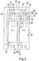
- FIG. 2 Schematically, this is in Fig. 2 shown.
- a current transformer module 10 according to the invention is arranged lying close to an actuator assembly 32 per channel.
- conductor tracks that run on the underside of the board 30, dashed lines drawn.
- a first conductor 36 connects a first connection terminal 34 'to a first connection pin of the actuator assembly 32.
- a second conductor 36' connects a second connection terminal 34 "to the first primary-side connection 26 of the current transformer module 10, and to the second primary-side connection 26 'of the current transformer module 10 From the outlet openings 25, 25 'of the housing of the current transformer module 10 lead the two insulated leads 19, 19' past the actuator assembly to the bus terminal side 35 of the board 30, where the plug 207 is received in a receptacle for the purpose of electrical connection.
- the switch actuator assembly 32 has a galvanic isolation between its load and her bus side. By removing the secondary-side connections of the toroidal coil of the current transformer module 10 by means of the insulated connection wires 19, 19 'on the bus side of the board, the potential separation on the circuit board 30 is ensured.
- the first, primary-side connection points 26, 26 'and the outlet openings 25, 25' for the secondary-side connection wires 19, 19 'in the longitudinal direction of the current transformer module are close to each other. Due to the internal structure of the current transformer module 10 described above, nevertheless, all prescribed clearances and creepage distances are maintained, and this with an overall very compact design of the current transformer module 10. This can be easily assembled as a prefabricated module on the board. You can also see in the Fig. 2 in that the current transformer module can be set very close to the actuator assembly 32 and to current transformers 10 'of adjacent channels.
Landscapes
- Engineering & Computer Science (AREA)
- Power Engineering (AREA)
- Transformers For Measuring Instruments (AREA)
- Coils Or Transformers For Communication (AREA)
- Details Of Connecting Devices For Male And Female Coupling (AREA)
Claims (10)
- Module transformateur de courant (10) pour un appareil d'installation compatible bus, comportant un socle (20) dans lequel est disposé un enroulement de noyau annulaire (11) du module, formant un circuit secondaire du transformateur de courant et comportant des bornes (18, 18'), dans lequel un fil isolé (12) formant un circuit primaire du transformateur de courant est amené à passer à travers l'enroulement de noyau annulaire (11), dans lequel un emplacement d'entrée (16) de l'entrée du fil isolé (12) dans l'anneau de l'enroulement de noyau annulaire (11) et un emplacement de sortie de la sortie du fil isolé (12) de l'anneau de l'enroulement de noyau annulaire (11) sont fixés, et le fil isolé (12) est dénudé à ses extrémités de manière à former des extrémités libres (14), dans lequel le socle (20) est réalisé de manière à présenter la forme d'une écuelle et comporte une plaque inférieure (201), des côtés larges (202) et des côtés étroits (203, 203'), et le fil isolé (12) formant le circuit primaire fait partie du module transformateur de courant (10) et est amené à passer d'une première extrémité libre (14) jusqu'à l'emplacement d'entrée (16) sur un premier côté large (202) de la paroi extérieure (22) du socle (20) et de l'emplacement de sortie vers une deuxième extrémité libre sur un deuxième côté large opposé de la paroi extérieure (22) du socle (20),
caractérisé en ce que les bornes (18, 18') de l'enrouement de noyau annulaire (11) sont écartées du socle (20) par l'intermédiaire d'un fil de raccordement (19, 19') de manière à ce que les fils de raccordement (19, 19') puissent être reliés à une carte (30) en étant éloignés du socle (20) et en ce que les fils de raccordement (19, 19') font partie du module transformateur de courant (10). - Module transformateur de courant (10) selon la revendication 1, caractérisé en ce que le fil isolé (12) formant le circuit primaire est réalisé sous la forme d'un fil double, comprenant deux fils individuels isolés (13, 13') disposés côte à côte.
- Module transformateur de courant (10) selon la revendication 2, caractérisé en ce que les fils individuels (13, 13') sont munis d'un revêtement d'isolation à trois couches.
- Module transformateur de courant (10) selon la revendication 1, caractérisé en ce que l'enroulement de noyau annulaire (11) comporte au moins 1000 enroulements.
- Module transformateur de courant (10) selon la revendication 1, caractérisé en ce que l'enroulement de noyau annulaire (11) est entouré d'une bande de feuille en tant qu'isolation supplémentaire.
- Module transformateur de courant (10) selon la revendication 1, caractérisé en ce que le module transformateur de courant (10) comprend un boîtier (24) sous forme de structure de socle, constitué du socle (20) et d'un couvercle (21) qui comporte une plaque de recouvrement (204) opposée à la plaque inférieure (201) du socle (20).
- Module transformateur de courant (10) selon la revendication 1, caractérisé en ce que la première extrémité libre (14) du fil isolé (12), au niveau d'un premier point de raccordement (26), et la deuxième extrémité libre du fil isolé (12), au niveau d'un deuxième point de raccordement dépassent de la plaque inférieure (201) du socle (20), dans lequel les deux points de raccordement (26) sont situés à proximité d'un premier côté étroit (203) du socle (20).
- Module transformateur de courant (10) selon la revendication 7, caractérisé en ce que des barrettes de raccordement (23, 23') sont formées sur le socle (20), lesquelles barrettes portent les bornes (18, 18') de l'enroulement de noyau annulaire (11), dans lequel les barrettes de raccordement (23, 23') sont disposées à proximité d'un deuxième côté étroit (203') du socle (20), qui est opposé au premier côté étroit (203).
- Module transformateur de courant (10) selon la revendication 8, caractérisé en ce que le fil de raccordement isolant (19, 19') sort du boîtier (24) au niveau d'une ouverture de sortie (25, 25'), dans lequel l'ouverture de sortie (25, 25') est réalisée dans le couvercle (21) en face du premier ou du deuxième point de raccordement (26).
- Appareil d'installation compatible bus, notamment actionneur de commutation, comportant une carte (30) sur laquelle sont montés un module transformateur de courant (10) selon l'une des revendications précédentes et un ensemble actionneur (32), caractérisé en ce que le module transformateur de courant (10) est disposé au voisinage de l'ensemble actionneur (32) et en ce que les extrémités libres (14) sont reliées électriquement à l'emplacement de fixation du transformateur de courant (10) sur la carte (30), et en ce que le fil de raccordement (19, 19') est relié électriquement à la carte (30), au niveau d'un côté de l'ensemble actionneur (32) qui est opposé au module transformateur de courant (10) et en ce que le module transformateur de courant (10) et l'ensemble actionneur (32) font partie de l'appareil d'installation.
Applications Claiming Priority (1)
| Application Number | Priority Date | Filing Date | Title |
|---|---|---|---|
| DE102010015488A DE102010015488A1 (de) | 2010-04-16 | 2010-04-16 | Stromwandlermodul für ein busfähiges Installationsgerät |
Publications (3)
| Publication Number | Publication Date |
|---|---|
| EP2378528A2 EP2378528A2 (fr) | 2011-10-19 |
| EP2378528A3 EP2378528A3 (fr) | 2017-07-26 |
| EP2378528B1 true EP2378528B1 (fr) | 2018-10-24 |
Family
ID=44260902
Family Applications (1)
| Application Number | Title | Priority Date | Filing Date |
|---|---|---|---|
| EP11002444.5A Active EP2378528B1 (fr) | 2010-04-16 | 2011-03-24 | Module transformateur de courant pour un appareil d'installation compatible bus |
Country Status (3)
| Country | Link |
|---|---|
| EP (1) | EP2378528B1 (fr) |
| CN (2) | CN102222560A (fr) |
| DE (1) | DE102010015488A1 (fr) |
Families Citing this family (4)
| Publication number | Priority date | Publication date | Assignee | Title |
|---|---|---|---|---|
| DE102010015488A1 (de) * | 2010-04-16 | 2011-10-20 | Abb Ag | Stromwandlermodul für ein busfähiges Installationsgerät |
| CN105529169A (zh) * | 2015-12-01 | 2016-04-27 | 上海法腾电力科技有限公司 | 550电器柜背部接线的电流互感器 |
| CN106449021B (zh) * | 2016-10-14 | 2017-12-22 | 无锡市海升电子科技有限公司 | 一种拆装便捷稳定性高的耐用型电流互感器 |
| CN110911097B (zh) * | 2019-12-24 | 2025-02-28 | 安徽华能集团电器有限公司 | 一种便于更换的电压互感器组件 |
Family Cites Families (6)
| Publication number | Priority date | Publication date | Assignee | Title |
|---|---|---|---|---|
| US6753749B1 (en) * | 2003-06-05 | 2004-06-22 | Artesyn Technologies, Inc. | Toroidal transformer enclosure |
| CN2639896Y (zh) * | 2003-07-29 | 2004-09-08 | 台达电子工业股份有限公司 | 电流感应模块 |
| DE102004021835B4 (de) * | 2004-05-04 | 2006-05-11 | Tyco Electronics Amp Gmbh | Geräteklemme |
| DE102007037058B4 (de) * | 2007-08-03 | 2015-07-30 | Siemens Aktiengesellschaft | Stromwandlermodul für ein Energie- und/oder Leistungsmessgerät sowie Energie- und/oder Leistungsmessgerät mit Stromwandlermodul |
| DE102009048935A1 (de) | 2009-07-28 | 2011-02-10 | Abb Ag | Busfähiges Steuerungsgerät zur Steuerung mindestens eines Verbrauchers |
| DE102010015488A1 (de) * | 2010-04-16 | 2011-10-20 | Abb Ag | Stromwandlermodul für ein busfähiges Installationsgerät |
-
2010
- 2010-04-16 DE DE102010015488A patent/DE102010015488A1/de not_active Ceased
- 2010-05-31 CN CN2010102004333A patent/CN102222560A/zh active Pending
- 2010-05-31 CN CN2010202209964U patent/CN202206288U/zh not_active Expired - Lifetime
-
2011
- 2011-03-24 EP EP11002444.5A patent/EP2378528B1/fr active Active
Also Published As
| Publication number | Publication date |
|---|---|
| EP2378528A3 (fr) | 2017-07-26 |
| CN102222560A (zh) | 2011-10-19 |
| CN202206288U (zh) | 2012-04-25 |
| EP2378528A2 (fr) | 2011-10-19 |
| DE102010015488A1 (de) | 2011-10-20 |
Similar Documents
| Publication | Publication Date | Title |
|---|---|---|
| DE19519594C2 (de) | Transformator | |
| DE102007051419A1 (de) | NH-Sicherungslasttrenner mit Stromwandler | |
| EP1865331A2 (fr) | Appareil électrique/électronique | |
| EP2587513A1 (fr) | Commutateur d'installation doté d'une unité de capteur de courant | |
| EP2378528B1 (fr) | Module transformateur de courant pour un appareil d'installation compatible bus | |
| EP3340272B1 (fr) | Transformateurs sommateurs de courant adapté à tous les courants, disjoncteur de protection électromécanique et procédé de fabrication | |
| DE29913160U1 (de) | Isolierhülle für Transformator | |
| DE19712900A1 (de) | Sensoranordnung zur Strom- und Spannungsmessung | |
| DE69117403T2 (de) | Niederprofil-flachtransformator für die verwendung bei unabhängig betriebenen schaltnetzteilen | |
| DE69401800T2 (de) | Mehrzweckstromdurchführung | |
| DE69412149T2 (de) | Differentialschutzeinheit mit auf Funktion testbarer Untereinheit | |
| DE102009049489A1 (de) | Anschlussklemme und Elektroinstallationsgerät mit einer Anschlussklemme | |
| DE19506589C2 (de) | Elektrische Zündspule | |
| DE102012201002B4 (de) | Summenstromwandlergehäuse, Summenstromwandler und Fehlerstromschutzschalter | |
| DE102005007334B4 (de) | Summenstromwandler zur allstromsensitiven Erfassung eines elektrischen Differenzstromes | |
| DE102021132350A1 (de) | Niederspannungsstromwandler | |
| DE102007025421B4 (de) | Zündtransformator und Zündmodul | |
| EP3698148A1 (fr) | Transformateur de courant comprenant une isolation par fluide ou papier huilé pour haute tension | |
| DE60104027T2 (de) | Elektrischer Energiezähler | |
| WO2024231085A1 (fr) | Transducteur doté d'un capteur de tension flexible | |
| DE112006003946B4 (de) | Induktives Bauteil mit einem Spulenkörper mit integrierter Wicklung | |
| EP0279916B1 (fr) | Dispositif à bornes de connexion, en particulier pour des inductances ou des transformateurs | |
| DE102007037058B4 (de) | Stromwandlermodul für ein Energie- und/oder Leistungsmessgerät sowie Energie- und/oder Leistungsmessgerät mit Stromwandlermodul | |
| DE102005050318B3 (de) | Wandlereinheit und Vorrichtung zur allstromsensitiven Erfassung eines elektrischen Differenzstromes | |
| EP1693943A2 (fr) | Dispositif pour la détection des courants différentiels continus ou alternatifs |
Legal Events
| Date | Code | Title | Description |
|---|---|---|---|
| AK | Designated contracting states |
Kind code of ref document: A2 Designated state(s): AL AT BE BG CH CY CZ DE DK EE ES FI FR GB GR HR HU IE IS IT LI LT LU LV MC MK MT NL NO PL PT RO RS SE SI SK SM TR |
|
| AX | Request for extension of the european patent |
Extension state: BA ME |
|
| PUAI | Public reference made under article 153(3) epc to a published international application that has entered the european phase |
Free format text: ORIGINAL CODE: 0009012 |
|
| PUAL | Search report despatched |
Free format text: ORIGINAL CODE: 0009013 |
|
| AK | Designated contracting states |
Kind code of ref document: A3 Designated state(s): AL AT BE BG CH CY CZ DE DK EE ES FI FR GB GR HR HU IE IS IT LI LT LU LV MC MK MT NL NO PL PT RO RS SE SI SK SM TR |
|
| AX | Request for extension of the european patent |
Extension state: BA ME |
|
| RIC1 | Information provided on ipc code assigned before grant |
Ipc: H01F 27/32 20060101ALI20170619BHEP Ipc: H01F 38/30 20060101AFI20170619BHEP Ipc: H01F 27/26 20060101ALI20170619BHEP Ipc: H01F 27/30 20060101ALI20170619BHEP Ipc: G01R 15/18 20060101ALI20170619BHEP Ipc: H01F 27/02 20060101ALI20170619BHEP |
|
| STAA | Information on the status of an ep patent application or granted ep patent |
Free format text: STATUS: REQUEST FOR EXAMINATION WAS MADE |
|
| 17P | Request for examination filed |
Effective date: 20180118 |
|
| GRAP | Despatch of communication of intention to grant a patent |
Free format text: ORIGINAL CODE: EPIDOSNIGR1 |
|
| STAA | Information on the status of an ep patent application or granted ep patent |
Free format text: STATUS: GRANT OF PATENT IS INTENDED |
|
| INTG | Intention to grant announced |
Effective date: 20180608 |
|
| GRAS | Grant fee paid |
Free format text: ORIGINAL CODE: EPIDOSNIGR3 |
|
| GRAA | (expected) grant |
Free format text: ORIGINAL CODE: 0009210 |
|
| STAA | Information on the status of an ep patent application or granted ep patent |
Free format text: STATUS: THE PATENT HAS BEEN GRANTED |
|
| AK | Designated contracting states |
Kind code of ref document: B1 Designated state(s): AL AT BE BG CH CY CZ DE DK EE ES FI FR GB GR HR HU IE IS IT LI LT LU LV MC MK MT NL NO PL PT RO RS SE SI SK SM TR |
|
| REG | Reference to a national code |
Ref country code: GB Ref legal event code: FG4D Free format text: NOT ENGLISH |
|
| REG | Reference to a national code |
Ref country code: CH Ref legal event code: EP |
|
| REG | Reference to a national code |
Ref country code: IE Ref legal event code: FG4D Free format text: LANGUAGE OF EP DOCUMENT: GERMAN |
|
| REG | Reference to a national code |
Ref country code: AT Ref legal event code: REF Ref document number: 1057658 Country of ref document: AT Kind code of ref document: T Effective date: 20181115 |
|
| REG | Reference to a national code |
Ref country code: DE Ref legal event code: R096 Ref document number: 502011014887 Country of ref document: DE |
|
| REG | Reference to a national code |
Ref country code: NL Ref legal event code: FP |
|
| REG | Reference to a national code |
Ref country code: LT Ref legal event code: MG4D |
|
| PG25 | Lapsed in a contracting state [announced via postgrant information from national office to epo] |
Ref country code: IS Free format text: LAPSE BECAUSE OF FAILURE TO SUBMIT A TRANSLATION OF THE DESCRIPTION OR TO PAY THE FEE WITHIN THE PRESCRIBED TIME-LIMIT Effective date: 20190224 Ref country code: BG Free format text: LAPSE BECAUSE OF FAILURE TO SUBMIT A TRANSLATION OF THE DESCRIPTION OR TO PAY THE FEE WITHIN THE PRESCRIBED TIME-LIMIT Effective date: 20190124 Ref country code: FI Free format text: LAPSE BECAUSE OF FAILURE TO SUBMIT A TRANSLATION OF THE DESCRIPTION OR TO PAY THE FEE WITHIN THE PRESCRIBED TIME-LIMIT Effective date: 20181024 Ref country code: ES Free format text: LAPSE BECAUSE OF FAILURE TO SUBMIT A TRANSLATION OF THE DESCRIPTION OR TO PAY THE FEE WITHIN THE PRESCRIBED TIME-LIMIT Effective date: 20181024 Ref country code: LV Free format text: LAPSE BECAUSE OF FAILURE TO SUBMIT A TRANSLATION OF THE DESCRIPTION OR TO PAY THE FEE WITHIN THE PRESCRIBED TIME-LIMIT Effective date: 20181024 Ref country code: HR Free format text: LAPSE BECAUSE OF FAILURE TO SUBMIT A TRANSLATION OF THE DESCRIPTION OR TO PAY THE FEE WITHIN THE PRESCRIBED TIME-LIMIT Effective date: 20181024 Ref country code: LT Free format text: LAPSE BECAUSE OF FAILURE TO SUBMIT A TRANSLATION OF THE DESCRIPTION OR TO PAY THE FEE WITHIN THE PRESCRIBED TIME-LIMIT Effective date: 20181024 Ref country code: PL Free format text: LAPSE BECAUSE OF FAILURE TO SUBMIT A TRANSLATION OF THE DESCRIPTION OR TO PAY THE FEE WITHIN THE PRESCRIBED TIME-LIMIT Effective date: 20181024 Ref country code: NO Free format text: LAPSE BECAUSE OF FAILURE TO SUBMIT A TRANSLATION OF THE DESCRIPTION OR TO PAY THE FEE WITHIN THE PRESCRIBED TIME-LIMIT Effective date: 20190124 |
|
| PG25 | Lapsed in a contracting state [announced via postgrant information from national office to epo] |
Ref country code: PT Free format text: LAPSE BECAUSE OF FAILURE TO SUBMIT A TRANSLATION OF THE DESCRIPTION OR TO PAY THE FEE WITHIN THE PRESCRIBED TIME-LIMIT Effective date: 20190224 Ref country code: GR Free format text: LAPSE BECAUSE OF FAILURE TO SUBMIT A TRANSLATION OF THE DESCRIPTION OR TO PAY THE FEE WITHIN THE PRESCRIBED TIME-LIMIT Effective date: 20190125 Ref country code: RS Free format text: LAPSE BECAUSE OF FAILURE TO SUBMIT A TRANSLATION OF THE DESCRIPTION OR TO PAY THE FEE WITHIN THE PRESCRIBED TIME-LIMIT Effective date: 20181024 Ref country code: AL Free format text: LAPSE BECAUSE OF FAILURE TO SUBMIT A TRANSLATION OF THE DESCRIPTION OR TO PAY THE FEE WITHIN THE PRESCRIBED TIME-LIMIT Effective date: 20181024 Ref country code: SE Free format text: LAPSE BECAUSE OF FAILURE TO SUBMIT A TRANSLATION OF THE DESCRIPTION OR TO PAY THE FEE WITHIN THE PRESCRIBED TIME-LIMIT Effective date: 20181024 |
|
| REG | Reference to a national code |
Ref country code: DE Ref legal event code: R097 Ref document number: 502011014887 Country of ref document: DE |
|
| PG25 | Lapsed in a contracting state [announced via postgrant information from national office to epo] |
Ref country code: IT Free format text: LAPSE BECAUSE OF FAILURE TO SUBMIT A TRANSLATION OF THE DESCRIPTION OR TO PAY THE FEE WITHIN THE PRESCRIBED TIME-LIMIT Effective date: 20181024 Ref country code: CZ Free format text: LAPSE BECAUSE OF FAILURE TO SUBMIT A TRANSLATION OF THE DESCRIPTION OR TO PAY THE FEE WITHIN THE PRESCRIBED TIME-LIMIT Effective date: 20181024 Ref country code: DK Free format text: LAPSE BECAUSE OF FAILURE TO SUBMIT A TRANSLATION OF THE DESCRIPTION OR TO PAY THE FEE WITHIN THE PRESCRIBED TIME-LIMIT Effective date: 20181024 |
|
| PG25 | Lapsed in a contracting state [announced via postgrant information from national office to epo] |
Ref country code: EE Free format text: LAPSE BECAUSE OF FAILURE TO SUBMIT A TRANSLATION OF THE DESCRIPTION OR TO PAY THE FEE WITHIN THE PRESCRIBED TIME-LIMIT Effective date: 20181024 Ref country code: SM Free format text: LAPSE BECAUSE OF FAILURE TO SUBMIT A TRANSLATION OF THE DESCRIPTION OR TO PAY THE FEE WITHIN THE PRESCRIBED TIME-LIMIT Effective date: 20181024 Ref country code: RO Free format text: LAPSE BECAUSE OF FAILURE TO SUBMIT A TRANSLATION OF THE DESCRIPTION OR TO PAY THE FEE WITHIN THE PRESCRIBED TIME-LIMIT Effective date: 20181024 Ref country code: SK Free format text: LAPSE BECAUSE OF FAILURE TO SUBMIT A TRANSLATION OF THE DESCRIPTION OR TO PAY THE FEE WITHIN THE PRESCRIBED TIME-LIMIT Effective date: 20181024 |
|
| PLBE | No opposition filed within time limit |
Free format text: ORIGINAL CODE: 0009261 |
|
| STAA | Information on the status of an ep patent application or granted ep patent |
Free format text: STATUS: NO OPPOSITION FILED WITHIN TIME LIMIT |
|
| 26N | No opposition filed |
Effective date: 20190725 |
|
| PG25 | Lapsed in a contracting state [announced via postgrant information from national office to epo] |
Ref country code: MC Free format text: LAPSE BECAUSE OF FAILURE TO SUBMIT A TRANSLATION OF THE DESCRIPTION OR TO PAY THE FEE WITHIN THE PRESCRIBED TIME-LIMIT Effective date: 20181024 Ref country code: SI Free format text: LAPSE BECAUSE OF FAILURE TO SUBMIT A TRANSLATION OF THE DESCRIPTION OR TO PAY THE FEE WITHIN THE PRESCRIBED TIME-LIMIT Effective date: 20181024 |
|
| GBPC | Gb: european patent ceased through non-payment of renewal fee |
Effective date: 20190324 |
|
| PG25 | Lapsed in a contracting state [announced via postgrant information from national office to epo] |
Ref country code: LU Free format text: LAPSE BECAUSE OF NON-PAYMENT OF DUE FEES Effective date: 20190324 |
|
| REG | Reference to a national code |
Ref country code: BE Ref legal event code: MM Effective date: 20190331 |
|
| PG25 | Lapsed in a contracting state [announced via postgrant information from national office to epo] |
Ref country code: IE Free format text: LAPSE BECAUSE OF NON-PAYMENT OF DUE FEES Effective date: 20190324 Ref country code: GB Free format text: LAPSE BECAUSE OF NON-PAYMENT OF DUE FEES Effective date: 20190324 |
|
| PG25 | Lapsed in a contracting state [announced via postgrant information from national office to epo] |
Ref country code: BE Free format text: LAPSE BECAUSE OF NON-PAYMENT OF DUE FEES Effective date: 20190331 Ref country code: FR Free format text: LAPSE BECAUSE OF NON-PAYMENT OF DUE FEES Effective date: 20190331 |
|
| PG25 | Lapsed in a contracting state [announced via postgrant information from national office to epo] |
Ref country code: TR Free format text: LAPSE BECAUSE OF FAILURE TO SUBMIT A TRANSLATION OF THE DESCRIPTION OR TO PAY THE FEE WITHIN THE PRESCRIBED TIME-LIMIT Effective date: 20181024 |
|
| PG25 | Lapsed in a contracting state [announced via postgrant information from national office to epo] |
Ref country code: MT Free format text: LAPSE BECAUSE OF FAILURE TO SUBMIT A TRANSLATION OF THE DESCRIPTION OR TO PAY THE FEE WITHIN THE PRESCRIBED TIME-LIMIT Effective date: 20181024 |
|
| PG25 | Lapsed in a contracting state [announced via postgrant information from national office to epo] |
Ref country code: CY Free format text: LAPSE BECAUSE OF FAILURE TO SUBMIT A TRANSLATION OF THE DESCRIPTION OR TO PAY THE FEE WITHIN THE PRESCRIBED TIME-LIMIT Effective date: 20181024 |
|
| PG25 | Lapsed in a contracting state [announced via postgrant information from national office to epo] |
Ref country code: HU Free format text: LAPSE BECAUSE OF FAILURE TO SUBMIT A TRANSLATION OF THE DESCRIPTION OR TO PAY THE FEE WITHIN THE PRESCRIBED TIME-LIMIT; INVALID AB INITIO Effective date: 20110324 |
|
| PG25 | Lapsed in a contracting state [announced via postgrant information from national office to epo] |
Ref country code: MK Free format text: LAPSE BECAUSE OF FAILURE TO SUBMIT A TRANSLATION OF THE DESCRIPTION OR TO PAY THE FEE WITHIN THE PRESCRIBED TIME-LIMIT Effective date: 20181024 |
|
| PGFP | Annual fee paid to national office [announced via postgrant information from national office to epo] |
Ref country code: CH Payment date: 20250401 Year of fee payment: 15 |
|
| REG | Reference to a national code |
Ref country code: CH Ref legal event code: U11 Free format text: ST27 STATUS EVENT CODE: U-0-0-U10-U11 (AS PROVIDED BY THE NATIONAL OFFICE) Effective date: 20260401 |
|
| PGFP | Annual fee paid to national office [announced via postgrant information from national office to epo] |
Ref country code: DE Payment date: 20260319 Year of fee payment: 16 |
|
| PGFP | Annual fee paid to national office [announced via postgrant information from national office to epo] |
Ref country code: AT Payment date: 20260320 Year of fee payment: 16 |
|
| PGFP | Annual fee paid to national office [announced via postgrant information from national office to epo] |
Ref country code: NL Payment date: 20260319 Year of fee payment: 16 |