EP2378624A2 - Anschlussstruktur von Anschlussklemmen - Google Patents
Anschlussstruktur von Anschlussklemmen Download PDFInfo
- Publication number
- EP2378624A2 EP2378624A2 EP11162201A EP11162201A EP2378624A2 EP 2378624 A2 EP2378624 A2 EP 2378624A2 EP 11162201 A EP11162201 A EP 11162201A EP 11162201 A EP11162201 A EP 11162201A EP 2378624 A2 EP2378624 A2 EP 2378624A2
- Authority
- EP
- European Patent Office
- Prior art keywords
- terminal
- battery pack
- terminals
- electric apparatus
- male
- Prior art date
- Legal status (The legal status is an assumption and is not a legal conclusion. Google has not performed a legal analysis and makes no representation as to the accuracy of the status listed.)
- Granted
Links
Images




Classifications
-
- B—PERFORMING OPERATIONS; TRANSPORTING
- B25—HAND TOOLS; PORTABLE POWER-DRIVEN TOOLS; MANIPULATORS
- B25F—COMBINATION OR MULTI-PURPOSE TOOLS NOT OTHERWISE PROVIDED FOR; DETAILS OR COMPONENTS OF PORTABLE POWER-DRIVEN TOOLS NOT PARTICULARLY RELATED TO THE OPERATIONS PERFORMED AND NOT OTHERWISE PROVIDED FOR
- B25F5/00—Details or components of portable power-driven tools not particularly related to the operations performed and not otherwise provided for
-
- H—ELECTRICITY
- H01—ELECTRIC ELEMENTS
- H01M—PROCESSES OR MEANS, e.g. BATTERIES, FOR THE DIRECT CONVERSION OF CHEMICAL ENERGY INTO ELECTRICAL ENERGY
- H01M50/00—Constructional details or processes of manufacture of the non-active parts of electrochemical cells other than fuel cells, e.g. hybrid cells
- H01M50/20—Mountings; Secondary casings or frames; Racks, modules or packs; Suspension devices; Shock absorbers; Transport or carrying devices; Holders
- H01M50/244—Secondary casings; Racks; Suspension devices; Carrying devices; Holders characterised by their mounting method
-
- H—ELECTRICITY
- H01—ELECTRIC ELEMENTS
- H01M—PROCESSES OR MEANS, e.g. BATTERIES, FOR THE DIRECT CONVERSION OF CHEMICAL ENERGY INTO ELECTRICAL ENERGY
- H01M50/00—Constructional details or processes of manufacture of the non-active parts of electrochemical cells other than fuel cells, e.g. hybrid cells
- H01M50/20—Mountings; Secondary casings or frames; Racks, modules or packs; Suspension devices; Shock absorbers; Transport or carrying devices; Holders
- H01M50/247—Mountings; Secondary casings or frames; Racks, modules or packs; Suspension devices; Shock absorbers; Transport or carrying devices; Holders specially adapted for portable devices, e.g. mobile phones, computers, hand tools or pacemakers
-
- H—ELECTRICITY
- H01—ELECTRIC ELEMENTS
- H01M—PROCESSES OR MEANS, e.g. BATTERIES, FOR THE DIRECT CONVERSION OF CHEMICAL ENERGY INTO ELECTRICAL ENERGY
- H01M50/00—Constructional details or processes of manufacture of the non-active parts of electrochemical cells other than fuel cells, e.g. hybrid cells
- H01M50/20—Mountings; Secondary casings or frames; Racks, modules or packs; Suspension devices; Shock absorbers; Transport or carrying devices; Holders
- H01M50/296—Mountings; Secondary casings or frames; Racks, modules or packs; Suspension devices; Shock absorbers; Transport or carrying devices; Holders characterised by terminals of battery packs
-
- H—ELECTRICITY
- H01—ELECTRIC ELEMENTS
- H01R—ELECTRICALLY-CONDUCTIVE CONNECTIONS; STRUCTURAL ASSOCIATIONS OF A PLURALITY OF MUTUALLY-INSULATED ELECTRICAL CONNECTING ELEMENTS; COUPLING DEVICES; CURRENT COLLECTORS
- H01R13/00—Details of coupling devices of the kinds covered by groups H01R12/70 or H01R24/00 - H01R33/00
- H01R13/66—Structural association with built-in electrical component
- H01R13/70—Structural association with built-in electrical component with built-in switch
- H01R13/707—Structural association with built-in electrical component with built-in switch interlocked with contact members or counterpart
-
- Y—GENERAL TAGGING OF NEW TECHNOLOGICAL DEVELOPMENTS; GENERAL TAGGING OF CROSS-SECTIONAL TECHNOLOGIES SPANNING OVER SEVERAL SECTIONS OF THE IPC; TECHNICAL SUBJECTS COVERED BY FORMER USPC CROSS-REFERENCE ART COLLECTIONS [XRACs] AND DIGESTS
- Y02—TECHNOLOGIES OR APPLICATIONS FOR MITIGATION OR ADAPTATION AGAINST CLIMATE CHANGE
- Y02E—REDUCTION OF GREENHOUSE GAS [GHG] EMISSIONS, RELATED TO ENERGY GENERATION, TRANSMISSION OR DISTRIBUTION
- Y02E60/00—Enabling technologies; Technologies with a potential or indirect contribution to GHG emissions mitigation
- Y02E60/10—Energy storage using batteries
Definitions
- the present invention relates to a connecting terminal structure in which a tool battery (hereinafter termed “a battery pack”) and an electric apparatus are allowed to make a sliding movement relative to each other in a given direction, whereby the battery pack and the electric apparatus are connected with each other, and, further, terminals of the battery pack and those of the electric apparatus are electrically connected to each other.
- a battery pack a tool battery
- an electric apparatus are allowed to make a sliding movement relative to each other in a given direction
- Japanese Patent Application Laid-Open No. 2001-057204 Japanese Patent Application Laid-Open No. 2001-057204 discloses a relevant connecting terminal structure.
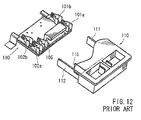
- a terminal portion of a battery pack 100 and a terminal portion of an electric power tool main body 110 are connected with each other.
- the terminal portion of the electric power tool main body 110 is provided with a negative male terminal 111 on the right end side and a positive male terminal 112 provided on the left end side, with a signal male terminal 115 provided between the terminals 111 and 112.
- the negative male terminal 111 and the positive male terminal 112 are formed in the form of a band plate extending in the direction in which the battery pack 100 slides, and the size of the terminals 111 and 112 are set to have an equal length.
- the signal male terminal 115 is formed in the form of a band plate parallel to the negative male terminal 111 and the positive male terminal 112, and is set to be shorter than the positive and negative male terminal 111 and 112.
- the terminal portion of the battery pack 100 is provided with a two-stage type negative female terminal 101a, 101b on the right end side, and a two-stage type positive female terminal 102a, 102b, And, a one-stage type signal female terminal 105 is provided between the negative female terminal 101a, 101b and the positive female terminal 102a, 102b, at a position corresponding to the signal male terminal 115 of the electric power tool main body 110.
- the battery pack 100 and the electric power tool main body 110 are allowed to make a relative sliding movement relative to each other, whereby the male terminals 111, 112, and 115 of the electric power tool main body 110 are respectively inserted into the female terminals 101a/101b, 102a/102b, and 105, thereby electrically connecting the terminals to each other.
- a connecting terminal structure in which a battery pack and an electric apparatus are allowed to make a sliding movement relative to each other in a given direction, whereby the battery pack and the electric apparatus are connected with each other, and, further, terminal of the battery pack and those of the electric apparatus are electrically connected to each other, wherein in one member of the battery pack and the electric apparatus, there are arranged in the sliding direction a plurality of terminals of different functions, and in the other member of the battery pack and the electric apparatus, there is provided at least one terminal to be connected to the terminal of the one member, and through relative sliding between the battery pack and the electric apparatus, a predetermined terminal on the other member reaches a predetermined corresponding terminal on the one member, and, in this process, the predetermined terminal on the other member can pass through another terminal on the one member.
- a predetermined terminal provided on the other member passes through another terminal on the one member.
- the other member of the battery pack and the electric apparatus is provided with a single terminal to be connected to one of the plurality of terminals of the one member, or is provided with a plurality of terminals arranged in the sliding direction that are to be respectively connected to the plurality of terminals.
- one of the plurality of terminals arranged in the sliding direction is a terminal for transmitting a battery pack identification signal.
- one of the plurality of terminals arranged in the sliding direction is a terminal for supplying charge current, and the other terminals are terminals for transmitting a discharge control signal.
- a terminal on the other member of the battery pack and the electric apparatus is a male terminal formed as a flat plate parallel to the sliding direction, with both ends in the sliding direction of the male terminal being beveled into a substantially wedge-like sectional configuration.
- both ends in the sliding direction of the male terminal formed as a flat plate are beveled into a substantially wedge-like sectional configuration so that the male terminal can be easily inserted and detached into and from the mating female terminal in the course of sliding.
- a terminal of one member of the battery pack and the electric apparatus is a female terminal forme so as to hold a male terminal of the other member from both sides, with the opening end portion dimension, of the female terminal being set larger than the width of a slit that guides a male terminal of the other member.
- the male terminal of the other member guided by the slit can be reliably inserted into the female terminal of the one member.
- the connecting terminal structure of the present embodiment includes a connecting terminal structure for a terminal portion of a battery pack and a terminal portion of an electric power tool main body, and a connecting terminal structure for a terminal portion of the battery pack and a terminal portion of a battery charger.
- front, rear, right, left, upper, and lower sides in the drawings correspond to the front, rear, right, left, upper, and lower sides of the electric power tool main body.
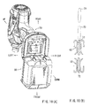
- a housing 11 of an electric power tool main body 10 includes a tubular housing main body portion 12 accommodating a motor M (See Fig. 1 ) etc. and a grip portion 15 formed so as to protrude from the lower portion of the housing main body portion 12. And, at an upper end portion (proximal end portion) of the grip portion 15, there is provided a trigger type switch lever 13. Further, at the lower end portion (distal end portion) of the grip portion 15, there is provided a battery connection portion 17 to which a battery pack 30 is connected.
- the battery connection portion 17 is configured to be connected to the battery pack 30 through a sliding movement from the rear to the front side with respect to the battery pack 30.
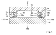
- the battery connection portion 17 of the electric power tool main body 10 is formed in the form of a substantially rectangular cap whose lower and front sides are open. And, as shown in Figs. 2A and 4 , at a right-hand and left-hand lower end portions of the battery connection portion 17, rail-like ridge portions 18 extending in the sliding direction (the longitudinal direction) of the battery pack 30 are formed so as to protrude inwardly in the width direction from the inner wall surface of the battery connection portion 17. And, as shown in Fig. 4 , above the right and left ridge portions 18, there are formed rectangular grooves 18m extending in the longitudinal direction along the ridge portions 18. As described below, lateral ridge portions 36t of slide rails 36 of the battery pack 30 are fit-engaged with the rectangular grooves 18m.
- a terminal portion 20 of the electric power tool main body 10 is provided at the central area on the back side of the battery connection portion 17.
- the terminals portion 20 is a member for fixing a positive male terminal 23p, a negative male terminal 23n, and a signal male terminal 23s at predetermined position on a lower end surface 17f of the battery connection portion 17.
- the terminal portion 20 is provided with a flat plate portion 21 fixed to the lower end surface 17f of the battery connection portion 17, and the positive male terminal 23p, the negative male terminal 23n, and the signal male terminal 23s are fixed to the lower surface of the flat plate portion 21 in an expose condition.
- the positive male terminal 23p and the negative male terminal 23n are formed in the form of a band plate so as to extend in the sliding direction of the battery pack 30 at the positions of the right and left ends of the flat plate portion 21, and both the terminals stand at substantially right angles with respect to the lower surface of the flat plate portion 21. Further, the positive male terminal 23p and the negative male terminal 23n have the same length.
- the signal male terminal 23s is formed in the form of a plate parallel to the negative male terminal 23n and the positive male terminal 23p, and is arranged at a predetermined position between the negative male terminal 23n and the positive male terminal 23p. As shown in Fig. 2B , both sides in the sliding direction of the signal male terminal 23s is beveled into a substantially wedge-like sectional configuration.
- the positive male terminal 23p of the terminal portion 20 of the electric power tool main body 10 is connected to the switch lever 13 for driving the motor M via a positive line P of the motor drive circuit, and the negative male terminal, 23n is connected to an FET for controlling the motor M via a negative line N of the motor drive circuit.
- the signal male terminal 23s is connected to an ON/OFF control terminal of the FET by a signal line S.
- the battery pack 30 is provided with an open-top case main body portion 32 accommodating a plurality of cells 31, and a cover portion 34 covering an opening 32h of the case main body portion 32.
- the case main body portion 32 and the cover portion 34 are formed substantially in a rectangular configuration, and the cover portion 34 is fastened to the case main body portion 32 by means of screws at a plurality of peripheral position.
- each of the right and left slide rails 36 includes a rail main body portion 36m and the lateral ridge portion 36t protruding outwardly in the width direction by a predetermined length from the upper side surface of the rail main body portion 36m.
- the right and left lateral ridge portions 36 can be fit-engaged with the right and left rectangular grooves 18m formed in the battery connection portion 17 of the electric power tool main body 10.
- stopper portions 36u are formed at the proximal end portions (front end portions) of the right and left slide rails 36.
- a left guide slit 37 In the front portion of the upper surface of the cover portion 34 of the battery pack 30, there are formed, between the right and left slide rails 36, a left guide slit 37, a right guide slit 38, and an intermediate guide slit 39, so as to be parallel to the slide rails 36.
- the positive male terminal 23p, the negative male terminal 23n, and the signal male terminal 23s of the electric power tool main body 10 can be inserted through the left guide slit 37, the right guide slit 38, and the intermediate guide slit 39, respectively.
- a positive female terminal 43 See Fig.
- the battery pack 30 On the inner side of the right guide slit 38, there is arranged a negative female terminal 44 of the battery pack 30. Further, on the inner side of the intermediate guide slit 39, there are arranged a charge female terminal 45 and a discharge control female terminal 46 side by side in the sliding direction. That is, the charge female terminal 45 is arranged on the rear end side (inlet side) of the intermediate guide slit 39, and the discharge control female terminal 46 is arranged on the front side of the charge female terminal 45 (i.e., on the depth side of the intermediate guide slit 39),
- a positive female terminal 43, a negative female terminal 44, a charge female terminal 45, and a discharge control female terminal 46 are fixed to a terminal portion 40 of the battery pack 30,
- the terminal portion 40 is a member for arranging the female terminals 43, 44, 45, and 46 at predetermined positions on the inner side of the cover portion 34.
- the terminal portion 40 is provided with a flat plate portion 41, on the upper surface of which the positive female terminal 43, the negative female terminal 44, the charge female terminal 45, and the discharge control female terminal 46 are arranged.
- the positive female terminal 43 and the negative female terminal 44 have the same configuration, and both the terminals can pinch the positive male terminal 23p and the negative male terminal 23n of the electric power tool main body 10 from both sides in the thickness direction, thereby connected to the male terminals 23p and 23n.
- the positive terminal 43 is provided with a first pinching portion 43a and a second pinching portion 43b arranged in the sliding direction, and the first pinching portion 43a and the second pinching portion 43b are conductors in the form of a plate spring.
- the first pinching portion 43a and the second pinching portion 43b are maintained in a state in which they electrically conductive with each other.
- the positive male terminal 23p of the electric power tool main body 10 is guided by the left guide slit 37 of the battery pack 30 to be inserted into the first pinching portion 43a and the second pinching portion 43b of the positive female terminal 43, whereby the positive male terminal 23p of the electric power tool main body 10 and the positive female terminal 43 of the battery pack 30 are electrically connected to each other.
- the positive female terminal 43 of the battery pack 30 is connected to positive electrodes of the cells 31 via the positive line P.
- the negative female terminal 44 is connected to negative electrodes of the cells 31 via the negative lina N.
- the charge female terminals 45 of the battery pack 30 is a terminal to which a positive male terminal 55 of a battery charger 50 described below is connected, and is connected to the positive electrodes of the cells 31 via a circuit switch portion 47 and the positive line P.
- the discharge control female terminal 46 of the battery pack 30 is a terminal to which the signal male terminal 23s of the electric power tool main body 10 is connected. It is connected to a discharge control output terminal of a CPU via the signal line S. Thugs, when, for example, a discharge stop signal is output from the discharge control output terminal of the CPU at the time of overdischarge of the battery pack 30, the FET of the electric power tool main body 10 turns off to stop the motor M.
- the charge female terminal 45 and the discharge control female terminals 46 have the same configuration, and, are provided symmetrically with respect to the sliding direction (the longitudinal direction), as shown in Fig. 6 .
- the discharge control female terminal 46 includes a left terminal piece 46a and a right terminal piece 46b that pinch the signal male terminal 23s of the electric power tool main body 10 from both sides in the thickness direction (lateral direction).
- the left terminal piece 46a and the right terminal piece 46b are conductors in the form of a spring plate.
- the distance between the left terminal piece 46a and the right terminal piece 46b is large on the front end side and the rear end side, and minimum at a halfway position 46c near the rear end.
- the signal male terminal 23s of the electric power tool main body 10 is configures to be pinched at the halfway position 46c and in the vicinity thereof.
- the distance dimension between the front end side and the rear end side of the discharge control female terminal 46 is set larger than the slit width of the intermediate guide slit 39.
- the charge female terminal 45 is of the same construction as the discharge control female terminal 46. As shown in Fig. 6C , the signal male terminal 23s of the electric power tool main body 10 can slideably pass between the left terminal end 45a and the right terminal end 45b, Thus, in the course of sliding, the signal male terminal, 23s of the electric power tool main body 10 is guided by the intermediate guide slit 39 to pass the charge female terminal 45, and is then guided to the position of the discharge control female terminal 46.
- both ends in the sliding direction of the signal male terminal 23s of the electric power tool main body 10 are beveled into a wedge-like sectional configuration, so that, at the time of insertion, the signal terminal can smoothly pass the charge female terminal 45 to be inserted into the discharge control female terminal 46. Also when pulling the signal male terminal 23s of the electric power tool main body 10 out of the discharge control female terminal 46, it can smoothly pass the charge female terminal 45.
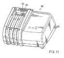
- a battery charger 50 has a battery connection portion 52 provided on the left-hand side of a housing 51.
- the battery connection portion 52 there are provided, on the right-hand and left-hand sides thereof, guide wall portions 56 extending in the longitudinal direction, and, at upper end positions of the opposing side walls of the right and left guide wall portions 56, there are formed ridge portions 56t in the form of a rail, which protrude inwardly in the width direction. That is, recesses 56m are formed under the ridge portions 56t. Further, the lateral ridge portions 36t of the battery pack 30 can be fit-engaged with the right and left recesses 56m, of the battery charger 50
- a negative male terminal 54 and a positive male terminal 55 between the right and left ridge portions 56t and at positions corresponding to the right guide slit 38 and the intermediate guide slit 39 of the battery pack 30.
- the negative male terminal 54 of the battery charger 50 has substantially the same configuration as the negative male terminal 23n of the electric power tool main body 10.
- the positive male terminal 55 of the battery charger 50 has substantially the same configuration as the signal male terminal 23s of the electric power tool main body 10, and is arranged at a position where it is connected to the charge female terminals 45 of the battery pack 30.
- the positive male terminal 55 of the battery charger 50 is connected to the positive terminal, of a DC power source 53 via the positive lines, and the negative male terminal 54 is connected to the negative terminal of the DC power source 53 via the negative line N.
- the front end portions of the rectangular grooves 18m provided in the battery connection portion 17 of the electric power tool main body 10 are fit-engaged with the lateral ridge portions 36t formed on the right and left slide rails 36 of the battery pack 30.
- the electric power tool main body 10 slides forwards with respect to the battery pack 30. As a result, the electric tool main body 10 and the battery pack 30 are connected with each other.
- the positive male terminal 23p, the negative male terminals 23n, and the signal male terminal 23s of the electric power tool main body 10 are inserted into the left guide slit 37, the right guide slit 38, and the intermediate guide slit 39 of the battery pack 30, respectively. Further, the positive male terminal 23p and the negative male terminal 23n are respectively guided by the left guide slit 37 and the right guide slit 38 of the battery pack 30 to be inserted into the positive female terminal 43 and the negative female terminal 44, Further, the signal male terminal 23s of the electric power tool main body 10 slidably passes through the charge female terminal 45 while guided by the intermediate guide slit 39 to be inserted into the discharge control female terminal 46.
- the connection of the electric power tool main body 10 and the battery pack 30 is complected.
- the positive male terminal 23p, the negative male terminal 23n, and the signal male terminal 23s of the electric power tool main body 10 are connected to the positive female terminal 43, the negative female terminal 44, and the discharge control female terminal 46 of the battery pack 30, respectively.
- the battery pack 30 When connecting the battery pack 30 to the battery charger 50, the battery pack 30 is held upside down, and in this state, the lateral ridge portions 36t formed on the right and left slide rails 36 of the battery pack 30 are fit-engaged with the right and left recesses 56m of the battery charger 50 from the front side Next, with the fit-engaged state maintained, the battery pack 30 slides backwards with respect to the battery charger 50, as can be seen in Fig. 7 . As a result, the battery pack 30 and the battery charger 50 are connected with each other.
- the negative male terminal 54 of the battery charger 50 is inserted into the right guide slit 38 of the battery pack 30, and the positive male terminal 55 of the battery charger 50 is inserted into the intermediate guide slit 39 of the battery pack 30, Further, as shown in Fig. 1B , when a slide movement is completed, the negative male terminal 54 of the battery charger 50 is connected to the negative female terminal 44 of the battery pack, 30, and the positive male terminal 55 of the battery charger 50 is connected to the charge female terminal 45 of the battery pack 30.
- the battery pack 30 correspond to one member of the present invention
- the battery charger 50 and the electric power tool main body 10 correspond to the other member of the present invention.
- the connecting terminal structure it is possible to arrange a plurality of terminals having different functions (the charge female terminal 45 and the discharge control female terminal 46) in the sliding direction in the battery pack 30.
- the charge female terminal 45 and the discharge control female terminal 46 there is no need to increase the size of the battery pack 30 in a direction perpendicular to the sliding direction, or, the width direction. Accordingly, it is possible to increase the number of terminals without having to increase the width of the battery pack 30.
- the width of the battery pack 30 does not increase, the width of the battery connection portion of the electric power tool main body 10 and of the battery charger 50, to which the battery pack 30 is connected, does not increase, either.
- the signal male terminal 23s of the electric power tool main body 10 is formed in the form of a flat plate, which are parallel to the sliding direction, and both ends in the sliding direction of the male terminal are beveled into a substantially wedge-like sectional configuration.
- the signal male terminal 23s can be easily inserted into and pulled out of the charge female terminal 45 and the discharge control female terminal 46 of the battery pack 30.
- the present invention is not restricted to the above-described embodiment but allows modification without departing from the subject matter of the invention.
- the male terminals 23p and 23n are provided on the electric power tool main body 10 side
- the female terminals 43 and 44 are provided on the battery pack 30 side.
- the positive terminal 43 of the battery pack 30, which is a high voltage side terminal may be formed as a male terminal
- the positive terminal 23p of the electric power tool main body 10, which is a low voltage side terminal may be formed as a female terminal.
- the terminal which is for higher voltage and more subject to temperature rise, is formed as a male terminal in the form of a flat plate, whereby it is possible to obtain a superior heat dissipation property and to suppress an increase in the temperature of the terminal.
- the positive terminal has the same configuration as the negative terminal, but the negative terminal may be configured such that the negative terminal in the battery pack and the corresponding negative terminal in the electric power tool main body 10 are connected with each other before the positive terminals are connected, which can avoid an unnecessary electric spark which could occur in case the positive terminals are connected before the negative terminals are connected.
- the charge female terminal 45 and the discharge control female terminal 46 are arranged on the battery pack 30 side by side in the sliding direction, and the positive male terminal 55 of the battery charger 50 is connected to the charge female terminal 45, with the signal male terminal 23s of the electric power tool main body 10 being connected to the discharge control female terminal 46.
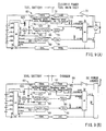
- a battery pack 60 provided with a temperature output female terminal 62 and a battery discrimination female terminal 63 may be arranged side by side in the sliding direction.
- the temperature output female terminal 62 is connected to a thermometer 62t detecting the cell temperature
- the battery discrimination female terminal 63 is connected to a resistor 63r showing a battery type.
- an electric power tool main body 70 to which the battery pack 60 is connected, is provided with a temperature input male terminal 72 and a battery discrimination female terminal 73, which correspond to the temperature output female terminal 62 and the battery discrimination female terminals 63 of the battery pack 30 and which are arranged side by side in the sliding direction.
- the temperature input male terminal 72 and the battery discrimination female terminal 73 of the electric power tool main body 70 are respectively connected to the temperature output female terminal 62 and the battery discrimination female terminal, 63 of the battery pack 60.
- a battery charger 80 to which the battery pack 60 is connected, is provided with a temperature input male terminal 82 and a battery discrimination female terminal 83 which correspond to the temperature output female terminal 62 and the battery discrimination female terminal 63 of the battery pack 30 and which are arranged side by side in the sliding direction. And, in the course of sliding, the temperature input male terminal 82 and the battery discrimination female terminal 83 of the battery charger 80 are respectively connected to the temperature output female terminal 62 and the battery discrimination female terminal 63 of the battery pack 60.
- a control voltage output female terminal 65 and the control voltage input female terminal 66 can be arranged side by side in the sliding direction.
- a control voltage input male terminals 75 of the electric power tool main body 70 is connected to the control voltage output female terminal 65
- a control voltage output male terminal 86 of the battery charger 80 is connected to the control voltage input female terminal 66.
- the overdischarge output female terminal 68 and the overcharge output female terminal 69 can be arranged side by side in the sliding direction.
- an overdischarge input male terminal 78 of the electric power tool main body 70 is connected to the overdischarge output female terminal 68
- an overcharge input male terminal 89 of the battery charger 80 is connected to the overcharge output female terminal 69.
- the predetermined male terminal in the course of connecting a predetermined male terminal to a predetermined female terminal, the predetermined male terminal passes through the female terminal while in contact with another female terminal.
- the electric power tool main body 10. 70 and the battery charger 50, 80 are used by way of example as the electric apparatus. It is also possible to use a battery checker etc. as the electric apparatus.
Landscapes
- General Chemical & Material Sciences (AREA)
- Chemical & Material Sciences (AREA)
- Chemical Kinetics & Catalysis (AREA)
- Electrochemistry (AREA)
- Engineering & Computer Science (AREA)
- Life Sciences & Earth Sciences (AREA)
- Mechanical Engineering (AREA)
- Biophysics (AREA)
- Computer Hardware Design (AREA)
- Battery Mounting, Suspending (AREA)
- Secondary Cells (AREA)
- Charge And Discharge Circuits For Batteries Or The Like (AREA)
- Portable Power Tools In General (AREA)
Applications Claiming Priority (1)
| Application Number | Priority Date | Filing Date | Title |
|---|---|---|---|
| JP2010092113A JP5523905B2 (ja) | 2010-04-13 | 2010-04-13 | 端子接続構造 |
Publications (3)
| Publication Number | Publication Date |
|---|---|
| EP2378624A2 true EP2378624A2 (de) | 2011-10-19 |
| EP2378624A3 EP2378624A3 (de) | 2013-11-20 |
| EP2378624B1 EP2378624B1 (de) | 2017-11-29 |
Family
ID=44501755
Family Applications (1)
| Application Number | Title | Priority Date | Filing Date |
|---|---|---|---|
| EP11162201.5A Active EP2378624B1 (de) | 2010-04-13 | 2011-04-13 | Anschlussstruktur von Anschlussklemmen |
Country Status (5)
| Country | Link |
|---|---|
| US (1) | US8282413B2 (de) |
| EP (1) | EP2378624B1 (de) |
| JP (1) | JP5523905B2 (de) |
| CN (1) | CN102222827B (de) |
| RU (1) | RU2543615C2 (de) |
Families Citing this family (18)
| Publication number | Priority date | Publication date | Assignee | Title |
|---|---|---|---|---|
| US9112292B2 (en) * | 2012-03-16 | 2015-08-18 | Makita Corporation | Terminal structure |
| JP5916514B2 (ja) * | 2012-05-24 | 2016-05-11 | リョービ株式会社 | 電池パック |
| KR20150006569A (ko) * | 2013-07-09 | 2015-01-19 | 주식회사 바이로봇 | 배터리 팩 |
| JP6408870B2 (ja) * | 2014-11-05 | 2018-10-17 | 株式会社マキタ | 電動工具 |
| JP6577229B2 (ja) | 2015-02-13 | 2019-09-18 | 株式会社マキタ | バッテリパック、及びバッテリシステム |
| US10348110B2 (en) | 2015-02-13 | 2019-07-09 | Makita Corporation | Battery pack |
| KR101715278B1 (ko) * | 2015-03-31 | 2017-03-13 | 계양전기 주식회사 | 전동공구용 배터리 |
| JP6480782B2 (ja) * | 2015-04-02 | 2019-03-13 | 株式会社マキタ | 電気機器 |
| CN106450071B (zh) * | 2015-08-04 | 2019-08-06 | 南京德朔实业有限公司 | 电池包及其与电动工具的组合和连接它们的方法 |
| RU2597203C1 (ru) * | 2015-08-24 | 2016-09-10 | Константин Дмитриевич Клочков | Устройство электропитания электронных приборов |
| DE102016120329A1 (de) * | 2016-10-25 | 2018-04-26 | Festool Gmbh | Anschlussvorrichtung eines Elektrogeräts oder eines Energiespeichers |
| FR3060872B1 (fr) * | 2016-12-15 | 2020-08-14 | Legrand France | Element de connexion electrique |
| EP3395505A1 (de) * | 2017-04-26 | 2018-10-31 | HILTI Aktiengesellschaft | Versetzte kontakte an einem akkumulator |
| EP3442080A1 (de) * | 2017-08-09 | 2019-02-13 | HILTI Aktiengesellschaft | Steckkupplung für eine akkueinheit |
| EP3444905A1 (de) * | 2017-08-18 | 2019-02-20 | HILTI Aktiengesellschaft | Steckkupplung für eine akkueinheit |
| JP7114448B2 (ja) * | 2018-11-30 | 2022-08-08 | 株式会社マキタ | 充電システム、バッテリパックおよび充電器 |
| US12300833B2 (en) | 2019-09-30 | 2025-05-13 | Makita Corporation | Battery pack |
| WO2021071655A1 (en) | 2019-10-11 | 2021-04-15 | Ariens Company | Power source and control system for a lawn mower |
Citations (2)
| Publication number | Priority date | Publication date | Assignee | Title |
|---|---|---|---|---|
| JP2001057204A (ja) | 1999-08-19 | 2001-02-27 | Makita Corp | 端子構造 |
| JP2010092113A (ja) | 2008-10-03 | 2010-04-22 | Fujitsu Microelectronics Ltd | 記憶装置、電子装置、および、データ管理方法 |
Family Cites Families (12)
| Publication number | Priority date | Publication date | Assignee | Title |
|---|---|---|---|---|
| NL8701180A (nl) * | 1987-05-15 | 1988-12-01 | Emerson Electric Co | Middenspanningsgereedschap. |
| US5814973A (en) * | 1996-09-20 | 1998-09-29 | Ericsson Inc. | Power unit and charger for a battery powered electrical apparatus and method |
| US6304058B2 (en) * | 1998-08-13 | 2001-10-16 | Black & Decker Inc. | Cordless power tool system |
| US6057608A (en) * | 1998-08-13 | 2000-05-02 | Black & Decker Inc. | Cordless power tool system |
| JP2001086656A (ja) * | 1999-07-09 | 2001-03-30 | Fujitsu Ltd | バッテリ監視装置 |
| JP3778262B2 (ja) * | 2000-12-21 | 2006-05-24 | 株式会社マキタ | 充電方式及び電池パック |
| EP1805863B1 (de) * | 2004-10-18 | 2013-06-26 | Black & Decker, Inc. | Schnurloses stromversorgungssystem |
| NL1027304C2 (nl) * | 2004-10-20 | 2006-04-24 | Mecal Applied Mechanics B V | Ondersteuningsconstructie, fixatieorgaan en werkwijze. |
| JP4997619B2 (ja) * | 2005-03-09 | 2012-08-08 | サムコ株式会社 | 誘導結合型プラズマ処理装置 |
| JP4333715B2 (ja) * | 2006-09-07 | 2009-09-16 | 日立工機株式会社 | 電池パック、充電器、及び電動工具 |
| JP2008305496A (ja) * | 2007-06-08 | 2008-12-18 | Victor Co Of Japan Ltd | プラグ接続切替装置及びプラグ接続切替方法 |
| CN101758488B (zh) * | 2008-10-30 | 2012-07-04 | 苏州宝时得电动工具有限公司 | 电动工具以及电动工具和电池包的组合 |
-
2010
- 2010-04-13 JP JP2010092113A patent/JP5523905B2/ja active Active
-
2011
- 2011-01-28 CN CN2011100348904A patent/CN102222827B/zh active Active
- 2011-04-08 US US13/082,989 patent/US8282413B2/en active Active
- 2011-04-12 RU RU2011114298/07A patent/RU2543615C2/ru active
- 2011-04-13 EP EP11162201.5A patent/EP2378624B1/de active Active
Patent Citations (3)
| Publication number | Priority date | Publication date | Assignee | Title |
|---|---|---|---|---|
| JP2001057204A (ja) | 1999-08-19 | 2001-02-27 | Makita Corp | 端子構造 |
| JP3698296B2 (ja) | 1999-08-19 | 2005-09-21 | 株式会社マキタ | 端子構造 |
| JP2010092113A (ja) | 2008-10-03 | 2010-04-22 | Fujitsu Microelectronics Ltd | 記憶装置、電子装置、および、データ管理方法 |
Also Published As
| Publication number | Publication date |
|---|---|
| US20110250780A1 (en) | 2011-10-13 |
| CN102222827B (zh) | 2013-10-02 |
| RU2543615C2 (ru) | 2015-03-10 |
| JP2011218514A (ja) | 2011-11-04 |
| CN102222827A (zh) | 2011-10-19 |
| US8282413B2 (en) | 2012-10-09 |
| JP5523905B2 (ja) | 2014-06-18 |
| EP2378624A3 (de) | 2013-11-20 |
| EP2378624B1 (de) | 2017-11-29 |
| RU2011114298A (ru) | 2012-10-20 |
Similar Documents
| Publication | Publication Date | Title |
|---|---|---|
| EP2378624B1 (de) | Anschlussstruktur von Anschlussklemmen | |
| JP7189297B2 (ja) | バッテリパック、電動工具、及び電動工具セット | |
| JP7383782B2 (ja) | バッテリパック | |
| EP3288147B1 (de) | Elektrisches werkzeug und steuerungsverfahren dafür | |
| US20140306660A1 (en) | Charging system | |
| US10559804B2 (en) | Battery pack | |
| CN104969408B (zh) | 电池包及电气设备 | |
| JP2006326765A (ja) | 電動工具 | |
| CN107534108A (zh) | 电池配线模块 | |
| EP3772393A1 (de) | Batteriepack | |
| US20160211685A1 (en) | Relay connector and battery pack | |
| CN109155211A (zh) | 采用机电触点和电力电子装置的混合mccb | |
| WO2007033695A1 (de) | Akkupack und elektrohandwerkzeuggerät | |
| EP4080674B1 (de) | Batteriemodul | |
| JP2014038720A (ja) | 電池パック | |
| WO2020066905A1 (ja) | 電池パック、電気機器及び電気機器システム | |
| CN115513610B (zh) | 电池包和包括电池包的车辆 | |
| EP3151343B1 (de) | Elektrischer verbinder und verfahren zum elektrischen kontaktieren eines ersten und zweiten anschlusses einer ersten und einer zweiten elektrischen zelle | |
| US20260081292A1 (en) | Battery pack | |
| US7056619B2 (en) | Chargeable battery for medical diagnostic instruments | |
| US20260081445A1 (en) | Battery charger | |
| US20230275295A1 (en) | Electric device system and battery pack | |
| US6166520A (en) | Intercell bussing system for battery pack | |
| CN219892229U (zh) | 工具系统和电池包 | |
| JPH06140022A (ja) | 電池装置 |
Legal Events
| Date | Code | Title | Description |
|---|---|---|---|
| AK | Designated contracting states |
Kind code of ref document: A2 Designated state(s): AL AT BE BG CH CY CZ DE DK EE ES FI FR GB GR HR HU IE IS IT LI LT LU LV MC MK MT NL NO PL PT RO RS SE SI SK SM TR |
|
| AX | Request for extension of the european patent |
Extension state: BA ME |
|
| PUAI | Public reference made under article 153(3) epc to a published international application that has entered the european phase |
Free format text: ORIGINAL CODE: 0009012 |
|
| REG | Reference to a national code |
Ref country code: DE Ref legal event code: R079 Ref document number: 602011043719 Country of ref document: DE Free format text: PREVIOUS MAIN CLASS: H02J0007000000 Ipc: B25F0005000000 |
|
| PUAL | Search report despatched |
Free format text: ORIGINAL CODE: 0009013 |
|
| AK | Designated contracting states |
Kind code of ref document: A3 Designated state(s): AL AT BE BG CH CY CZ DE DK EE ES FI FR GB GR HR HU IE IS IT LI LT LU LV MC MK MT NL NO PL PT RO RS SE SI SK SM TR |
|
| AX | Request for extension of the european patent |
Extension state: BA ME |
|
| RIC1 | Information provided on ipc code assigned before grant |
Ipc: B25F 5/00 20060101AFI20131016BHEP Ipc: H01R 13/707 20060101ALI20131016BHEP Ipc: H01M 2/10 20060101ALI20131016BHEP |
|
| 17P | Request for examination filed |
Effective date: 20140516 |
|
| RBV | Designated contracting states (corrected) |
Designated state(s): AL AT BE BG CH CY CZ DE DK EE ES FI FR GB GR HR HU IE IS IT LI LT LU LV MC MK MT NL NO PL PT RO RS SE SI SK SM TR |
|
| GRAP | Despatch of communication of intention to grant a patent |
Free format text: ORIGINAL CODE: EPIDOSNIGR1 |
|
| INTG | Intention to grant announced |
Effective date: 20170627 |
|
| GRAS | Grant fee paid |
Free format text: ORIGINAL CODE: EPIDOSNIGR3 |
|
| GRAA | (expected) grant |
Free format text: ORIGINAL CODE: 0009210 |
|
| AK | Designated contracting states |
Kind code of ref document: B1 Designated state(s): AL AT BE BG CH CY CZ DE DK EE ES FI FR GB GR HR HU IE IS IT LI LT LU LV MC MK MT NL NO PL PT RO RS SE SI SK SM TR |
|
| REG | Reference to a national code |
Ref country code: CH Ref legal event code: EP |
|
| REG | Reference to a national code |
Ref country code: AT Ref legal event code: REF Ref document number: 949959 Country of ref document: AT Kind code of ref document: T Effective date: 20171215 |
|
| REG | Reference to a national code |
Ref country code: IE Ref legal event code: FG4D |
|
| REG | Reference to a national code |
Ref country code: DE Ref legal event code: R096 Ref document number: 602011043719 Country of ref document: DE |
|
| REG | Reference to a national code |
Ref country code: NL Ref legal event code: MP Effective date: 20171129 |
|
| REG | Reference to a national code |
Ref country code: LT Ref legal event code: MG4D |
|
| REG | Reference to a national code |
Ref country code: AT Ref legal event code: MK05 Ref document number: 949959 Country of ref document: AT Kind code of ref document: T Effective date: 20171129 |
|
| REG | Reference to a national code |
Ref country code: FR Ref legal event code: PLFP Year of fee payment: 8 |
|
| PG25 | Lapsed in a contracting state [announced via postgrant information from national office to epo] |
Ref country code: LT Free format text: LAPSE BECAUSE OF FAILURE TO SUBMIT A TRANSLATION OF THE DESCRIPTION OR TO PAY THE FEE WITHIN THE PRESCRIBED TIME-LIMIT Effective date: 20171129 Ref country code: ES Free format text: LAPSE BECAUSE OF FAILURE TO SUBMIT A TRANSLATION OF THE DESCRIPTION OR TO PAY THE FEE WITHIN THE PRESCRIBED TIME-LIMIT Effective date: 20171129 Ref country code: FI Free format text: LAPSE BECAUSE OF FAILURE TO SUBMIT A TRANSLATION OF THE DESCRIPTION OR TO PAY THE FEE WITHIN THE PRESCRIBED TIME-LIMIT Effective date: 20171129 Ref country code: NO Free format text: LAPSE BECAUSE OF FAILURE TO SUBMIT A TRANSLATION OF THE DESCRIPTION OR TO PAY THE FEE WITHIN THE PRESCRIBED TIME-LIMIT Effective date: 20180228 Ref country code: SE Free format text: LAPSE BECAUSE OF FAILURE TO SUBMIT A TRANSLATION OF THE DESCRIPTION OR TO PAY THE FEE WITHIN THE PRESCRIBED TIME-LIMIT Effective date: 20171129 |
|
| PG25 | Lapsed in a contracting state [announced via postgrant information from national office to epo] |
Ref country code: LV Free format text: LAPSE BECAUSE OF FAILURE TO SUBMIT A TRANSLATION OF THE DESCRIPTION OR TO PAY THE FEE WITHIN THE PRESCRIBED TIME-LIMIT Effective date: 20171129 Ref country code: GR Free format text: LAPSE BECAUSE OF FAILURE TO SUBMIT A TRANSLATION OF THE DESCRIPTION OR TO PAY THE FEE WITHIN THE PRESCRIBED TIME-LIMIT Effective date: 20180301 Ref country code: BG Free format text: LAPSE BECAUSE OF FAILURE TO SUBMIT A TRANSLATION OF THE DESCRIPTION OR TO PAY THE FEE WITHIN THE PRESCRIBED TIME-LIMIT Effective date: 20180228 Ref country code: AT Free format text: LAPSE BECAUSE OF FAILURE TO SUBMIT A TRANSLATION OF THE DESCRIPTION OR TO PAY THE FEE WITHIN THE PRESCRIBED TIME-LIMIT Effective date: 20171129 Ref country code: HR Free format text: LAPSE BECAUSE OF FAILURE TO SUBMIT A TRANSLATION OF THE DESCRIPTION OR TO PAY THE FEE WITHIN THE PRESCRIBED TIME-LIMIT Effective date: 20171129 Ref country code: RS Free format text: LAPSE BECAUSE OF FAILURE TO SUBMIT A TRANSLATION OF THE DESCRIPTION OR TO PAY THE FEE WITHIN THE PRESCRIBED TIME-LIMIT Effective date: 20171129 |
|
| PG25 | Lapsed in a contracting state [announced via postgrant information from national office to epo] |
Ref country code: NL Free format text: LAPSE BECAUSE OF FAILURE TO SUBMIT A TRANSLATION OF THE DESCRIPTION OR TO PAY THE FEE WITHIN THE PRESCRIBED TIME-LIMIT Effective date: 20171129 |
|
| PG25 | Lapsed in a contracting state [announced via postgrant information from national office to epo] |
Ref country code: CY Free format text: LAPSE BECAUSE OF FAILURE TO SUBMIT A TRANSLATION OF THE DESCRIPTION OR TO PAY THE FEE WITHIN THE PRESCRIBED TIME-LIMIT Effective date: 20171129 Ref country code: EE Free format text: LAPSE BECAUSE OF FAILURE TO SUBMIT A TRANSLATION OF THE DESCRIPTION OR TO PAY THE FEE WITHIN THE PRESCRIBED TIME-LIMIT Effective date: 20171129 Ref country code: DK Free format text: LAPSE BECAUSE OF FAILURE TO SUBMIT A TRANSLATION OF THE DESCRIPTION OR TO PAY THE FEE WITHIN THE PRESCRIBED TIME-LIMIT Effective date: 20171129 Ref country code: SK Free format text: LAPSE BECAUSE OF FAILURE TO SUBMIT A TRANSLATION OF THE DESCRIPTION OR TO PAY THE FEE WITHIN THE PRESCRIBED TIME-LIMIT Effective date: 20171129 Ref country code: CZ Free format text: LAPSE BECAUSE OF FAILURE TO SUBMIT A TRANSLATION OF THE DESCRIPTION OR TO PAY THE FEE WITHIN THE PRESCRIBED TIME-LIMIT Effective date: 20171129 |
|
| REG | Reference to a national code |
Ref country code: DE Ref legal event code: R097 Ref document number: 602011043719 Country of ref document: DE |
|
| PG25 | Lapsed in a contracting state [announced via postgrant information from national office to epo] |
Ref country code: IT Free format text: LAPSE BECAUSE OF FAILURE TO SUBMIT A TRANSLATION OF THE DESCRIPTION OR TO PAY THE FEE WITHIN THE PRESCRIBED TIME-LIMIT Effective date: 20171129 Ref country code: SM Free format text: LAPSE BECAUSE OF FAILURE TO SUBMIT A TRANSLATION OF THE DESCRIPTION OR TO PAY THE FEE WITHIN THE PRESCRIBED TIME-LIMIT Effective date: 20171129 Ref country code: RO Free format text: LAPSE BECAUSE OF FAILURE TO SUBMIT A TRANSLATION OF THE DESCRIPTION OR TO PAY THE FEE WITHIN THE PRESCRIBED TIME-LIMIT Effective date: 20171129 Ref country code: PL Free format text: LAPSE BECAUSE OF FAILURE TO SUBMIT A TRANSLATION OF THE DESCRIPTION OR TO PAY THE FEE WITHIN THE PRESCRIBED TIME-LIMIT Effective date: 20171129 |
|
| PLBE | No opposition filed within time limit |
Free format text: ORIGINAL CODE: 0009261 |
|
| STAA | Information on the status of an ep patent application or granted ep patent |
Free format text: STATUS: NO OPPOSITION FILED WITHIN TIME LIMIT |
|
| 26N | No opposition filed |
Effective date: 20180830 |
|
| PG25 | Lapsed in a contracting state [announced via postgrant information from national office to epo] |
Ref country code: MC Free format text: LAPSE BECAUSE OF FAILURE TO SUBMIT A TRANSLATION OF THE DESCRIPTION OR TO PAY THE FEE WITHIN THE PRESCRIBED TIME-LIMIT Effective date: 20171129 Ref country code: SI Free format text: LAPSE BECAUSE OF FAILURE TO SUBMIT A TRANSLATION OF THE DESCRIPTION OR TO PAY THE FEE WITHIN THE PRESCRIBED TIME-LIMIT Effective date: 20171129 |
|
| REG | Reference to a national code |
Ref country code: CH Ref legal event code: PL |
|
| REG | Reference to a national code |
Ref country code: BE Ref legal event code: MM Effective date: 20180430 |
|
| REG | Reference to a national code |
Ref country code: IE Ref legal event code: MM4A |
|
| PG25 | Lapsed in a contracting state [announced via postgrant information from national office to epo] |
Ref country code: LU Free format text: LAPSE BECAUSE OF NON-PAYMENT OF DUE FEES Effective date: 20180413 |
|
| PG25 | Lapsed in a contracting state [announced via postgrant information from national office to epo] |
Ref country code: CH Free format text: LAPSE BECAUSE OF NON-PAYMENT OF DUE FEES Effective date: 20180430 Ref country code: LI Free format text: LAPSE BECAUSE OF NON-PAYMENT OF DUE FEES Effective date: 20180430 Ref country code: BE Free format text: LAPSE BECAUSE OF NON-PAYMENT OF DUE FEES Effective date: 20180430 |
|
| PG25 | Lapsed in a contracting state [announced via postgrant information from national office to epo] |
Ref country code: IE Free format text: LAPSE BECAUSE OF NON-PAYMENT OF DUE FEES Effective date: 20180413 |
|
| PG25 | Lapsed in a contracting state [announced via postgrant information from national office to epo] |
Ref country code: MT Free format text: LAPSE BECAUSE OF NON-PAYMENT OF DUE FEES Effective date: 20180413 |
|
| PG25 | Lapsed in a contracting state [announced via postgrant information from national office to epo] |
Ref country code: TR Free format text: LAPSE BECAUSE OF FAILURE TO SUBMIT A TRANSLATION OF THE DESCRIPTION OR TO PAY THE FEE WITHIN THE PRESCRIBED TIME-LIMIT Effective date: 20171129 |
|
| PG25 | Lapsed in a contracting state [announced via postgrant information from national office to epo] |
Ref country code: HU Free format text: LAPSE BECAUSE OF FAILURE TO SUBMIT A TRANSLATION OF THE DESCRIPTION OR TO PAY THE FEE WITHIN THE PRESCRIBED TIME-LIMIT; INVALID AB INITIO Effective date: 20110413 Ref country code: PT Free format text: LAPSE BECAUSE OF FAILURE TO SUBMIT A TRANSLATION OF THE DESCRIPTION OR TO PAY THE FEE WITHIN THE PRESCRIBED TIME-LIMIT Effective date: 20171129 |
|
| PG25 | Lapsed in a contracting state [announced via postgrant information from national office to epo] |
Ref country code: MK Free format text: LAPSE BECAUSE OF NON-PAYMENT OF DUE FEES Effective date: 20171129 |
|
| PG25 | Lapsed in a contracting state [announced via postgrant information from national office to epo] |
Ref country code: AL Free format text: LAPSE BECAUSE OF FAILURE TO SUBMIT A TRANSLATION OF THE DESCRIPTION OR TO PAY THE FEE WITHIN THE PRESCRIBED TIME-LIMIT Effective date: 20171129 Ref country code: IS Free format text: LAPSE BECAUSE OF FAILURE TO SUBMIT A TRANSLATION OF THE DESCRIPTION OR TO PAY THE FEE WITHIN THE PRESCRIBED TIME-LIMIT Effective date: 20180329 |
|
| PGFP | Annual fee paid to national office [announced via postgrant information from national office to epo] |
Ref country code: DE Payment date: 20250305 Year of fee payment: 15 |
|
| PGFP | Annual fee paid to national office [announced via postgrant information from national office to epo] |
Ref country code: GB Payment date: 20260313 Year of fee payment: 16 |
|
| PGFP | Annual fee paid to national office [announced via postgrant information from national office to epo] |
Ref country code: FR Payment date: 20260309 Year of fee payment: 16 |