EP2378847A2 - Revêtement d'instrument dans des appareils de commande électroniques pour la suppression/le retardement du feu - Google Patents
Revêtement d'instrument dans des appareils de commande électroniques pour la suppression/le retardement du feu Download PDFInfo
- Publication number
- EP2378847A2 EP2378847A2 EP11162019A EP11162019A EP2378847A2 EP 2378847 A2 EP2378847 A2 EP 2378847A2 EP 11162019 A EP11162019 A EP 11162019A EP 11162019 A EP11162019 A EP 11162019A EP 2378847 A2 EP2378847 A2 EP 2378847A2
- Authority
- EP
- European Patent Office
- Prior art keywords
- electronic component
- housing part
- control unit
- porous
- unit housing
- Prior art date
- Legal status (The legal status is an assumption and is not a legal conclusion. Google has not performed a legal analysis and makes no representation as to the accuracy of the status listed.)
- Withdrawn
Links
Images

Classifications
-
- H—ELECTRICITY
- H05—ELECTRIC TECHNIQUES NOT OTHERWISE PROVIDED FOR
- H05K—PRINTED CIRCUITS; CASINGS OR CONSTRUCTIONAL DETAILS OF ELECTRIC APPARATUS; MANUFACTURE OF ASSEMBLAGES OF ELECTRICAL COMPONENTS
- H05K5/00—Casings, cabinets or drawers for electric apparatus
- H05K5/02—Details
- H05K5/0209—Thermal insulation, e.g. for fire protection or for fire containment or for high temperature environments
Definitions
- intumescent coating which inflate at elevated temperatures to a thermally stable, multi-cellular thermal insulating protective film.
- the heat shield housing includes an outer case, a heat shield liner, and a heat insulator in which the heat sensitive articles are partially or fully embedded and which has a solid-solid phase transition at a predetermined temperature when the heat shield case is exposed to high ambient temperatures.
- EP 2 061 126 A2 discloses a fire protection grommet for foreclosing wall or ceiling openings for cables, pipes or similar elements and has a housing open on both sides with a cable channel forming interior. In this cable channel there are at least two fire protection strips of intumescent fire protection material, the bulk of the interior of the housing substantially completely sealed in the cable direction at high heat.
- EP 2 096 346 A2 discloses a conduit feedthrough for passing conduits through a component having a circumferentially closed housing which has a housing Passing through space for the lines surrounds, wherein in the housing an insert of intumescent material and a first, membrane-like and provided with a passage point, sealing element made of an elastic material are provided.
- US Pat. No. 6,410,137 B1 discloses a fire retardant material for shielding electromagnetic interference.
- an electrically conductive layer is delimited on one or both sides by an intumescent, pressure-sensitive adhesive layer.
- DE 36 33 257 A1 discloses a metallized, textile fabric with a partial or full surface coating of an intumescent flexible material, in particular tissue for shielding electromagnetic radiation in the range of 1 MHz to 1000 GHz for objects, in particular electrical and electronic equipment and components, and rooms.
- US 6,548,753 B1 discloses a housing, especially for fire suppression, for electrical components.
- a perforated cover plate of a housing which serves for ventilation, coated with an intumescent material.
- this intumescent material expands to seal the perforations.
- a draft that would spread the fire continues to be prevented and it is prevented at the same time that oxygen reaches the fire site.
- US 6,549,422 B1 discloses a device for containing and suppressing fires in electronic systems, comprising a guide rail for, for example, printed circuit boards, with at least one intumescent paint-coated aperture. From a certain temperature of the intumescent paint expands, thereby close the openings of the aperture and the fire-causing circuit board is sealed airtight.
- US 6,130,381 also discloses an electronic component housing having a grid coated with an intumescent fire retardant paint. In the case of a fire and the associated elevated temperatures, this intumescent coating expands and the air supply is prevented.
- This type of paint coating is much easier to do than attaching an extra fire retardant coating.
- the coating is only partial and serves to locally suppress the air supply.
- the fire is not completely enclosed, so that still gets oxygen to the fire and the fire can be carried on. So at best there is only a delay in the spread of the fire, not an asphyxiation.
- the housings of electronic control units are increasingly made of thermoplastics. Due to the increased complexity and integration density of the power electronics with increasing media load the risk of a short circuit with consequent fire in the control unit increases. This internal combustion engine fire ignites the relatively easily combustible thermoplastic housing with possibly serious consequences.
- intumescent coatings are used for the fire protection of load-bearing parts (wood or jet carriers), which, applied as a varnish layer, increase to 10 times their initial strength under fire load and form a non-combustible layer. As a result, the wood and / or steel structures retain their strength and a collapse of the burning building is avoided or at least significantly delayed.
- Such intumescent coatings are usually elastic coating materials and serve as insulation materials in high temperature applications. They preferably consist of an elastic binder and an inorganic filler combination. When exposed to high temperatures, As they are produced, inter alia, by direct effects of flame and heat and hot gas flows, the high-melting fillers react with the binder of polymers and forms a coherent, porous and insulating protective layer that withstands high gas flows and thus, depending on the material, minutes. to provide hours of protection from fire.
- the formed protective layer Due to its porosity, the formed protective layer has a significantly lower thermal conductivity than the components to be protected surrounded by it.
- the incombustibility of the polymeric support matrix also prevents heat convection and fire propagation.
- a thermal fuse is used to switch off a circuit at excess temperature.
- Thermal fuses are housed close to or in the electronic components to be monitored and have an electrical connection, which is realized via a, melting at a defined temperature, metal. If a temperature TS is exceeded, the metal melts, a solder joint is opened, for example via a spring, and the power supply of the control unit is thereby prevented.
- circuit carriers for example populated printed circuit boards, in which a short circuit with fire sequence is possible, keep the fire in the circuit board and reduce the risk of ignition of the rest of the control unit.
- the small thickness of the protective film (order of magnitude micro to millimeter), which swells only when needed to its effective thickness and forms the porous and insulating layer.
- the dimensions of the electronic components or the control unit housing parts are thereby increased only insignificantly, which allows efficient assembly of bones and brings a weight saving.
- the used intumescent coating is also elastic and can follow stretching movements of the carrier material, which can prove advantageous both during assembly and during operation.
- the intumescent coatings used are characterized by adjustable mechanical properties, such as swelling thickness, tear strength, elasticity and stiffness, as well as the temperature at which the porous and insulating layer foams when exposed to flame and heat.
- FIG. 1 shows a coated with an Intumeszenzbe Anlagen unit housing part 4 when new.
- this intumescent coating 12 can also be effected by a casting process.
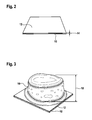
- FIG. 2 To illustrate the invention is in FIG. 2 by way of example a wood panel 10 with an intumescent coating 12 at room temperature with a layer thickness 14 shown.
- the layer thickness 14 in the initial state of the intumescent coating 12 is between 200 pm and 2 mm, wherein the composition of the intumescent coating 12 may be different from binder, inorganic fillers in powder form or short fibers, for example glass fiber reinforced plastic, and phosphoric acid ester for swelling the layer.
- the binders include PU (B), silicone rubbers (A), silicone resins, phenolic resins, melamine resins, epoxy resins, polyvinyl acetate, urea-aldehyde resin and / or polyurea resin.
- Inorganic fillers include silica, silicon carbide, titanium dioxide, sodium borate, zinc borate and / or sodium phosphate.
- FIG. 3 is the intumescent coating 12, wood panel 10 after 10 minutes of flaming through a round mask with a gas burner.
- the intumescent coating 12 of only a few millimeters thickness 14 is swelled to a layer, from now on called protective layer 16, with a thickness 18 of several centimeters.
- the intumescent coating 12 only swells up to its effective thickness 18 when needed.
- the dimensions of the coated electronic components or the control unit housing parts 4 are only insignificantly increased, which allows for an efficient mounting of control burrs and a weight saving compared to normally used non-combustible castings or fire-retardant paints with very high layer thicknesses.
- the used intumescent coating 12 is characterized by adjustable viscoelastic mechanical consistency with high tensile strength (between 1.5-10 N / mm 2 , at 20 ° C), good ductility (elongation at break between 10-80%, at 20 ° C), variable stiffness (elastic modulus between 5-100 N / mm 2 , at 20 ° C) and variable swelling thickness (30-120 times the starting layer thickness).
- adjustable viscoelastic mechanical consistency with high tensile strength (between 1.5-10 N / mm 2 , at 20 ° C), good ductility (elongation at break between 10-80%, at 20 ° C), variable stiffness (elastic modulus between 5-100 N / mm 2 , at 20 ° C) and variable swelling thickness (30-120 times the starting layer thickness).
- refractory fillers such as, for example, silicon carbide and silicon dioxide, react with a binder of polymers, which leads to a swelling of the intumescent coating 12 to approximately 30 to 120 times the original layer thickness 14.
- the protective layer 16 solidifies immediately after swelling with the fillers to a porous and insulating material.
- the intumescent coating 12 consumes only slowly. Therefore, by the swelling of the intumescent coating 12, a fire is effectively contained, so the Aufquellvorgang stops and the non-swollen part of the intumescent coating 12 is still available for fire prevention.
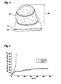
- a polyamide (PA6) plate 50 coated with an intumescent layer 12 is shown after 10 minutes of flaming through a round mask with a gas burner.
- the originally applied intumescent coating 12 is swollen after the action of heat on a protective layer 54 having the thickness 52.
- the fire for example, a circuit carrier or in a control unit, contained or at least delayed in order to reliably trigger the thermal fuse can.
- the formed protective layer 16 (FIG. FIG. 3 ) or 54 ( FIG. 4 ) possesses by its porosity a significantly lower thermal conductivity than the surrounded by it, to be protected components.
- the incombustibility of the polymeric support matrix also prevents heat convection and fire propagation.
- the resulting bulky protective layer 16 (FIG. FIG. 3 ) or 54 ( FIG. 4 ) also reduces the supply of atmospheric oxygen and thus acts branderstickend.
- FIG. 5 4 shows a diagram of a temperature profile on the back 56 of an uncoated or intumescent-coated polyamide (PA6) plate 50 (see FIG FIG. 4 ) during gas burner flame.
- PA6 intumescent-coated polyamide
- a material-identical polyamide (PA6) plate 50 is coated and flamed with an intumescent layer 12, the temperature rises only logarithmically to a plateau value. After 60 seconds, the temperature of the back 56 of the plate 50 is about 125 ° C and after 100 seconds about 150 ° C. Thereafter, the temperature rises only slightly and is also after 10 minutes at about 200 ° C. This temperature is below the flame point or softening point of the polyamide (PA6) plate 50. Inflammation of the polyamide (PA6) plate 50, as well as a rupture of the polyamide (PA6) plate 50, and thus a penetration of the flames, thus becomes effective prevented.
- Polyamides begin to decompose slowly at temperatures> 300 ° C. In the temperature range from 450 ° C to 500 ° C flammable gases are formed, which continue to burn after ignition. A control unit made of uncoated PA6 would therefore be completely useless after less than 100 seconds and a danger to surrounding components, while a controller with an intumescent enough time to trigger the internal thermal fuse and thus to protect the control unit and the surrounding components remains.
- the temperature TG at which the swelling of the intumescent coating occurs in the event of flame and heat, is adjustable.
- the electronic component or the control unit housing part 4 can be protected at temperatures up to 1000 ° C. for several hours or for minutes at temperatures up to 2000 ° C.
Landscapes
- Engineering & Computer Science (AREA)
- Microelectronics & Electronic Packaging (AREA)
- Casings For Electric Apparatus (AREA)
- Cooling Or The Like Of Electrical Apparatus (AREA)
- Fireproofing Substances (AREA)
Applications Claiming Priority (1)
| Application Number | Priority Date | Filing Date | Title |
|---|---|---|---|
| DE102010027760A DE102010027760A1 (de) | 2010-04-15 | 2010-04-15 | Intumeszenzbeschichtung in elektronischen Steuergeräten zur Brandvermeidung/Verzögerung |
Publications (2)
| Publication Number | Publication Date |
|---|---|
| EP2378847A2 true EP2378847A2 (fr) | 2011-10-19 |
| EP2378847A3 EP2378847A3 (fr) | 2017-07-19 |
Family
ID=44276194
Family Applications (1)
| Application Number | Title | Priority Date | Filing Date |
|---|---|---|---|
| EP11162019.1A Withdrawn EP2378847A3 (fr) | 2010-04-15 | 2011-04-12 | Revêtement d'instrument dans des appareils de commande électroniques pour la suppression/le retardement du feu |
Country Status (2)
| Country | Link |
|---|---|
| EP (1) | EP2378847A3 (fr) |
| DE (1) | DE102010027760A1 (fr) |
Families Citing this family (1)
| Publication number | Priority date | Publication date | Assignee | Title |
|---|---|---|---|---|
| DE102019220109A1 (de) * | 2019-12-19 | 2021-06-24 | Zf Friedrichshafen Ag | Steuergerät mit flammenhemmendem Schutzsubstrat |
Citations (8)
| Publication number | Priority date | Publication date | Assignee | Title |
|---|---|---|---|---|
| DE3546403C2 (fr) | 1984-12-31 | 1988-03-31 | Sundstrand Data Control, Inc., Redmond, Wash., Us | |
| DE3633257A1 (de) | 1986-09-30 | 1988-05-05 | Wilde Membran Impuls Tech | Metallisiertes, textiles flaechengebilde als schirmschutz gegen elektromagnetische strahlung und brandschutz bei gegenstaenden, insbesondere elektrischen und elektronischen geraeten und bauteilen sowie raeumen |
| US6130381A (en) | 1998-12-10 | 2000-10-10 | Alcatel Usa Sourcing, L.P. | Fire suppressor for electronic enclosures |
| US6410137B1 (en) | 1998-10-22 | 2002-06-25 | Parker-Hannifin Corporation | Intumescent, flame retardant pressure sensitive adhesive composition for EMI shielding applications |
| US6549422B1 (en) | 2000-12-28 | 2003-04-15 | Cisco Technology, Inc. | Electronic system fire containment and suppression |
| US6548753B1 (en) | 2000-06-06 | 2003-04-15 | Marconi Communications, Inc. | Flame suppression cabinet |
| EP2061126A2 (fr) | 2007-11-19 | 2009-05-20 | Volker Rodenberg | Passage de câble ignifuge |
| EP2096346A2 (fr) | 2008-02-27 | 2009-09-02 | HILTI Aktiengesellschaft | Passage de ligne destiné à passer des lignes à travers un composant |
Family Cites Families (9)
| Publication number | Priority date | Publication date | Assignee | Title |
|---|---|---|---|---|
| WO1993011196A1 (fr) * | 1991-11-27 | 1993-06-10 | Chemische Fabrik Budenheim Rudolf A. Oetker | Composition a proprietes intumescentes integrees |
| GB2326031B (en) * | 1997-04-12 | 2001-06-20 | A & B | A fire resistant junction box lid |
| DE19720842C2 (de) * | 1997-05-17 | 1999-03-11 | Bodenseewerk Geraetetech | Hochtemperaturschutz-Einrichtung für ein elektronisches Gerät |
| US7019283B2 (en) * | 2004-02-09 | 2006-03-28 | Bruce Industries, Inc. | LED burning prevention |
| US7880097B2 (en) * | 2005-04-22 | 2011-02-01 | Iosafe, Inc. | Fire resistant and/or water resistant enclosure for operable computer digital data storage device |
| DE102006052819A1 (de) * | 2006-11-09 | 2008-05-15 | Clariant International Limited | Feste, pulverförmige Flammschutzmittelmischung |
| US7592695B2 (en) * | 2006-12-11 | 2009-09-22 | Graftech International Holdings Inc. | Compound heat sink |
| US20100009174A1 (en) * | 2008-07-10 | 2010-01-14 | Reis Bradley E | Heat Dissipation For Low Profile Devices |
| DE202009013674U1 (de) * | 2009-11-04 | 2010-01-07 | Swixss Brandschutzsysteme Gmbh | Metallgehäuseelement und Metallgehäuse |
-
2010
- 2010-04-15 DE DE102010027760A patent/DE102010027760A1/de not_active Withdrawn
-
2011
- 2011-04-12 EP EP11162019.1A patent/EP2378847A3/fr not_active Withdrawn
Patent Citations (8)
| Publication number | Priority date | Publication date | Assignee | Title |
|---|---|---|---|---|
| DE3546403C2 (fr) | 1984-12-31 | 1988-03-31 | Sundstrand Data Control, Inc., Redmond, Wash., Us | |
| DE3633257A1 (de) | 1986-09-30 | 1988-05-05 | Wilde Membran Impuls Tech | Metallisiertes, textiles flaechengebilde als schirmschutz gegen elektromagnetische strahlung und brandschutz bei gegenstaenden, insbesondere elektrischen und elektronischen geraeten und bauteilen sowie raeumen |
| US6410137B1 (en) | 1998-10-22 | 2002-06-25 | Parker-Hannifin Corporation | Intumescent, flame retardant pressure sensitive adhesive composition for EMI shielding applications |
| US6130381A (en) | 1998-12-10 | 2000-10-10 | Alcatel Usa Sourcing, L.P. | Fire suppressor for electronic enclosures |
| US6548753B1 (en) | 2000-06-06 | 2003-04-15 | Marconi Communications, Inc. | Flame suppression cabinet |
| US6549422B1 (en) | 2000-12-28 | 2003-04-15 | Cisco Technology, Inc. | Electronic system fire containment and suppression |
| EP2061126A2 (fr) | 2007-11-19 | 2009-05-20 | Volker Rodenberg | Passage de câble ignifuge |
| EP2096346A2 (fr) | 2008-02-27 | 2009-09-02 | HILTI Aktiengesellschaft | Passage de ligne destiné à passer des lignes à travers un composant |
Also Published As
| Publication number | Publication date |
|---|---|
| EP2378847A3 (fr) | 2017-07-19 |
| DE102010027760A1 (de) | 2011-10-20 |
Similar Documents
| Publication | Publication Date | Title |
|---|---|---|
| DE19720842C2 (de) | Hochtemperaturschutz-Einrichtung für ein elektronisches Gerät | |
| EP2259847B1 (fr) | Dispositif de protection active contre les incendies dans les avions | |
| EP3811430B1 (fr) | Véhicule muni d'un accumulateur haute tension | |
| JP2020081809A (ja) | マイクロカプセル及びそれを用いた消火性シート、消火性コードとその補助具 | |
| KR102357714B1 (ko) | 초소형 공간의 화재진압용 스티커형 자동소화장치 | |
| DE102010019382A1 (de) | Thermisches Isolierband mit Brandschutzfunktion und dessen Anwendung im Flugzeugbau | |
| KR20200015320A (ko) | 부착형 소화패치 및 이의 제조방법 | |
| WO2013110516A1 (fr) | Roue à aubes présentant un revêtement intumescent | |
| US5059637A (en) | Endothermic fire protective material | |
| DE102014108551B3 (de) | Brandschutz für Hohlwanddosen | |
| DE202004019510U1 (de) | Brandschutzschrank | |
| DE102010027760A1 (de) | Intumeszenzbeschichtung in elektronischen Steuergeräten zur Brandvermeidung/Verzögerung | |
| DE19649749A1 (de) | Verfahren zur Ausbildung eines Brandschutzes für brennbare oder hitzegefährdete Bauteile | |
| DE102010017153A1 (de) | Leitungsdurchführung für eine druckfeste Kapselung | |
| DE4211762A1 (de) | Intumeszierende, schwerbrennbare oder nichtbrennbare Schaumstoffprofile | |
| JP2025512083A (ja) | バッテリエンクロージャ用保護構造体 | |
| RU2748845C1 (ru) | Термоактивируемый микрокапсулированный огнегасящий агент, способ его получения и огнегасящее изделие, содержащее такой агент | |
| AT508116B1 (de) | Brandschutzeinrichtung, insbesondere decken- oder wandschott | |
| DE102016219771B4 (de) | Elektronische Baugruppe mit einer Anordnung zur Strombegrenzung und Verwendung einer solchen elektronischen Baugruppe in einem Kraftfahrzeug | |
| DE102016003780B4 (de) | Gehäuse für ein elektrisches Gerät | |
| DE102006018356B3 (de) | Feuerhemmende Wand, Tür oder Klappe und feuerhemmende Schichten hierfür | |
| DE102016111689A1 (de) | Brandschutzabdeckung | |
| US4680427A (en) | Fire resistant cast cable connection | |
| DE19920462A1 (de) | Optisches Kabel | |
| DE10158040B4 (de) | Gehäuse aus feuerhemmendem Material |
Legal Events
| Date | Code | Title | Description |
|---|---|---|---|
| AK | Designated contracting states |
Kind code of ref document: A2 Designated state(s): AL AT BE BG CH CY CZ DE DK EE ES FI FR GB GR HR HU IE IS IT LI LT LU LV MC MK MT NL NO PL PT RO RS SE SI SK SM TR |
|
| AX | Request for extension of the european patent |
Extension state: BA ME |
|
| PUAI | Public reference made under article 153(3) epc to a published international application that has entered the european phase |
Free format text: ORIGINAL CODE: 0009012 |
|
| PUAL | Search report despatched |
Free format text: ORIGINAL CODE: 0009013 |
|
| AK | Designated contracting states |
Kind code of ref document: A3 Designated state(s): AL AT BE BG CH CY CZ DE DK EE ES FI FR GB GR HR HU IE IS IT LI LT LU LV MC MK MT NL NO PL PT RO RS SE SI SK SM TR |
|
| AX | Request for extension of the european patent |
Extension state: BA ME |
|
| RIC1 | Information provided on ipc code assigned before grant |
Ipc: H05K 5/02 20060101AFI20170612BHEP |
|
| STAA | Information on the status of an ep patent application or granted ep patent |
Free format text: STATUS: THE APPLICATION IS DEEMED TO BE WITHDRAWN |
|
| 18D | Application deemed to be withdrawn |
Effective date: 20180120 |