EP2379193B1 - Système et procédé permettant de réaliser la désinfection d'un fluide à l'aide de source de radiation ponctuelle - Google Patents
Système et procédé permettant de réaliser la désinfection d'un fluide à l'aide de source de radiation ponctuelle Download PDFInfo
- Publication number
- EP2379193B1 EP2379193B1 EP09833839.5A EP09833839A EP2379193B1 EP 2379193 B1 EP2379193 B1 EP 2379193B1 EP 09833839 A EP09833839 A EP 09833839A EP 2379193 B1 EP2379193 B1 EP 2379193B1
- Authority
- EP
- European Patent Office
- Prior art keywords
- flow cell
- fluid
- point
- sources
- radiation
- Prior art date
- Legal status (The legal status is an assumption and is not a legal conclusion. Google has not performed a legal analysis and makes no representation as to the accuracy of the status listed.)
- Active
Links
Images

Classifications
-
- A—HUMAN NECESSITIES
- A61—MEDICAL OR VETERINARY SCIENCE; HYGIENE
- A61L—METHODS OR APPARATUS FOR STERILISING MATERIALS OR OBJECTS IN GENERAL; DISINFECTION, STERILISATION OR DEODORISATION OF AIR; CHEMICAL ASPECTS OF BANDAGES, DRESSINGS, ABSORBENT PADS OR SURGICAL ARTICLES; MATERIALS FOR BANDAGES, DRESSINGS, ABSORBENT PADS OR SURGICAL ARTICLES
- A61L2/00—Disinfection or sterilisation of materials or objects, in general; Accessories therefor
- A61L2/02—Disinfection or sterilisation of materials or objects, in general; Accessories therefor using physical processes
- A61L2/08—Radiation
- A61L2/10—Ultraviolet [UV] radiation
-
- A—HUMAN NECESSITIES
- A61—MEDICAL OR VETERINARY SCIENCE; HYGIENE
- A61L—METHODS OR APPARATUS FOR STERILISING MATERIALS OR OBJECTS IN GENERAL; DISINFECTION, STERILISATION OR DEODORISATION OF AIR; CHEMICAL ASPECTS OF BANDAGES, DRESSINGS, ABSORBENT PADS OR SURGICAL ARTICLES; MATERIALS FOR BANDAGES, DRESSINGS, ABSORBENT PADS OR SURGICAL ARTICLES
- A61L9/00—Disinfection, sterilisation or deodorisation of air
- A61L9/16—Disinfection, sterilisation or deodorisation of air using physical phenomena
- A61L9/18—Radiation
- A61L9/20—Ultraviolet radiation
- A61L9/205—Ultraviolet radiation using a photocatalyst or photosensitiser
-
- C—CHEMISTRY; METALLURGY
- C02—TREATMENT OF WATER, WASTE WATER, SEWAGE, OR SLUDGE
- C02F—TREATMENT OF WATER, WASTE WATER, SEWAGE, OR SLUDGE
- C02F1/00—Treatment of water, waste water, or sewage
- C02F1/30—Treatment of water, waste water, or sewage by irradiation
-
- A—HUMAN NECESSITIES
- A61—MEDICAL OR VETERINARY SCIENCE; HYGIENE
- A61L—METHODS OR APPARATUS FOR STERILISING MATERIALS OR OBJECTS IN GENERAL; DISINFECTION, STERILISATION OR DEODORISATION OF AIR; CHEMICAL ASPECTS OF BANDAGES, DRESSINGS, ABSORBENT PADS OR SURGICAL ARTICLES; MATERIALS FOR BANDAGES, DRESSINGS, ABSORBENT PADS OR SURGICAL ARTICLES
- A61L2/00—Disinfection or sterilisation of materials or objects, in general; Accessories therefor
- A61L2/02—Disinfection or sterilisation of materials or objects, in general; Accessories therefor using physical processes
- A61L2/08—Radiation
-
- C—CHEMISTRY; METALLURGY
- C02—TREATMENT OF WATER, WASTE WATER, SEWAGE, OR SLUDGE
- C02F—TREATMENT OF WATER, WASTE WATER, SEWAGE, OR SLUDGE
- C02F1/00—Treatment of water, waste water, or sewage
- C02F1/30—Treatment of water, waste water, or sewage by irradiation
- C02F1/32—Treatment of water, waste water, or sewage by irradiation with ultraviolet light
- C02F1/325—Irradiation devices or lamp constructions
-
- G—PHYSICS
- G01—MEASURING; TESTING
- G01N—INVESTIGATING OR ANALYSING MATERIALS BY DETERMINING THEIR CHEMICAL OR PHYSICAL PROPERTIES
- G01N21/00—Investigating or analysing materials by the use of optical means, i.e. using sub-millimetre waves, infrared, visible or ultraviolet light
- G01N21/01—Arrangements or apparatus for facilitating the optical investigation
- G01N21/03—Cuvette constructions
- G01N21/031—Multipass arrangements
-
- G—PHYSICS
- G01—MEASURING; TESTING
- G01N—INVESTIGATING OR ANALYSING MATERIALS BY DETERMINING THEIR CHEMICAL OR PHYSICAL PROPERTIES
- G01N21/00—Investigating or analysing materials by the use of optical means, i.e. using sub-millimetre waves, infrared, visible or ultraviolet light
- G01N21/17—Systems in which incident light is modified in accordance with the properties of the material investigated
- G01N21/25—Colour; Spectral properties, i.e. comparison of effect of material on the light at two or more different wavelengths or wavelength bands
- G01N21/31—Investigating relative effect of material at wavelengths characteristic of specific elements or molecules, e.g. atomic absorption spectrometry
- G01N21/33—Investigating relative effect of material at wavelengths characteristic of specific elements or molecules, e.g. atomic absorption spectrometry using ultraviolet light
-
- G—PHYSICS
- G01—MEASURING; TESTING
- G01N—INVESTIGATING OR ANALYSING MATERIALS BY DETERMINING THEIR CHEMICAL OR PHYSICAL PROPERTIES
- G01N21/00—Investigating or analysing materials by the use of optical means, i.e. using sub-millimetre waves, infrared, visible or ultraviolet light
- G01N21/17—Systems in which incident light is modified in accordance with the properties of the material investigated
- G01N21/59—Transmissivity
- G01N21/5907—Densitometers
-
- A—HUMAN NECESSITIES
- A61—MEDICAL OR VETERINARY SCIENCE; HYGIENE
- A61L—METHODS OR APPARATUS FOR STERILISING MATERIALS OR OBJECTS IN GENERAL; DISINFECTION, STERILISATION OR DEODORISATION OF AIR; CHEMICAL ASPECTS OF BANDAGES, DRESSINGS, ABSORBENT PADS OR SURGICAL ARTICLES; MATERIALS FOR BANDAGES, DRESSINGS, ABSORBENT PADS OR SURGICAL ARTICLES
- A61L2209/00—Aspects relating to disinfection, sterilisation or deodorisation of air
- A61L2209/10—Apparatus features
- A61L2209/11—Apparatus for controlling air treatment
-
- C—CHEMISTRY; METALLURGY
- C02—TREATMENT OF WATER, WASTE WATER, SEWAGE, OR SLUDGE
- C02F—TREATMENT OF WATER, WASTE WATER, SEWAGE, OR SLUDGE
- C02F1/00—Treatment of water, waste water, or sewage
- C02F1/30—Treatment of water, waste water, or sewage by irradiation
- C02F1/32—Treatment of water, waste water, or sewage by irradiation with ultraviolet light
-
- C—CHEMISTRY; METALLURGY
- C02—TREATMENT OF WATER, WASTE WATER, SEWAGE, OR SLUDGE
- C02F—TREATMENT OF WATER, WASTE WATER, SEWAGE, OR SLUDGE
- C02F2201/00—Apparatus for treatment of water, waste water or sewage
- C02F2201/32—Details relating to UV-irradiation devices
- C02F2201/322—Lamp arrangement
- C02F2201/3222—Units using UV-light emitting diodes [LED]
-
- C—CHEMISTRY; METALLURGY
- C02—TREATMENT OF WATER, WASTE WATER, SEWAGE, OR SLUDGE
- C02F—TREATMENT OF WATER, WASTE WATER, SEWAGE, OR SLUDGE
- C02F2201/00—Apparatus for treatment of water, waste water or sewage
- C02F2201/32—Details relating to UV-irradiation devices
- C02F2201/322—Lamp arrangement
- C02F2201/3225—Lamps immersed in an open channel, containing the liquid to be treated
-
- C—CHEMISTRY; METALLURGY
- C02—TREATMENT OF WATER, WASTE WATER, SEWAGE, OR SLUDGE
- C02F—TREATMENT OF WATER, WASTE WATER, SEWAGE, OR SLUDGE
- C02F2201/00—Apparatus for treatment of water, waste water or sewage
- C02F2201/32—Details relating to UV-irradiation devices
- C02F2201/322—Lamp arrangement
- C02F2201/3227—Units with two or more lamps
-
- C—CHEMISTRY; METALLURGY
- C02—TREATMENT OF WATER, WASTE WATER, SEWAGE, OR SLUDGE
- C02F—TREATMENT OF WATER, WASTE WATER, SEWAGE, OR SLUDGE
- C02F2201/00—Apparatus for treatment of water, waste water or sewage
- C02F2201/32—Details relating to UV-irradiation devices
- C02F2201/322—Lamp arrangement
- C02F2201/3228—Units having reflectors, e.g. coatings, baffles, plates, mirrors
-
- C—CHEMISTRY; METALLURGY
- C02—TREATMENT OF WATER, WASTE WATER, SEWAGE, OR SLUDGE
- C02F—TREATMENT OF WATER, WASTE WATER, SEWAGE, OR SLUDGE
- C02F2201/00—Apparatus for treatment of water, waste water or sewage
- C02F2201/32—Details relating to UV-irradiation devices
- C02F2201/326—Lamp control systems
-
- C—CHEMISTRY; METALLURGY
- C02—TREATMENT OF WATER, WASTE WATER, SEWAGE, OR SLUDGE
- C02F—TREATMENT OF WATER, WASTE WATER, SEWAGE, OR SLUDGE
- C02F2201/00—Apparatus for treatment of water, waste water or sewage
- C02F2201/32—Details relating to UV-irradiation devices
- C02F2201/328—Having flow diverters (baffles)
-
- C—CHEMISTRY; METALLURGY
- C02—TREATMENT OF WATER, WASTE WATER, SEWAGE, OR SLUDGE
- C02F—TREATMENT OF WATER, WASTE WATER, SEWAGE, OR SLUDGE
- C02F2209/00—Controlling or monitoring parameters in water treatment
- C02F2209/11—Turbidity
-
- C—CHEMISTRY; METALLURGY
- C02—TREATMENT OF WATER, WASTE WATER, SEWAGE, OR SLUDGE
- C02F—TREATMENT OF WATER, WASTE WATER, SEWAGE, OR SLUDGE
- C02F2303/00—Specific treatment goals
- C02F2303/04—Disinfection
-
- C—CHEMISTRY; METALLURGY
- C02—TREATMENT OF WATER, WASTE WATER, SEWAGE, OR SLUDGE
- C02F—TREATMENT OF WATER, WASTE WATER, SEWAGE, OR SLUDGE
- C02F2305/00—Use of specific compounds during water treatment
- C02F2305/10—Photocatalysts
-
- G—PHYSICS
- G01—MEASURING; TESTING
- G01N—INVESTIGATING OR ANALYSING MATERIALS BY DETERMINING THEIR CHEMICAL OR PHYSICAL PROPERTIES
- G01N2201/00—Features of devices classified in G01N21/00
- G01N2201/06—Illumination; Optics
- G01N2201/065—Integrating spheres
Definitions
- the present invention relates to systems and methods for performing the bacterial disinfection of a fluid using point radiation sources and encompasses the fields of optical engineering, fluid engineering, materials engineering, and the biological sciences.
- the bacterial disinfection of fluids is performed using ultraviolet (UV) lamps (or deep-UV lamps), such as low to medium pressure mercury lamps, see eg. US5874741 .
- UV ultraviolet
- water may be disinfected using such lamps, for a germicidal effect, in a conventional point-of-use (POU) water filtration system.
- POU point-of-use
- the deoxyribonucleic acid (DNA) of bacteria, viruses, cysts, and the like absorbs the UV radiation and the reproductive capabilities of the biological entities are thereby deactivated.
- the UV radiation does not impact the biological stability of the water.
- UV assisted water filtration has become a standard practice for germicidal benefit in water filtration systems, including the large reactors used in public water systems (PWSs), as well as the small POU water filtration systems.
- PWSs public water systems
- Comparable bacterial disinfection systems are used in conjunction with other fluids.
- bacterial disinfection systems suffer from a number of significant shortcomings.
- the bacterial disinfection systems because they use tubular UV lamps or the like, typically have high power requirements and large form factors, requiring that they utilize line voltage, represent separate components from associated fluid filtration systems, are not compatible with smaller form factor POU fluid filtration systems, and/or are not arbitrarily scalable.
- the bacterial disinfection systems are inherently inefficient.
- the tubular UV lamps used emit photons that pass through the fluid and are absorbed by another surface or reflected once or twice and lost. The result is that photons must continually be generated and replaced. Further, the radiation field present is not uniform. High intensity is typically used in lamp based systems to compensate for losses and nonuniform radiation fields.
- an improved bacterial disinfection system that addresses these shortcomings and provides other advantages.
- the present invention relates to systems and methods for performing the bacterial disinfection of a fluid using point radiation sources.
- these systems and methods utilize one or more point radiation sources that are arranged around the interior of an integrating sphere flow-through cell, also referred to herein as a flow-through integrating sphere (FIS), or the like.
- the one or more point radiation sources are UV optical sources, and optionally the one or more point radiation sources are deep-UV optical sources, such as semiconductor or light-emitting diode (LED) optical sources.
- the one or more point radiation sources are operable to disinfect a fluid selectively exposed to them as the DNA of bacteria, viruses, cysts, and the like in the fluid absorbs the radiation generated and reflected in the integrating sphere flow-through cell or the like and the biological entities are thereby deactivated.
- the interior of the integrating sphere flow-through cell or the like is coated with a Lambertian scattering material, and/or with a photocatalytic material capable of destroying adsorbed biological materials in the presence of the generated and reflected radiation, and/or with a photocatalytic capable of generating a disinfecting agent in the presence of the generated and reflected radiation.
- the present invention provides a system for disinfecting a fluid, including: a flow cell including one or more inlet ports and one or more outlet ports, wherein the flow cell is configured to communicate a fluid from the one or more inlet ports to the one or more outlet port through an interior portion thereof; and one or more point radiation sources disposed about the flow cell, wherein the one or more point radiation sources are operable for delivering radiation to the fluid and deactivating a biological entity therein ; wherein an interior surface of the flow cell is operable for reflecting the radiation delivered to the fluid by the one or more point radiation sources; characterized in that the flow cell is an integrating cavity comprising curved and concave opposed interior surfaces without internal corners wherein every point on the interior surface is visible from every other point on the interior surface; and wherein the one or more point radiation sources are disposed about the integrating cavity; and wherein the interior surface of the flow cell is operable for repeatedly reflecting the radiation delivered to the fluid by the one or more point radiation sources such that a radiation intensity is uniform throughout the interior portion of the flow cell
- the flow cell is an integrating sphere.
- the one or more point radiation sources include one or more of one or more semiconductor optical sources, one or more light-emitting diode optical sources, one or more ultraviolet optical sources, and one or more deep-ultraviolet optical sources.
- the interior surface of the flow cell is operable for reflecting the radiation delivered to the fluid by the one or more point radiation sources such that a radiation intensity is uniform throughout the interior portion of the flow cell.
- the system also includes one or more mechanical baffles or stirring mechanisms disposed within the interior portion of the flow cell for selectively modifying a flow of the fluid therethrough.
- the system further includes a photocatalyzing material disposed on at least a portion of the interior surface of the flow cell.
- the system still further includes a photocatalyzing material disposed on at least a portion of a surface of the one or more mechanical baffles or stirring mechanisms.
- the system includes a controller operable for selectively activating/deactivating the one or more point radiation sources and a controller operable for selectively controlling the residence time of the fluid in the interior portion of the flow cell.
- the present invention provides a method for disinfecting a fluid by radiation, including: providing a flow cell including one or more inlet ports and one or more outlet ports, wherein the flow cell is configured to communicate a fluid from the one or more inlet ports to the one or more outlet port through an interior portion thereof; and providing one or more point radiation sources disposed about the flow cell, wherein the one or more point radiation sources are operable for delivering radiation to the fluid and deactivating a biological entity therein; wherein an interior surface of the flow cell is operable for reflecting the radiation delivered to the fluid by the one or more point radiation sources characterized in that the flow cell (12) used is an integrating cavity comprising curved and concave opposed interior surfaces without internal corners wherein every point on the interior surface is visible from every other point on the interior surface; and wherein the one or more point radiation sources (20) are disposed about the integrating cavity; and wherein the interior surface of the flow cell (12) is operable for repeatedly reflecting the radiation delivered to the fluid (19) by the one or more point radiation sources (20) such that
- the flow cell is an integrating sphere.
- the one or more point radiation sources include one or more of one or more semiconductor optical sources, one or more light-emitting diode optical sources, one or more ultraviolet optical sources, and one or more deep-ultraviolet optical sources.
- the interior surface of the flow cell is operable for reflecting the radiation delivered to the fluid by the one or more point radiation sources such that a radiation intensity is uniform throughout the interior portion of the flow cell.
- the method also includes providing one or more mechanical baffles or stirring mechanisms disposed within the interior portion of the flow cell for selectively modifying a flow of the fluid therethrough.
- the method further includes providing a photocatalyzing material disposed on at least a portion of the interior surface of the flow cell.
- the method still further includes providing a photocatalyzing material disposed on at least a portion of a surface of the one or more mechanical baffles or stirring mechanisms.
- the method includes providing a controller operable for selectively activating/deactivating the one or more point radiation sources and a controller operable for selectively controlling the residence time of the fluid in the interior portion of the flow cell.
- the present invention relates to systems and methods for performing the bacterial disinfection of a fluid using point radiation sources.
- these systems and methods utilize one or more point radiation sources that are arranged around the interior of an integrating sphere flow-through cell, also referred to herein as a FIS, or the like.
- the one or more point radiation sources are UV optical sources, and optionally the one or more point radiation sources are deep-UV optical sources, such as semiconductor or LED optical sources.
- the one or more point radiation sources are operable to disinfect a fluid selectively exposed to them as the DNA of bacteria, viruses, cysts, and the like in the fluid absorbs the radiation generated and reflected in the integrating sphere flow-through cell or the like and the biological entities are thereby deactivated.
- the interior of the integrating sphere flow-through cell or the like is coated with a Lambertian scattering material, and/or with a material that undergoes photocatalysis, thereby locally generating a disinfecting agent in the presence of the generated and reflected radiation.
- the bacterial disinfection systems and methods of the present invention are illustrated and described herein largely in connection with an application involving the disinfection of polished water in a commercial under-sink water filtration unit.
- This specific application is exemplary only and should not be construed to be limiting in any manner.
- the bacterial disinfection systems and methods of the present invention may be generalized and utilized in any fluid disinfection application, including, but not limited to, the bacterial disinfection of water, air, fuel, other fluids and gases, and the like.
- the bacterial disinfection systems of the present invention are robust and encompass a wide variety of applications and industries. They are also scalable in size and scope.
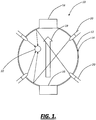
- the disinfection system 10 of the present invention includes a flow cell 12 that takes the form of an integrating sphere or the like.
- a flow cell 12 that takes the form of an integrating sphere or the like.
- the integrating sphere configuration is discussed at length herein, other configurations may also be utilized.
- the key consideration is that photons are repeatedly reflected within the flow cell 12 and that a uniform radiation field is formed for optimal disinfection with low intensity sources.
- the flow cell 12 comprises substantially curved and concave opposed interior surfaces. To restate, the flow cell 12 must not have internal "corners," and every point on the interior surface is visible from every other point on the interior surface. Ovoids, ellipsoids, cubes with rounded corners, etc. all fit these criteria.
- the flow cell 12 is made of plastic or the like for ease of manufacturing, and, in such cases where the material is not a good Lambertian scatterer, the interior surfaces thereof are coated with a Lambertian scattering material 14.
- the flow cell 12 is made of a metallic or other reflective or coated reflective material, such as aluminum, stainless steel, copper, etc., which may be anodized or otherwise coated with organic polymer, silicone, inorganic oxide, etc.
- the flow cell 12 is scalable and may have any suitable dimensions, on the order of millimeters to meters, for example.
- the flow cell 12 includes at least an inlet port 16 and an outlet port 18 manufactured into it that provides for the flow of a fluid 19 (i.e. a liquid or gas) from the inlet port 16 to the outlet port 18.
- a fluid 19 i.e. a liquid or gas
- the fluid 19 is not allowed to stagnate in any portion of the interior of the flow cell 12 for an appreciable period of time, as described in greater detail herein below, and the flow cell 12 is kept 100% full at all times.
- one or more point radiation sources 20 such as one or more UV optical sources, one or more deep-UV optical sources, one or more semiconductor optical sources, and/or one or more LED optical sources, are disposed within or partially or wholly through one or more ports (not illustrated) manufactured through the flow cell 12, preferably at symmetric positions.
- the one or more point radiation sources 20 are operable to disinfect the fluid 19 that is selectively exposed to them as the DNA of bacteria, viruses, cysts, and the like 22 in the fluid 19 absorbs the radiation generated and reflected in the flow cell 12 and the biological entities are thereby deactivated.
- Point radiation sources refer to small, roughly symmetrical radiation sources as compared to the other dimensions of the system.
- the disinfection system 10 of the present invention includes one or more mechanical baffles 24, mechanical stirring mechanisms, or the like, also optionally coated with Lambertian scattering material 14 and/or photocatalyzing material.
- This configuration is used to equilibrate and maximize the residence time of the fluid 19 in the interior volume of the flow cell 12.
- the goal is to optimize the design parameters (i.e. size of the flow cell 12, reflectance of Lambertian scattering material 14, residence time, and the radiant power of the one or more point radiation sources 20) to ensure that the bacterium or the like 22 receives a lethal dose of UV radiation while it is in the flow cell 12.
- a photocatalytic material 14 such as titanium dioxide (TiO 2 ), zinc oxide, zirconium dioxide, iron oxide, aluminum oxide, Fe(III)/Al 2 O 3 , cerium oxide, manganese oxide, titanium silicates, metal substituted silicates or aluminosilicates, and any other metal oxide, mixed metal oxide, and/or metal doped/supported metal oxide substrates (e.g.
- gold nanoparticles supported on silicon dioxide or titanium dioxide), or the like may be disposed on the inner surface(s) of the flow cell 12 or otherwise integrated with these surfaces to enhance the photo-oxidation, photo-reduction, and decontamination of contaminants on a near-field basis, including bacteria, pathogens, organic materials, halogenated compounds, biogenic compounds, metal ions, and/or biological agents.
- the photocatalyst material 14 could be suspended on a non-absorbing substrate (such as a fiber or a mesoporous or macroporous sol-gel, ormisil, polymer, or aeorogel) which occupies some of the interior region of the flow cell 12.
- a flow detector (not illustrated) or the like may be used before or after the flow cell 12 to turn off the one or more point radiation sources 20 during periods of no flow to maximize the life of the one or more point radiation sources 20, and the entire system may be coupled to an appropriate computer controller/processor (not illustrated) or the like that controls the overall function of the disinfection system 10.
- DNA has peak absorption at about 260 nm, but the absorption curve is broad, with the majority of UV absorption occurring between about 240 nm and about 280 nm.
- Low and medium pressure mercury lamps have emission peaks at about 253.7 nm, with medium pressure lamps having emission peaks which are narrow and sporadic across the peak microbicidal region of DNA.
- UV LEDs have broadband deep-UV emission and may be tailored for peak emission at about 260 nm to provide the maximum dose more effectively than mercury lamps.
- the LED wavelength may be shifted by varying the percent composition of aluminum within the Al x Ga (1-x) N active layer of the LED. LEDs with wavelengths centered at the peak of DNA absorption are recently commercially available.
- UV LEDs contain no mercury, which is extremely toxic such that discharge lamps containing mercury must be treated as hazardous waste and sent to an approved recycling facility when spent.
- mercury based sources produce emission lines at about 185 nm, which results in ozone production; ozone is corrosive and absorbs UV light, as well as being toxic.
- UV LEDs are mercury free solid state sources and may be manufactured to have no emission shorter than about 200 nm. In addition to being mercury free, UV LEDs have some distinct advantages over lamp sources. Lamps are bulky and require line voltage which is undesirable in POU systems, where line voltage is not always available where the unit would be positioned.
- mercury lamps have a start-up delay time associated with the creation of the plasma in the lamp envelop, which in turn heats the inert gas, which then vaporizes the mercury allowing the mercury and plasma ions to collide and excite the Hg to emission.
- UV LEDs may be turned on instantly and operated at a very fast on/off duty cycle to increase their lifetime.
- integrating spheres are typically used by optical scientists and spectroscopists to (1) efficiently collect light from a light source with a random radiation pattern and (2) create a diffuse source from the light so collected. This is accomplished through multiple reflections from the highly scattering interior walls of the integrating sphere, which are inherently reflective or coated with a Lambertian scattering material. In some cases, the collection is important, such as in the characterization of light bulbs. In other cases, the goal is to create a diffuse light source, such as for spectroscopy or photochemistry applications. In these applications, the inside volume of the integrating sphere is kept as empty as possible, usually containing only air.
- the integrating sphere As an enhanced sample holder for absorption spectroscopy, and as a product for characterizing samples, e.g. ocean or lake water has been characterized using this principle.
- a substantially or partially transparent medium such as air (or water)
- the light intensity inside the integrating sphere is everywhere the same, independent of direction. This is a unique feature of the integrating sphere, provided that the optical source (or sources) are small in area as compared to the interior surface area of the integrating sphere.
- a fluid containing a very small population of bacteria or the like is allowed to flow through the radiation filled integrating sphere.
- the following series of simple calculations demonstrates that, if the residence time of the fluid (e.g. water) is controlled, then the water may be disinfected using a relatively small number of commercially available UV LEDs or the like in conjunction with a properly designed integrating sphere flow cell.
- UV LEDs are a relatively recent emerging technology, and are ideally suited for optimization using an integrating sphere, since they are small (e.g. microns square) as compared to the inner surface of a sphere of nominal size (e.g. 2-inch radius).
- Earlier UV light sources such as mercury discharge lamps and the like, may not effectively be integrated with an integrating sphere flow cell in this manner due to their large form factor, among other considerations.
- Other methods for increasing residence time include: (1) the use of mechanical stirring; (2) the use of mechanical stirring in conjunction with non-spherical "dimples" or the like strategically located in the equatorial areas of the integrating sphere, for example; (3) utilizing directional flow via a perforated nozzle (i.e. showerhead) or the like at the water inlet; and (4) otherwise forcing the water to follow a circuitous path inside the sphere, by using a randomly bent tube, for example - the tube should be made from a UV transparent material, such as quartz or the like.
- the preferred way to maximize residence time may be to inject the incoming fluid into the flow cell in a direction parallel to a latitude in the southern hemisphere, for example, with the outlet perpendicular to the flow cell at the north pole, for example; this way the swirling fluid fills up the flow cell evenly from bottom to top.
- Optimum placement of inlet, outlet, baffles, etc. may be modeled using computational fluid dynamics (CFD). It should be noted that any non-uniformities in the integrating sphere, such as holes, dimples, baffles, etc. may degrade its optical performance.
- CFD computational fluid dynamics
- point radiation sources e.g. UV LEDs
- receivers i.e. bacteria, e.g e-coli bacteria
- the LED power is ⁇ s (typically mW)
- radius of the sphere is R
- flow rate is Q (typically cc per second)
- inner-surface reflectance of the sphere is k (%)
- reflectance is Lambertian
- f is the port fraction of the holes for sources, etc.
- the number of required LEDs scales with 1/R and also with 1/ ⁇ s .
- the radiant power of available LEDs is expected to increase over the time through continuous UV materials technological developments.
- the lifetime of UV LEDs is currently relatively short, on the order of about 300 hours. But LED operation may be optimized utilizing a pulsing algorithm or the like, and this lifetime is expected to continue to increase through continuous UV materials technological developments.
- the current generation of 0.5 mW UV LEDs consume about 100 mW of power each, so the total required system power for kitchen faucet UV water disinfection unit with a sphere of 2.5-inch radius is 2.5 watts.
- the power consumed by UV LEDs is also expected to continue to decrease through technological developments.
- a commercially available water disinfection unit with a conventional UV mercury lamp uses 14 watts for 3 gallons per minute of flow and a 10,000 hour lamp life.
- the Lambertian reflectance material must be non-toxic and highly reflecting.
- the sphere may be made of metal or plastic, and coated with metal, organic polymer, silicone, inorganic oxide, or anodized. Other materials are available with reasonably Lambertian characteristics, and reflectances on the order of k ⁇ 90% or more (e.g. certain aluminum coatings).
- photocatalytic materials such as titanium dioxide (TiO 2 ), zinc oxide, zirconium dioxide, iron oxide, aluminum oxide, Fe(III)/Al 2 O 3 , cerium oxide, manganese oxide, titanium silicates, metal substituted silicates or aluminosilicates, and any other metal oxide, mixed metal oxide, and/or metal doped/supported metal oxide substrates (e.g.
- gold nanoparticles supported on silicon dioxide or titanium dioxide), or the like may also be included inside the sphere or as part of the internal surface of the sphere to enhance photo-oxidation, photo-reduction, and the decontamination of water contaminants, including bacteria, pathogens, organic materials, halogenated compounds, biogenic compounds, metal ions, and/or biological agents.
- the photocatalyst inside the sphere would act as the "UV-receiver" instead of or in addition to the contaminant.
- the excited photocatalyst would interact with contaminants in the water stream to purify the water. It should be noted that this process may be staged with the radiation exposure process.
- Titanium dioxide for example, absorbs the near-UV effectively, having a wide bandgap of 3.2 eV; this absorption resulting in a photocatalytic reaction. Absorption of UV light leads to photoexcited electrons and holes, which are powerful reducing and oxidizing agents respectively (see eq. 6). The photoexcited holes react with adsorbed water to generate highly reactive hydoxy radicals ( ⁇ OH, see eq. 7). Simultaneously, the photoexcited electrons readily reduce adsorbed O 2 to generate superoxide radicals ( ⁇ O2-, see eq. 8). These reactive oxygen species (ROS), along with various side products, such as hydrogen peroxide, are believed to contribute to cell death in photocatalytic decontamination schemes.
- ROS reactive oxygen species
- the titanium dioxide or the like is immobilized along the walls of the highly reflecting integrating sphere.
- Fluoropolymer represents a potential matrix for coating the inside of the sphere due to its high reflectivity in the UV, its chemical inertness, and its ability to immobilize titanium dioxide.
- Titanium dioxide may also be immobilized into other organic and inorganic coatings, or deposited by sputtering or electron beam deposition.
- the continuous generation of reactive oxygen species has a long-term negative effect on most immobilization substrates.
- Bacterial DNA is known to have peak absorption at a wavelength of 260 nm and initial bacterial log reduction rates were determined using a planar array of 5 LEDs.
- the LEDs were used to irradiate a Petri dish with 20 mL of water infused with an e-coli strain. This set up was used to base line the dose received from UV LEDs to the standard mercury lamp sources currently used in water disinfection.
- a prototype FIS was also designed, built, and tested to validate the UV dose enhancement. The FIS design could hold about 230 mL of liquid and was fitted with 5 LEDs (Sphere 1) and 32 LEDs (Sphere 2).
- Mercury lamp source ( ⁇ 254 nm) dose requirements for 6 log reduction was found to be 30mJ/cm 2 .
- the NSF/ANSI 55 - 20072 standard requires a minimum dose of 40 mJ/cm 2 at 254 nm for Class A point of entry (POE) or point of use (POU) UV systems.
- the 5-260 nm LEDs Petri dish setup resulted in a greater than 6 log reduction in bacteria at a calculated dose of 61 mJ/cm 2 , and a greater than 5 log reduction at 36 mJ/cm 2 .
- the Petri dish configuration with 5 LEDs exposing 20 mL of bacteria laden water versus prototype Sphere 1 also with 5 LEDs exposing 230 mL of bacteria laden water, it was observed that the sphere prototype is capable of disinfecting 10 times the liquid volume of water than the Petri dish apparatus.
- the sphere flow cell was mechanically mixed on a slow moving orbital shaker while irradiating the bacteria infested water. Fluid dynamics modeling was performed to simulate water flow in the sphere for analysis of particle residence time. Two different models were used to investigate particle residence time and fluid flow in the sphere. Design A, the built prototype, had inlet and outlet ports horizontally aligned, while Design B had the inlet and outlet ports skewed horizontally with respect to each other. Both models had inlet and outlet pipes of 0.5-inch diameter and were modeled with a volumetric flow rate of 23.2 cm 3 /s, giving an inflow velocity of 0.183 m/s.
- Design A having a minimum PRT of 0.9 s while Design B had a minimum PRT of 1.4 s.
- Design A half of the particles were caught in an eddy current and hence not released within the first 2000 inches of travel in the sphere.
- Design B on the other hand, exhibited a more evenly distributed PRT with some particles revolving in eddy currents but not for longer than 50 seconds before exiting the sphere.
- the ideal material set for the spherical flow through integrating sphere would be non-toxic, easily machine-able (so that portals may be made for fluid flow and optical sources), of sufficient mechanical integrity and strength, inexpensive, leak-proof, and mass manufacturable. Additionally, the inner surface coating of the sphere should have appropriate optical scattering properties, ideally Lambertian, and with a reflectivity of 1.0 in the deep ultraviolet. A reflectivity of 1.0 is not achievable in practice, but certain materials are close.
- PTFE polytetrafluoroethylene
- PTFE acts somewhat as a diffuser, so high system reflectivity cannot be fully attained without a reflective outer layer.
- aluminum or the like provides an appropriate outer shell.
- Low density PTFE objects are formed by a labor intensive multistep process of (1) pressing PTFE powder into a solid form (e.g. a cube or a cylinder), (2) sintering at high temperature e.g. 500-600 degrees F, (3) machining parts with oil-free cutting tools in a clean room environment, and (4) encapsulating in a hard mechanical metal or polymer shell.
- An integrating sphere is typically made by hollowing out a cube of pressed and sintered PTFE. Since low density PTFE so prepared for deep-UV scattering has a porous structure, in the proposed application it may act as an "organic sponge", picking up any contaminants (e.g. minerals, trace organics) in the flowing water, and thus the optical properties of the sphere may be adversely affected. Nevertheless, a virgin integrating sphere flow cell made from low density PTFE provides an acceptable option in terms of optical properties, and therefore initial measurements made with such a device represent the entitlement of the system for a particular set of source power, source geometry, and inlet/outlet geometry.
- PTFE is also available in paint-on solutions with organic binders such as polyvinyl alcohol, however, these material are not as good of reflectors at wavelengths shorter than 300 nm due to absorption and degradation of the organic binder materials.
- organic binders also present toxicity concerns.
- Barium sulfate (BaSO4) is also an exemplary option and is commonly available in paint-on coatings which contain organic binder and solvent. Coatings from this type of material are specified to have reflectivity of 0.92 to 0.98 over the spectral range 300 nm to 1200 nm. However, for deep-UV (i.e. 260 nm), the decreasing reflectivity of the BaSO4 and the UV absorption of the organic binder combine to make BaSO4 less suitable for the current application.
- Aluminum is a good candidate material for the entire integrating sphere, being a good reflector in the UV, i.e. better then e.g. silver or gold.
- Aluminum has been extensively used as a reflective material in the extreme UV (EUV, i.e. shorter than 200 nm) in satellite mirror applications, and after performance has degraded due to oxidation during use, the reflectance may be regenerated by over-coating with more aluminum.
- EUV extreme UV
- MgF 2 magnesium fluoride
- regeneration is not required, and aluminum can sustain a reflectance of around 85% at 260 nm. This is typically accomplished by sputtering a thin (e.g.
- the spherical shell might be made of aluminum, and if so the scattering can be rendered more Lambertian by roughening through e.g. "bead blasting", essentially sandblasting with glass beads before the aluminum and MgF 2 thin films are deposited.
- Aluminum and MgF 2 could also be deposited in a similar way onto the inner surface of a plastic sphere.
- Magnesium fluoride raises concerns with respect to its toxicity, though it is approved in certain small quantities by the FDA as e.g. a bonding agent for aluminum foil. It is only slightly soluble in water.
- Polymers are attractive materials for flexible spherical shell prototype geometries and manufacturability, though their UV absorbance is high, and thus some kind of coating is required (e.g. aluminum, Al + MgF 2 , PTFE, etc.) to achieve a Lambertian inner scattering surface.
- Rapid prototyping technology such as solid state stereolithography (SLA) and selective laser sintering (SLS) can be used to quickly and cheaply construct hollow spherical prototypes with complex geometric features using engineering thermoplastics such as Accura and Duraform (nylon), respectively.
- CADs computer aided designs
- flow cell residence time Only the best performers are thus be prototyped and evaluated.
- prototypes can then be used as models to set up inexpensive injection molding processed for mass manufacturing from other thermoplastic materials and coatings, optimized for Lambertian scattering at 260 nm.
Landscapes
- Health & Medical Sciences (AREA)
- Life Sciences & Earth Sciences (AREA)
- Chemical & Material Sciences (AREA)
- General Health & Medical Sciences (AREA)
- Physics & Mathematics (AREA)
- Epidemiology (AREA)
- Animal Behavior & Ethology (AREA)
- Public Health (AREA)
- Veterinary Medicine (AREA)
- Pathology (AREA)
- Immunology (AREA)
- General Physics & Mathematics (AREA)
- Biochemistry (AREA)
- Analytical Chemistry (AREA)
- Spectroscopy & Molecular Physics (AREA)
- Organic Chemistry (AREA)
- Toxicology (AREA)
- Hydrology & Water Resources (AREA)
- Water Supply & Treatment (AREA)
- Environmental & Geological Engineering (AREA)
- Engineering & Computer Science (AREA)
- Chemical Kinetics & Catalysis (AREA)
- Apparatus For Disinfection Or Sterilisation (AREA)
- Physical Water Treatments (AREA)
- Optical Measuring Cells (AREA)
- Investigating Or Analysing Materials By Optical Means (AREA)
- Treatment Of Water By Oxidation Or Reduction (AREA)
- Catalysts (AREA)
Claims (16)
- Système (10) pour désinfecter un liquide (19), comprenant :une cellule de débit (12) comprenant un ou plusieurs orifices d'entrée (16) et un ou plusieurs orifices de sortie (18), dans lequel la cellule de débit (12) est configurée pour faire communiquer un liquide (19) à partir dudit ou desdits orifices d'entrée (16) à travers une partie intérieure de celle-ci jusqu'audit ou auxdits orifices de sortie (18), etune ou plusieurs sources de radiation ponctuelles (20) arrangées autour de la cellule de débit (12), dans lequel ladite ou lesdites sources de radiation ponctuelles (20) peuvent agir pour transmettre de la radiation au liquide (19) et désactiver une entité biologique (22) là-dedans,dans lequel une surface intérieure de la cellule de débit (12) peut agir pour refléter la radiation transmise au liquide (19) par ladite ou lesdites sources de radiation ponctuelles (20),caractérisé en ce que la cellule de débit (12) est une cavité intégrale comprenant des surfaces intérieures opposées courbées et concaves sans coins internes, dans lequel chaque point sur la surface intérieure est visible de chaque autre point sur la surface intérieure, etdans lequel ladite ou lesdites sources de radiation ponctuelles (20) sont arrangées autour de la cavité intégrale, etdans lequel la surface intérieure de la cellule de débit (12) peut agir pour refléter à plusieurs reprises la radiation transmise au liquide (19) par ladite ou lesdites sources de radiation ponctuelles (20), de manière que l'intensité de la radiation soit uniforme dans toute la partie intérieure de la cellule de débit (12).
- Système (10) selon la revendication 1, dans lequel la cellule de débit (12) comprend l'un ou plusieurs parmi un ellipsoïde intégral et une sphère intégrale.
- Système (10) selon la revendication 1, dans lequel ladite ou lesdites sources de radiation ponctuelles (20) comprennent une ou plusieurs parmi une ou plusieurs sources optiques à semi-conducteur, une ou plusieurs sources optiques à diode lumineuse, une ou plusieurs sources optiques ultraviolets, et une ou plusieurs sources optiques de rayons ultraviolets profonds.
- Système (10) selon la revendication 1, comprenant en outre un ou plusieurs déflecteurs mécaniques (24) ou mécanismes d'agitation se trouvant au sein de la partie intérieure de la cellule de débit (12) pour modifier sélectivement l'écoulement du liquide (19) à travers celle-ci.
- Système (10) selon la revendication 1, comprenant en outre un matériau photocatalyseur (14) se trouvant sur au moins une partie de la surface intérieure de la cellule de débit (12).
- Système (10) selon la revendication 4, comprenant en outre un matériau photocatalyseur (14) se trouvant sur au moins une partie d'une surface dudit ou desdits déflecteurs mécaniques (24) ou mécanismes d'agitation.
- Système (10) selon la revendication 1, comprenant en outre un régulateur pouvant agir pour sélectivement activer/désactiver ladite une ou plusieurs sources de radiation ponctuelles (20).
- Système (10) selon la revendication 1, comprenant en outre un régulateur pouvant agir pour sélectivement commander le temps de séjour du liquide (19) dans la partie intérieure de la cellule de débit (12).
- Procédé pour désinfecter un liquide (19) par irradiation, comprenant les étapes consistant à :procurer une cellule de débit (12) comprenant un ou plusieurs orifices d'entrée (16) et un ou plusieurs orifices de sortie (18), dans lequel la cellule de débit (12) est configurée pour faire communiquer un liquide (19) à partir dudit ou desdits orifices d'entrée (16) à travers une partie intérieure de celle-ci jusqu'audit ou auxdits orifices de sortie (18), etprocurer une ou plusieurs sources de radiation ponctuelles (20) arrangées autour de la cellule de débit (12), dans lequel ladite ou lesdites sources de radiation ponctuelles (20) peuvent agir pour transmettre de la radiation au liquide (19) et désactiver une entité biologique (22) là-dedans,dans lequel une surface intérieure de la cellule de débit (12) peut agir pour refléter la radiation transmise au liquide (19) par ladite ou lesdites sources de radiation ponctuelles (20),caractérisé en ce que la cellule de débit (12) utilisée est une cavité intégrale comprenant des surfaces intérieures opposées courbées et concaves sans coins internes, dans lequel chaque point sur la surface intérieure est visible de chaque autre point sur la surface intérieure, etdans lequel ladite ou lesdites sources de radiation ponctuelles (20) sont arrangées autour de la cavité intégrale, etdans lequel la surface intérieure de la cellule de débit (12) peut agir pour refléter à plusieurs reprises la radiation transmise au liquide (19) par ladite ou lesdites sources de radiation ponctuelles (20), de manière que l'intensité de la radiation soit uniforme dans toute la partie intérieure de la cellule de débit (12).
- Procédé selon la revendication 9, dans lequel la cellule de débit (12) comprend l'un ou plusieurs parmi un ellipsoïde intégral et une sphère intégrale.
- Procédé selon la revendication 9, dans lequel ladite ou lesdites sources de radiation ponctuelles (20) comprennent une ou plusieurs parmi une ou plusieurs sources optiques à semi-conducteur, une ou plusieurs sources optiques à diode lumineuse, une ou plusieurs sources optiques ultraviolets, et une ou plusieurs sources optiques de rayons ultraviolets profonds.
- Procédé selon la revendication 9, comprenant en outre l'étape consistant à procurer un ou plusieurs déflecteurs mécaniques (24) ou mécanismes d'agitation se trouvant au sein de la partie intérieure de la cellule de débit (12) pour modifier sélectivement l'écoulement du liquide (19) à travers celle-ci.
- Procédé selon la revendication 9, comprenant en outre l'étape consistant à procurer un matériau photocatalyseur (14) se trouvant sur au moins une partie de la surface intérieure de la cellule de débit (12).
- Procédé selon la revendication 12, comprenant en outre l'étape consistant à procurer un matériau photocatalyseur (14) se trouvant sur au moins une partie d'une surface dudit ou desdits déflecteurs mécaniques (24) ou mécanismes d'agitation.
- Procédé selon la revendication 9, comprenant en outre l'étape consistant à procurer un régulateur pouvant agir pour sélectivement activer/désactiver ladite une ou plusieurs sources de radiation ponctuelles (20).
- Procédé selon la revendication 9, comprenant en outre l'étape consistant à procurer un régulateur pouvant agir pour sélectivement commander le temps de séjour du liquide (19) dans la partie intérieure de la cellule de débit (12).
Applications Claiming Priority (2)
| Application Number | Priority Date | Filing Date | Title |
|---|---|---|---|
| US13902208P | 2008-12-19 | 2008-12-19 | |
| PCT/US2009/068765 WO2010071814A1 (fr) | 2008-12-19 | 2009-12-18 | Systèmes et procédés permettant de réaliser la désinfection bactérienne d'un fluide à l'aide de sources de radiation ponctuelles |
Publications (3)
| Publication Number | Publication Date |
|---|---|
| EP2379193A1 EP2379193A1 (fr) | 2011-10-26 |
| EP2379193A4 EP2379193A4 (fr) | 2012-09-12 |
| EP2379193B1 true EP2379193B1 (fr) | 2018-06-20 |
Family
ID=42269126
Family Applications (1)
| Application Number | Title | Priority Date | Filing Date |
|---|---|---|---|
| EP09833839.5A Active EP2379193B1 (fr) | 2008-12-19 | 2009-12-18 | Système et procédé permettant de réaliser la désinfection d'un fluide à l'aide de source de radiation ponctuelle |
Country Status (7)
| Country | Link |
|---|---|
| US (4) | US9855363B2 (fr) |
| EP (1) | EP2379193B1 (fr) |
| JP (1) | JP5432286B2 (fr) |
| KR (1) | KR101280571B1 (fr) |
| CN (2) | CN105963731A (fr) |
| CA (1) | CA2747200C (fr) |
| WO (1) | WO2010071814A1 (fr) |
Families Citing this family (68)
| Publication number | Priority date | Publication date | Assignee | Title |
|---|---|---|---|---|
| JP5432286B2 (ja) | 2008-12-19 | 2014-03-05 | ユニバーシティ オブ ノース カロライナ アット シャルロット | 点放射光源を用いて流体を殺菌するためのシステム及び方法 |
| WO2013064154A1 (fr) * | 2011-11-02 | 2013-05-10 | Syddansk Universitet | Dispositif de traitement de forme toroïdale pour la désinfection d'un fluide tel que l'air ou l'eau |
| US11000622B2 (en) | 2012-07-27 | 2021-05-11 | Aeroclean Technologies, Llc | UV sterilization apparatus, system, and method for forced-air patient heating systems |
| US8900519B2 (en) * | 2012-07-27 | 2014-12-02 | Mark D. Krosney | Air sterilization and disinfection apparatus and method |
| CN102895687B (zh) * | 2012-10-26 | 2014-12-24 | 昇瑞光电科技(上海)有限公司 | 高效深紫外线杀菌装置 |
| JP5812970B2 (ja) | 2012-11-19 | 2015-11-17 | 株式会社トクヤマ | 空気清浄装置 |
| US11338048B2 (en) | 2012-12-11 | 2022-05-24 | Aquisense Technologies Llc | Apparatus for irradiation |
| EP3461793B1 (fr) * | 2013-01-24 | 2022-03-02 | Atlantium Technologies Ltd. | Procédé et appareil de désinfection de liquides par une lumière émise par des diodes électroluminescentes |
| CA2905257C (fr) * | 2013-03-15 | 2022-03-15 | Atlantium Technologies Ltd. | Systeme et procede d'inactivation du virus de la necrose pancreatique infectieuse (vnpi) a l'aide de lumiere ultraviolette (uv) optimisee |
| CA2912666A1 (fr) | 2013-05-28 | 2014-12-04 | Ramot At Tel-Aviv University Ltd. | Detection de bases hydroxymethylcytosine |
| CN103951008B (zh) * | 2014-04-09 | 2019-05-10 | 青岛云路新能源科技有限公司 | 深紫外led杀菌装置 |
| DE102015108773B4 (de) * | 2014-06-03 | 2024-07-04 | Sensor Electronic Technology, Inc. | Ultraviolett-transparente Umhüllung |
| GB201420231D0 (en) * | 2014-11-13 | 2014-12-31 | Greenthread Ltd | Apparatus and method for water treatment |
| US9827340B2 (en) * | 2014-12-24 | 2017-11-28 | Maxim Integrated Products, Inc. | Mobile UV sterilization device and method |
| GB201502194D0 (en) * | 2015-02-10 | 2015-03-25 | Univ St Andrews | Scattered light integrating collector |
| US10180248B2 (en) | 2015-09-02 | 2019-01-15 | ProPhotonix Limited | LED lamp with sensing capabilities |
| KR20180061384A (ko) * | 2015-10-23 | 2018-06-07 | 클린코 바이오사이언스 그룹 엘엘씨 | Uv 멸균 장치, 시스템, 및 환자용 강제-공기 가열 시스템을 위한 방법 |
| JP6893397B2 (ja) * | 2016-06-22 | 2021-06-23 | 美浜株式会社 | 殺菌処理装置 |
| JP6419760B2 (ja) | 2016-08-30 | 2018-11-07 | 日機装株式会社 | 紫外光殺菌装置 |
| CN106277114A (zh) * | 2016-09-30 | 2017-01-04 | 圆融健康科技(深圳)有限公司 | 流动水杀菌设备 |
| US11312642B2 (en) | 2017-03-31 | 2022-04-26 | Industrial Technology Research Institute | Fluid sterilizing device |
| AU2018313244B2 (en) | 2017-08-11 | 2024-06-13 | AquiSense Incorporated | Apparatus and method for irradiation |
| US11406729B2 (en) | 2017-08-31 | 2022-08-09 | Aeroclean Technologies, Llc | Air treatment system and method |
| JP6978341B2 (ja) * | 2018-02-20 | 2021-12-08 | スタンレー電気株式会社 | 流体殺菌装置 |
| US10793454B1 (en) | 2018-02-22 | 2020-10-06 | United States Of America As Represented By The Secretary Of The Air Force | Water treatment system with ultraviolet LEDs and photo-catalysts |
| CN110316786A (zh) * | 2018-03-30 | 2019-10-11 | 旭化成株式会社 | 紫外线照射装置 |
| EP3578207B1 (fr) | 2018-04-20 | 2024-06-19 | Asahi Kasei Kabushiki Kaisha | Dispositif d'irradiation lumineuse d'ultraviolets |
| EP3756694A1 (fr) | 2018-04-20 | 2020-12-30 | Asahi Kasei Kabushiki Kaisha | Dispositif de rayonnement ultraviolet |
| DE102018124504A1 (de) * | 2018-10-04 | 2020-04-09 | Hytecon Ag | Anordnung für eine Vorrichtung zum Desinfizieren eines Fluids und Vorrichtung |
| EP3864384A4 (fr) * | 2018-10-08 | 2022-06-29 | Verifood Ltd. | Accessoires pour spectromètres optiques |
| CN109574130B (zh) * | 2018-12-19 | 2024-05-24 | 青岛杰生电气有限公司 | 过流式紫外线杀菌消毒单元 |
| KR102604128B1 (ko) * | 2019-02-08 | 2023-11-17 | 더블유.엘. 고어 앤드 어소시에이트스, 인코포레이티드 | 자외선 소독 시스템 |
| US11952293B2 (en) | 2019-03-07 | 2024-04-09 | International Water-Guard Industries Inc. | Apparatus for disinfecting a fluid |
| US12343668B2 (en) | 2019-04-22 | 2025-07-01 | Crystal Is, Inc. | Air disinfection chamber |
| US12037267B2 (en) | 2019-05-02 | 2024-07-16 | A.O. Smith Corporation | UV LED faucet flow cell |
| US12351478B2 (en) | 2019-05-16 | 2025-07-08 | Excelitas Canada, Inc. | System and method for manufacturing a system for filtering and disinfecting drinking water |
| WO2021020536A1 (fr) | 2019-07-31 | 2021-02-04 | 旭化成株式会社 | Appareil d'irradiation ultraviolette et procédé d'irradiation ultraviolette |
| KR20220038069A (ko) | 2019-07-31 | 2022-03-25 | 액세스 비지니스 그룹 인터내셔날 엘엘씨 | 수처리 시스템 |
| BR112022014445A2 (pt) | 2020-01-22 | 2022-10-11 | Strauss Water Ltd | Módulo de desinfecção líquida por radiação uv para desinfecção de água, dispensador de bebida, unidade de bico para água para dispensação de água desinfectada por uv e kit |
| US20230080010A1 (en) * | 2020-01-29 | 2023-03-16 | Valeo Systemes Thermiques | Nebulizer system for a motor vehicle |
| GB202001397D0 (en) | 2020-01-31 | 2020-03-18 | Odx Innovations Ltd | Apparatus, system and method for measuring properties of a sample |
| US10894726B1 (en) | 2020-02-12 | 2021-01-19 | Aquisense Technologies, Llc | Water disinfecting module, systems and methods |
| US11850336B2 (en) | 2020-05-22 | 2023-12-26 | Molekule Group, Inc. | UV sterilization apparatus, system, and method for aircraft air systems |
| RU2729292C1 (ru) * | 2020-05-29 | 2020-08-05 | Валерий Владимирович Крюков | Индивидуальные и мобильные устройства биологической защиты посредством облучения проточного воздуха ультрафиолетовым излучением |
| WO2021245307A1 (fr) * | 2020-06-03 | 2021-12-09 | Sergio Julio Morillas Valero | Machine, système et procédé de filtration, de désinfection et d'épuration du combustible pour des réservoirs contaminés |
| DE202020103352U1 (de) | 2020-06-10 | 2021-09-16 | BÄRO GmbH & Co. KG | Luftreinigungseinrichtung, raumlufttechnische Anlage, Lüftungs- oder Klimaanlage, Fahrzeug und Verwendung |
| EP3925633A1 (fr) * | 2020-06-19 | 2021-12-22 | Virobuster International GmbH | Dispositif de rayonnement destiné au rayonnement uv à un milieu en circulation |
| WO2022049048A1 (fr) * | 2020-09-03 | 2022-03-10 | Signify Holding B.V. | Dispositif électroluminescent pour désinfection d'objets |
| DE102021003829A1 (de) | 2020-09-06 | 2022-04-21 | Kastriot Merlaku | Impfstoff-Generator |
| KR102285032B1 (ko) * | 2020-09-10 | 2021-08-04 | 김영준 | 레이저를 이용한 살균장치 |
| CA3192709A1 (fr) | 2020-09-14 | 2022-03-17 | Mark D. Krosney | Assainisseur d'air integre et appareil de desinfection de surface |
| US20220105227A1 (en) * | 2020-10-02 | 2022-04-07 | Dynamis Energy, Llc | Dual chamber ultra-violet led device for use with face masks to disinfect end-user's inhaled and exhaled air |
| US11779675B2 (en) | 2020-10-19 | 2023-10-10 | Molekule Group, Inc. | Air sterilization insert for heating, ventilation, and air conditioning (HVAC) systems |
| WO2022090901A1 (fr) * | 2020-10-30 | 2022-05-05 | 3M Innovative Properties Company | Réflecteur de lumière ultraviolette c (uv-c) comprenant des films fluoropolymères |
| CN112499722A (zh) * | 2020-11-10 | 2021-03-16 | 佛山科学技术学院 | 一种环形结构紫外消毒反应器 |
| CN112499721B (zh) * | 2020-11-10 | 2022-08-16 | 佛山科学技术学院 | 一种具有柱形深紫外消毒辐射源的净水反应器 |
| CN112551637A (zh) * | 2020-11-11 | 2021-03-26 | 佛山科学技术学院 | 一种具有整流装置的环形双通道深紫外净水器 |
| WO2022103640A2 (fr) * | 2020-11-12 | 2022-05-19 | Wayne State University | Machine personnelle d'élimination par ultraviolet de germes respiratoires (pur gem) |
| CN112413796A (zh) * | 2020-11-25 | 2021-02-26 | 北京新风航天装备有限公司 | 一种基于紫外脉冲激光的空气净化用杀菌装置 |
| IT202000030899A1 (it) * | 2020-12-15 | 2022-06-15 | Istituto Naz Di Astrofisica | Dispositivo per la disinfezione di un flusso di fluido in un condotto mediante radiazioni uv-c |
| JP7607453B2 (ja) * | 2020-12-28 | 2024-12-27 | 株式会社エンプラス | 殺菌装置 |
| KR102632871B1 (ko) * | 2021-01-14 | 2024-02-05 | (주)엔디에스 | 반사체를 이용한 고효율 uv 살균 소독 장치 |
| JP7509074B2 (ja) * | 2021-04-14 | 2024-07-02 | 豊田合成株式会社 | 流体殺菌装置 |
| EP4104868A1 (fr) | 2021-06-17 | 2022-12-21 | Volvo Truck Corporation | Système de désinfection pour véhicule à moteur |
| JP7795304B2 (ja) * | 2021-06-30 | 2026-01-07 | 株式会社エンプラス | 殺菌装置 |
| IT202100028718A1 (it) * | 2021-11-11 | 2023-05-11 | Dario Russo | Apparato di sanificazione |
| KR102824577B1 (ko) * | 2023-02-20 | 2025-08-25 | 엘지전자 주식회사 | 살균 장치 |
| WO2026059899A1 (fr) | 2024-09-10 | 2026-03-19 | Aquisense Inc. | Appareil d'irradiation par ultraviolets avec élément de transfert thermique intégré |
Family Cites Families (44)
| Publication number | Priority date | Publication date | Assignee | Title |
|---|---|---|---|---|
| JPH063780Y2 (ja) * | 1988-12-09 | 1994-02-02 | 三菱重工業株式会社 | 容器の殺菌装置 |
| US5216251A (en) * | 1991-10-18 | 1993-06-01 | Matschke Arthur L | Apparatus and method for a bio-conditioning germicidal dryer |
| WO1993012488A1 (fr) | 1991-12-13 | 1993-06-24 | White Leonard R | Systeme et procede de logiciel pour analyse de mesures |
| US5251004A (en) * | 1992-03-13 | 1993-10-05 | Pdt Systems, Inc. | Integrating sphere power meter |
| US5874741A (en) * | 1995-10-03 | 1999-02-23 | Matschke; Arthur L. | Apparatus for germicidal cleansing of water |
| GB9611698D0 (en) | 1996-06-05 | 1996-08-07 | Iatros Ltd | Fluid processing |
| US6042720A (en) | 1996-12-19 | 2000-03-28 | Motorola, Inc. | Apparatus for storing and disinfecting a fluid |
| US6118134A (en) * | 1997-09-02 | 2000-09-12 | Justak; John F. | Optical mass gauge sensor having an energy per unit area of illumination detection |
| FI106424B (fi) | 1998-02-13 | 2001-01-31 | Nokia Networks Oy | Reititysalueen päivitys pakettiradioverkossa |
| US6172387B1 (en) | 1998-05-04 | 2001-01-09 | Micron Technology, Inc. | Semiconductor interconnection structure and method |
| US6514405B1 (en) | 1999-08-12 | 2003-02-04 | Eric L. Lifschitz | Portable water purifier with ultraviolet light source |
| US6429583B1 (en) | 1998-11-30 | 2002-08-06 | General Electric Company | Light emitting device with ba2mgsi2o7:eu2+, ba2sio4:eu2+, or (srxcay ba1-x-y)(a1zga1-z)2sr:eu2+phosphors |
| IL129564A (en) | 1999-04-23 | 2004-06-20 | Atlantium Lasers Ltd | A method for disinfecting and purifying liquids and gases and a device for its use |
| US6494617B1 (en) | 1999-04-30 | 2002-12-17 | General Electric Company | Status detection apparatus and method for fluid-filled electrical equipment |
| US6446027B1 (en) | 1999-09-17 | 2002-09-03 | General Electric Company | Intelligent analysis system and method for fluid-filled electrical equipment |
| US6766097B2 (en) | 2000-11-28 | 2004-07-20 | Remote Light, Inc. | UV portal-based appliances and containers |
| US6469308B1 (en) | 2001-05-01 | 2002-10-22 | Ryan M. Reed | Ultraviolet radiated water treatment tank |
| KR100891031B1 (ko) | 2001-11-02 | 2009-03-31 | 허니웰 인터내셔널 인코포레이티드 | 자외선 소독 장치 |
| US6841406B2 (en) | 2001-11-06 | 2005-01-11 | Edward Brittain Stokes | Methods and apparatus for a semiconductor device |
| WO2003084601A2 (fr) * | 2002-04-02 | 2003-10-16 | Lumerx, Inc. | Dispositifs et procedes utilisant la lumiere visible pour affaiblir et/ou tuer des micro-organismes dans le corps |
| US7118852B2 (en) * | 2002-04-11 | 2006-10-10 | Throwleigh Technologies, L.L.C. | Methods and apparatus for decontaminating fluids |
| US7125485B2 (en) | 2002-05-14 | 2006-10-24 | Jamel Hanbli | Water cooler/water purification system |
| US20040076544A1 (en) | 2002-10-09 | 2004-04-22 | Hung Dao | Method and apparatus for scanning and sterilizing mail received at a drop box |
| US6787782B1 (en) | 2003-04-23 | 2004-09-07 | B/E Aerospace, Inc. | Ultraviolet-light vehicle air cleaning system |
| WO2004103443A1 (fr) | 2003-05-22 | 2004-12-02 | Beijing Jingjing Medical Equipment Co., Ltd. | Methode permettant d'inactiver un virus dans le sang en circulation, et ses applications dans le traitement des maladies virales |
| IL157229A (en) * | 2003-08-04 | 2006-08-20 | Zamir Tribelsky | Method for energy coupling especially useful for disinfecting and various systems using it |
| US7554109B2 (en) | 2003-09-05 | 2009-06-30 | Dot Metrics Technology, Inc. | Quantum dot optoelectronic devices with nanoscale epitaxial lateral overgrowth and methods of manufacture |
| US7988923B2 (en) | 2004-02-23 | 2011-08-02 | Rgf Environmental Group, Inc. | Device, system and method for an advanced oxidation process using photohydroionization |
| US7403281B2 (en) | 2004-05-07 | 2008-07-22 | University Of Wyoming | Raman spectrometer |
| US20050274663A1 (en) * | 2004-05-24 | 2005-12-15 | Roitman Lipa L | [Air and Water Conditioning System and Filter Media] |
| US7993580B2 (en) * | 2004-08-24 | 2011-08-09 | Baxter International Inc. | Methods for the inactivation of microorganisms in biological fluids, flow through reactors and methods of controlling the light sum dose to effectively inactivate microorganisms in batch reactors |
| WO2006080216A1 (fr) * | 2005-01-26 | 2006-08-03 | Sumitomo Electric Industries, Ltd. | Dispositif d'emission en surface |
| EP1887297B1 (fr) * | 2005-05-26 | 2017-04-26 | Panasonic Corporation | Réfrigérateur |
| US7259846B2 (en) | 2005-08-30 | 2007-08-21 | Agilent Technologies, Inc. | Lab in a cuvette |
| KR101191809B1 (ko) | 2005-10-11 | 2012-10-16 | 유겐가이샤 케이투알 | 광촉매 반응수 생성 장치 |
| US8203124B2 (en) | 2007-04-27 | 2012-06-19 | Hand Held Products, Inc. | Sterilization apparatus |
| US7759854B2 (en) | 2007-05-30 | 2010-07-20 | Global Oled Technology Llc | Lamp with adjustable color |
| RU2010108227A (ru) * | 2007-08-07 | 2011-09-20 | ЛИ АНТИМАЙКРОБАЙАЛ СОЛЮШНЗ ЭлЭлСи (US) | Способы и устройства для защиты от микробиологического загрязнения с использованием газообразного очищенного пероксида водорода |
| JP5432286B2 (ja) | 2008-12-19 | 2014-03-05 | ユニバーシティ オブ ノース カロライナ アット シャルロット | 点放射光源を用いて流体を殺菌するためのシステム及び方法 |
| WO2011103269A1 (fr) | 2010-02-17 | 2011-08-25 | Dot Metrics Technologies, Inc. | Systèmes d'émission de rayonnement pour décontamination de fluide et de cuve |
| EP2683415B1 (fr) | 2011-03-11 | 2017-06-14 | Deutsches Rheuma-Forschungszentrum Berlin | Module de désinfection de cytomètre de flux |
| US20120246863A1 (en) | 2011-04-01 | 2012-10-04 | Douglas Ryan J | Control systems for uvc light source temperature and function in sanitizing device |
| CN104736261B (zh) | 2012-08-28 | 2017-06-16 | 传感器电子技术股份有限公司 | 包括紫外线照明的存储系统 |
| US11338048B2 (en) | 2012-12-11 | 2022-05-24 | Aquisense Technologies Llc | Apparatus for irradiation |
-
2009
- 2009-12-18 JP JP2011542492A patent/JP5432286B2/ja active Active
- 2009-12-18 KR KR1020117014119A patent/KR101280571B1/ko active Active
- 2009-12-18 CA CA2747200A patent/CA2747200C/fr active Active
- 2009-12-18 EP EP09833839.5A patent/EP2379193B1/fr active Active
- 2009-12-18 CN CN201610465051.0A patent/CN105963731A/zh active Pending
- 2009-12-18 WO PCT/US2009/068765 patent/WO2010071814A1/fr not_active Ceased
- 2009-12-18 CN CN2009801547766A patent/CN102281933A/zh active Pending
-
2011
- 2011-06-17 US US13/163,055 patent/US9855363B2/en active Active
-
2014
- 2014-05-07 US US14/271,859 patent/US9976953B2/en active Active
-
2017
- 2017-06-23 US US15/631,050 patent/US9861721B2/en active Active
-
2018
- 2018-01-08 US US15/864,095 patent/US10029026B2/en active Active
Also Published As
| Publication number | Publication date |
|---|---|
| US20120318749A1 (en) | 2012-12-20 |
| US9855363B2 (en) | 2018-01-02 |
| CA2747200A1 (fr) | 2010-06-24 |
| KR101280571B1 (ko) | 2013-07-02 |
| US20180011020A9 (en) | 2018-01-11 |
| EP2379193A1 (fr) | 2011-10-26 |
| EP2379193A4 (fr) | 2012-09-12 |
| KR20110127115A (ko) | 2011-11-24 |
| WO2010071814A1 (fr) | 2010-06-24 |
| US20180147314A1 (en) | 2018-05-31 |
| US10029026B2 (en) | 2018-07-24 |
| JP2012512723A (ja) | 2012-06-07 |
| CN105963731A (zh) | 2016-09-28 |
| US9861721B2 (en) | 2018-01-09 |
| JP5432286B2 (ja) | 2014-03-05 |
| US20140240695A1 (en) | 2014-08-28 |
| CN102281933A (zh) | 2011-12-14 |
| US9976953B2 (en) | 2018-05-22 |
| US20180008741A9 (en) | 2018-01-11 |
| CA2747200C (fr) | 2013-05-28 |
| US20170290943A1 (en) | 2017-10-12 |
Similar Documents
| Publication | Publication Date | Title |
|---|---|---|
| US10029026B2 (en) | Systems and methods for performing the bacterial disinfection of a fluid using point radiation sources | |
| AU2006285220B2 (en) | Ultraviolet light treatment chamber | |
| US10093558B2 (en) | Ultraviolet transparent enclosure | |
| US9802840B2 (en) | Ultraviolet water disinfection system | |
| JP5844250B2 (ja) | 紫外光処理チャンバ | |
| EP2234926B1 (fr) | Chambre de traitement par rayonnement ultraviolet | |
| US12128149B2 (en) | Humidifier disinfection using ultraviolet light | |
| WO2008113128A1 (fr) | Procédé et appareil permettant d'effectuer une transformation prédéterminée | |
| AU2014214056B2 (en) | UV apparatus |
Legal Events
| Date | Code | Title | Description |
|---|---|---|---|
| PUAI | Public reference made under article 153(3) epc to a published international application that has entered the european phase |
Free format text: ORIGINAL CODE: 0009012 |
|
| 17P | Request for examination filed |
Effective date: 20110615 |
|
| AK | Designated contracting states |
Kind code of ref document: A1 Designated state(s): AT BE BG CH CY CZ DE DK EE ES FI FR GB GR HR HU IE IS IT LI LT LU LV MC MK MT NL NO PL PT RO SE SI SK SM TR |
|
| DAX | Request for extension of the european patent (deleted) | ||
| A4 | Supplementary search report drawn up and despatched |
Effective date: 20120809 |
|
| RIC1 | Information provided on ipc code assigned before grant |
Ipc: B01D 15/00 20060101AFI20120803BHEP Ipc: A61L 9/20 20060101ALI20120803BHEP Ipc: A61L 2/10 20060101ALI20120803BHEP |
|
| 17Q | First examination report despatched |
Effective date: 20141110 |
|
| STAA | Information on the status of an ep patent application or granted ep patent |
Free format text: STATUS: EXAMINATION IS IN PROGRESS |
|
| REG | Reference to a national code |
Ref country code: DE Ref legal event code: R079 Ref document number: 602009052891 Country of ref document: DE Free format text: PREVIOUS MAIN CLASS: B01D0015000000 Ipc: A61L0002100000 |
|
| RIC1 | Information provided on ipc code assigned before grant |
Ipc: A61L 2/10 20060101AFI20171211BHEP Ipc: C02F 1/32 20060101ALI20171211BHEP Ipc: B01D 15/00 20060101ALI20171211BHEP Ipc: A61L 9/20 20060101ALI20171211BHEP |
|
| GRAP | Despatch of communication of intention to grant a patent |
Free format text: ORIGINAL CODE: EPIDOSNIGR1 |
|
| STAA | Information on the status of an ep patent application or granted ep patent |
Free format text: STATUS: GRANT OF PATENT IS INTENDED |
|
| INTG | Intention to grant announced |
Effective date: 20180119 |
|
| INTG | Intention to grant announced |
Effective date: 20180119 |
|
| RAP1 | Party data changed (applicant data changed or rights of an application transferred) |
Owner name: UNIVERSITY OF NORTH CAROLINA AT CHARLOTTE Owner name: AQUISENSE TECHNOLOGIES LLC |
|
| GRAS | Grant fee paid |
Free format text: ORIGINAL CODE: EPIDOSNIGR3 |
|
| GRAA | (expected) grant |
Free format text: ORIGINAL CODE: 0009210 |
|
| STAA | Information on the status of an ep patent application or granted ep patent |
Free format text: STATUS: THE PATENT HAS BEEN GRANTED |
|
| AK | Designated contracting states |
Kind code of ref document: B1 Designated state(s): AT BE BG CH CY CZ DE DK EE ES FI FR GB GR HR HU IE IS IT LI LT LU LV MC MK MT NL NO PL PT RO SE SI SK SM TR |
|
| REG | Reference to a national code |
Ref country code: GB Ref legal event code: FG4D |
|
| REG | Reference to a national code |
Ref country code: IE Ref legal event code: FG4D |
|
| REG | Reference to a national code |
Ref country code: CH Ref legal event code: NV Representative=s name: KASCHE AND PARTNER AG, CH |
|
| REG | Reference to a national code |
Ref country code: AT Ref legal event code: REF Ref document number: 1010094 Country of ref document: AT Kind code of ref document: T Effective date: 20180715 |
|
| REG | Reference to a national code |
Ref country code: DE Ref legal event code: R096 Ref document number: 602009052891 Country of ref document: DE |
|
| REG | Reference to a national code |
Ref country code: SE Ref legal event code: TRGR |
|
| REG | Reference to a national code |
Ref country code: NL Ref legal event code: MP Effective date: 20180620 |
|
| PG25 | Lapsed in a contracting state [announced via postgrant information from national office to epo] |
Ref country code: NO Free format text: LAPSE BECAUSE OF FAILURE TO SUBMIT A TRANSLATION OF THE DESCRIPTION OR TO PAY THE FEE WITHIN THE PRESCRIBED TIME-LIMIT Effective date: 20180920 Ref country code: FI Free format text: LAPSE BECAUSE OF FAILURE TO SUBMIT A TRANSLATION OF THE DESCRIPTION OR TO PAY THE FEE WITHIN THE PRESCRIBED TIME-LIMIT Effective date: 20180620 Ref country code: BG Free format text: LAPSE BECAUSE OF FAILURE TO SUBMIT A TRANSLATION OF THE DESCRIPTION OR TO PAY THE FEE WITHIN THE PRESCRIBED TIME-LIMIT Effective date: 20180920 Ref country code: LT Free format text: LAPSE BECAUSE OF FAILURE TO SUBMIT A TRANSLATION OF THE DESCRIPTION OR TO PAY THE FEE WITHIN THE PRESCRIBED TIME-LIMIT Effective date: 20180620 |
|
| REG | Reference to a national code |
Ref country code: LT Ref legal event code: MG4D |
|
| PG25 | Lapsed in a contracting state [announced via postgrant information from national office to epo] |
Ref country code: HR Free format text: LAPSE BECAUSE OF FAILURE TO SUBMIT A TRANSLATION OF THE DESCRIPTION OR TO PAY THE FEE WITHIN THE PRESCRIBED TIME-LIMIT Effective date: 20180620 Ref country code: GR Free format text: LAPSE BECAUSE OF FAILURE TO SUBMIT A TRANSLATION OF THE DESCRIPTION OR TO PAY THE FEE WITHIN THE PRESCRIBED TIME-LIMIT Effective date: 20180921 Ref country code: LV Free format text: LAPSE BECAUSE OF FAILURE TO SUBMIT A TRANSLATION OF THE DESCRIPTION OR TO PAY THE FEE WITHIN THE PRESCRIBED TIME-LIMIT Effective date: 20180620 |
|
| REG | Reference to a national code |
Ref country code: AT Ref legal event code: MK05 Ref document number: 1010094 Country of ref document: AT Kind code of ref document: T Effective date: 20180620 |
|
| PG25 | Lapsed in a contracting state [announced via postgrant information from national office to epo] |
Ref country code: NL Free format text: LAPSE BECAUSE OF FAILURE TO SUBMIT A TRANSLATION OF THE DESCRIPTION OR TO PAY THE FEE WITHIN THE PRESCRIBED TIME-LIMIT Effective date: 20180620 |
|
| PG25 | Lapsed in a contracting state [announced via postgrant information from national office to epo] |
Ref country code: SK Free format text: LAPSE BECAUSE OF FAILURE TO SUBMIT A TRANSLATION OF THE DESCRIPTION OR TO PAY THE FEE WITHIN THE PRESCRIBED TIME-LIMIT Effective date: 20180620 Ref country code: RO Free format text: LAPSE BECAUSE OF FAILURE TO SUBMIT A TRANSLATION OF THE DESCRIPTION OR TO PAY THE FEE WITHIN THE PRESCRIBED TIME-LIMIT Effective date: 20180620 Ref country code: IS Free format text: LAPSE BECAUSE OF FAILURE TO SUBMIT A TRANSLATION OF THE DESCRIPTION OR TO PAY THE FEE WITHIN THE PRESCRIBED TIME-LIMIT Effective date: 20181020 Ref country code: CZ Free format text: LAPSE BECAUSE OF FAILURE TO SUBMIT A TRANSLATION OF THE DESCRIPTION OR TO PAY THE FEE WITHIN THE PRESCRIBED TIME-LIMIT Effective date: 20180620 Ref country code: AT Free format text: LAPSE BECAUSE OF FAILURE TO SUBMIT A TRANSLATION OF THE DESCRIPTION OR TO PAY THE FEE WITHIN THE PRESCRIBED TIME-LIMIT Effective date: 20180620 Ref country code: EE Free format text: LAPSE BECAUSE OF FAILURE TO SUBMIT A TRANSLATION OF THE DESCRIPTION OR TO PAY THE FEE WITHIN THE PRESCRIBED TIME-LIMIT Effective date: 20180620 Ref country code: PL Free format text: LAPSE BECAUSE OF FAILURE TO SUBMIT A TRANSLATION OF THE DESCRIPTION OR TO PAY THE FEE WITHIN THE PRESCRIBED TIME-LIMIT Effective date: 20180620 |
|
| PG25 | Lapsed in a contracting state [announced via postgrant information from national office to epo] |
Ref country code: SM Free format text: LAPSE BECAUSE OF FAILURE TO SUBMIT A TRANSLATION OF THE DESCRIPTION OR TO PAY THE FEE WITHIN THE PRESCRIBED TIME-LIMIT Effective date: 20180620 Ref country code: ES Free format text: LAPSE BECAUSE OF FAILURE TO SUBMIT A TRANSLATION OF THE DESCRIPTION OR TO PAY THE FEE WITHIN THE PRESCRIBED TIME-LIMIT Effective date: 20180620 |
|
| REG | Reference to a national code |
Ref country code: DE Ref legal event code: R097 Ref document number: 602009052891 Country of ref document: DE |
|
| PLBE | No opposition filed within time limit |
Free format text: ORIGINAL CODE: 0009261 |
|
| STAA | Information on the status of an ep patent application or granted ep patent |
Free format text: STATUS: NO OPPOSITION FILED WITHIN TIME LIMIT |
|
| 26N | No opposition filed |
Effective date: 20190321 |
|
| PG25 | Lapsed in a contracting state [announced via postgrant information from national office to epo] |
Ref country code: DK Free format text: LAPSE BECAUSE OF FAILURE TO SUBMIT A TRANSLATION OF THE DESCRIPTION OR TO PAY THE FEE WITHIN THE PRESCRIBED TIME-LIMIT Effective date: 20180620 |
|
| PG25 | Lapsed in a contracting state [announced via postgrant information from national office to epo] |
Ref country code: LU Free format text: LAPSE BECAUSE OF NON-PAYMENT OF DUE FEES Effective date: 20181218 Ref country code: MC Free format text: LAPSE BECAUSE OF FAILURE TO SUBMIT A TRANSLATION OF THE DESCRIPTION OR TO PAY THE FEE WITHIN THE PRESCRIBED TIME-LIMIT Effective date: 20180620 Ref country code: SI Free format text: LAPSE BECAUSE OF FAILURE TO SUBMIT A TRANSLATION OF THE DESCRIPTION OR TO PAY THE FEE WITHIN THE PRESCRIBED TIME-LIMIT Effective date: 20180620 |
|
| REG | Reference to a national code |
Ref country code: IE Ref legal event code: MM4A |
|
| REG | Reference to a national code |
Ref country code: BE Ref legal event code: MM Effective date: 20181231 |
|
| PG25 | Lapsed in a contracting state [announced via postgrant information from national office to epo] |
Ref country code: IE Free format text: LAPSE BECAUSE OF NON-PAYMENT OF DUE FEES Effective date: 20181218 |
|
| PG25 | Lapsed in a contracting state [announced via postgrant information from national office to epo] |
Ref country code: BE Free format text: LAPSE BECAUSE OF NON-PAYMENT OF DUE FEES Effective date: 20181231 |
|
| PG25 | Lapsed in a contracting state [announced via postgrant information from national office to epo] |
Ref country code: MT Free format text: LAPSE BECAUSE OF NON-PAYMENT OF DUE FEES Effective date: 20181218 |
|
| PG25 | Lapsed in a contracting state [announced via postgrant information from national office to epo] |
Ref country code: TR Free format text: LAPSE BECAUSE OF FAILURE TO SUBMIT A TRANSLATION OF THE DESCRIPTION OR TO PAY THE FEE WITHIN THE PRESCRIBED TIME-LIMIT Effective date: 20180620 |
|
| PG25 | Lapsed in a contracting state [announced via postgrant information from national office to epo] |
Ref country code: PT Free format text: LAPSE BECAUSE OF FAILURE TO SUBMIT A TRANSLATION OF THE DESCRIPTION OR TO PAY THE FEE WITHIN THE PRESCRIBED TIME-LIMIT Effective date: 20180620 |
|
| PG25 | Lapsed in a contracting state [announced via postgrant information from national office to epo] |
Ref country code: HU Free format text: LAPSE BECAUSE OF FAILURE TO SUBMIT A TRANSLATION OF THE DESCRIPTION OR TO PAY THE FEE WITHIN THE PRESCRIBED TIME-LIMIT; INVALID AB INITIO Effective date: 20091218 Ref country code: CY Free format text: LAPSE BECAUSE OF FAILURE TO SUBMIT A TRANSLATION OF THE DESCRIPTION OR TO PAY THE FEE WITHIN THE PRESCRIBED TIME-LIMIT Effective date: 20180620 Ref country code: MK Free format text: LAPSE BECAUSE OF NON-PAYMENT OF DUE FEES Effective date: 20180620 |
|
| REG | Reference to a national code |
Ref country code: GB Ref legal event code: 732E Free format text: REGISTERED BETWEEN 20250213 AND 20250219 |
|
| REG | Reference to a national code |
Ref country code: DE Ref legal event code: R081 Ref document number: 602009052891 Country of ref document: DE Owner name: UNIVERSITY OF NORTH CAROLINA AT CHARLOTTE, CHA, US Free format text: FORMER OWNERS: AQUISENSE TECHNOLOGIES LLC, ERLANGER, KY., US; UNIVERSITY OF NORTH CAROLINA AT CHARLOTTE, CHARLOTTE, N.C., US Ref country code: DE Ref legal event code: R081 Ref document number: 602009052891 Country of ref document: DE Owner name: AQUISENSE INC., ERLANGER, US Free format text: FORMER OWNERS: AQUISENSE TECHNOLOGIES LLC, ERLANGER, KY., US; UNIVERSITY OF NORTH CAROLINA AT CHARLOTTE, CHARLOTTE, N.C., US |
|
| PGFP | Annual fee paid to national office [announced via postgrant information from national office to epo] |
Ref country code: CH Payment date: 20250108 Year of fee payment: 16 |
|
| REG | Reference to a national code |
Ref country code: CH Ref legal event code: R17 Free format text: ST27 STATUS EVENT CODE: U-0-0-R10-R17 (AS PROVIDED BY THE NATIONAL OFFICE) Effective date: 20251212 |
|
| REG | Reference to a national code |
Ref country code: CH Ref legal event code: U11 Free format text: ST27 STATUS EVENT CODE: U-0-0-U10-U11 (AS PROVIDED BY THE NATIONAL OFFICE) Effective date: 20260101 |
|
| PGFP | Annual fee paid to national office [announced via postgrant information from national office to epo] |
Ref country code: GB Payment date: 20251229 Year of fee payment: 17 |
|
| PGFP | Annual fee paid to national office [announced via postgrant information from national office to epo] |
Ref country code: IT Payment date: 20251219 Year of fee payment: 17 |
|
| PGFP | Annual fee paid to national office [announced via postgrant information from national office to epo] |
Ref country code: FR Payment date: 20251226 Year of fee payment: 17 |
|
| PGFP | Annual fee paid to national office [announced via postgrant information from national office to epo] |
Ref country code: SE Payment date: 20251227 Year of fee payment: 17 |
|
| PGFP | Annual fee paid to national office [announced via postgrant information from national office to epo] |
Ref country code: DE Payment date: 20251229 Year of fee payment: 17 |