EP2379892B1 - Vollständig untertauchbare integrierte elektroölpumpe - Google Patents
Vollständig untertauchbare integrierte elektroölpumpe Download PDFInfo
- Publication number
- EP2379892B1 EP2379892B1 EP09824319.9A EP09824319A EP2379892B1 EP 2379892 B1 EP2379892 B1 EP 2379892B1 EP 09824319 A EP09824319 A EP 09824319A EP 2379892 B1 EP2379892 B1 EP 2379892B1
- Authority
- EP
- European Patent Office
- Prior art keywords
- pump
- stator
- rotor
- electric pump
- outer rotor
- Prior art date
- Legal status (The legal status is an assumption and is not a legal conclusion. Google has not performed a legal analysis and makes no representation as to the accuracy of the status listed.)
- Active
Links
Images


Classifications
-
- F—MECHANICAL ENGINEERING; LIGHTING; HEATING; WEAPONS; BLASTING
- F04—POSITIVE - DISPLACEMENT MACHINES FOR LIQUIDS; PUMPS FOR LIQUIDS OR ELASTIC FLUIDS
- F04C—ROTARY-PISTON, OR OSCILLATING-PISTON, POSITIVE-DISPLACEMENT MACHINES FOR LIQUIDS; ROTARY-PISTON, OR OSCILLATING-PISTON, POSITIVE-DISPLACEMENT PUMPS
- F04C2/00—Rotary-piston machines or pumps
- F04C2/08—Rotary-piston machines or pumps of intermeshing-engagement type, i.e. with engagement of co-operating members similar to that of toothed gearing
- F04C2/10—Rotary-piston machines or pumps of intermeshing-engagement type, i.e. with engagement of co-operating members similar to that of toothed gearing of internal-axis type with the outer member having more teeth or tooth-equivalents, e.g. rollers, than the inner member
-
- F—MECHANICAL ENGINEERING; LIGHTING; HEATING; WEAPONS; BLASTING
- F04—POSITIVE - DISPLACEMENT MACHINES FOR LIQUIDS; PUMPS FOR LIQUIDS OR ELASTIC FLUIDS
- F04C—ROTARY-PISTON, OR OSCILLATING-PISTON, POSITIVE-DISPLACEMENT MACHINES FOR LIQUIDS; ROTARY-PISTON, OR OSCILLATING-PISTON, POSITIVE-DISPLACEMENT PUMPS
- F04C13/00—Adaptations of machines or pumps for special use, e.g. for extremely high pressures
- F04C13/008—Pumps for submersible use, i.e. down-hole pumping
-
- F—MECHANICAL ENGINEERING; LIGHTING; HEATING; WEAPONS; BLASTING
- F04—POSITIVE - DISPLACEMENT MACHINES FOR LIQUIDS; PUMPS FOR LIQUIDS OR ELASTIC FLUIDS
- F04C—ROTARY-PISTON, OR OSCILLATING-PISTON, POSITIVE-DISPLACEMENT MACHINES FOR LIQUIDS; ROTARY-PISTON, OR OSCILLATING-PISTON, POSITIVE-DISPLACEMENT PUMPS
- F04C11/00—Combinations of two or more machines or pumps, each being of rotary-piston or oscillating-piston type; Pumping installations
- F04C11/008—Enclosed motor pump units
-
- F—MECHANICAL ENGINEERING; LIGHTING; HEATING; WEAPONS; BLASTING
- F04—POSITIVE - DISPLACEMENT MACHINES FOR LIQUIDS; PUMPS FOR LIQUIDS OR ELASTIC FLUIDS
- F04C—ROTARY-PISTON, OR OSCILLATING-PISTON, POSITIVE-DISPLACEMENT MACHINES FOR LIQUIDS; ROTARY-PISTON, OR OSCILLATING-PISTON, POSITIVE-DISPLACEMENT PUMPS
- F04C15/00—Component parts, details or accessories of machines, pumps or pumping installations, not provided for in groups F04C2/00 - F04C14/00
- F04C15/0057—Driving elements, brakes, couplings, transmission specially adapted for machines or pumps
- F04C15/008—Prime movers
-
- F—MECHANICAL ENGINEERING; LIGHTING; HEATING; WEAPONS; BLASTING
- F04—POSITIVE - DISPLACEMENT MACHINES FOR LIQUIDS; PUMPS FOR LIQUIDS OR ELASTIC FLUIDS
- F04C—ROTARY-PISTON, OR OSCILLATING-PISTON, POSITIVE-DISPLACEMENT MACHINES FOR LIQUIDS; ROTARY-PISTON, OR OSCILLATING-PISTON, POSITIVE-DISPLACEMENT PUMPS
- F04C2/00—Rotary-piston machines or pumps
- F04C2/08—Rotary-piston machines or pumps of intermeshing-engagement type, i.e. with engagement of co-operating members similar to that of toothed gearing
- F04C2/10—Rotary-piston machines or pumps of intermeshing-engagement type, i.e. with engagement of co-operating members similar to that of toothed gearing of internal-axis type with the outer member having more teeth or tooth-equivalents, e.g. rollers, than the inner member
- F04C2/102—Rotary-piston machines or pumps of intermeshing-engagement type, i.e. with engagement of co-operating members similar to that of toothed gearing of internal-axis type with the outer member having more teeth or tooth-equivalents, e.g. rollers, than the inner member the two members rotating simultaneously around their respective axes
-
- H—ELECTRICITY
- H02—GENERATION; CONVERSION OR DISTRIBUTION OF ELECTRIC POWER
- H02K—DYNAMO-ELECTRIC MACHINES
- H02K41/00—Propulsion systems in which a rigid body is moved along a path due to dynamo-electric interaction between the body and a magnetic field travelling along the path
- H02K41/06—Rolling motors, i.e. motors having the rotor axis parallel to the stator axis and following a circular path as the rotor rolls around the inside or outside of the stator ; Nutating motors, i.e. having the rotor axis parallel to the stator axis inclined with respect to the stator axis and performing a nutational movement as the rotor rolls on the stator
-
- H—ELECTRICITY
- H02—GENERATION; CONVERSION OR DISTRIBUTION OF ELECTRIC POWER
- H02K—DYNAMO-ELECTRIC MACHINES
- H02K5/00—Casings; Enclosures; Supports
- H02K5/04—Casings or enclosures characterised by the shape, form or construction thereof
- H02K5/12—Casings or enclosures characterised by the shape, form or construction thereof specially adapted for operating in liquid or gas
-
- H—ELECTRICITY
- H02—GENERATION; CONVERSION OR DISTRIBUTION OF ELECTRIC POWER
- H02K—DYNAMO-ELECTRIC MACHINES
- H02K7/00—Arrangements for handling mechanical energy structurally associated with dynamo-electric machines, e.g. structural association with mechanical driving motors or auxiliary dynamo-electric machines
- H02K7/14—Structural association with mechanical loads, e.g. with hand-held machine tools or fans
-
- F—MECHANICAL ENGINEERING; LIGHTING; HEATING; WEAPONS; BLASTING
- F04—POSITIVE - DISPLACEMENT MACHINES FOR LIQUIDS; PUMPS FOR LIQUIDS OR ELASTIC FLUIDS
- F04C—ROTARY-PISTON, OR OSCILLATING-PISTON, POSITIVE-DISPLACEMENT MACHINES FOR LIQUIDS; ROTARY-PISTON, OR OSCILLATING-PISTON, POSITIVE-DISPLACEMENT PUMPS
- F04C2240/00—Components
- F04C2240/80—Other components
- F04C2240/808—Electronic circuits (e.g. inverters) installed inside the machine
Definitions
- the present disclosure generally relates to an electric motor driven pump. More particularly, a submersible integrated electric oil pump is described.
- a number of electric pumps have been disclosed combining an electric motor and a gerotor pump.
- U.S. Patent No. 7,156,623 describes an electric motor and a gerotor pump that are usable separately or in combination with one another. While this concept may provide a pumping function, redundancies exist, possibly negatively effecting the cost, size and weight of the fluid pump.
- U.S. Patent No. 7,314,352 describes a pump having an integrated electric motor.
- the electric motor includes a stator having a core with a plurality of ring-shaped steel plates and a wire coil wound about the core. The plates and coil are encapsulated within a block of resin.
- the resin spaces the stator apart from permanent magnets of the motor armature a distance greater than desired. Motor efficiency decreases as the distance between the stator and armature increases.
- use of the resin increases the challenge of controlling the end face clearances of the rotating components due to the difficulty of machining the resin. Accordingly, a need in the art exists for an improved fully submersible integrated electric oil pump.
- a submersible electric pump includes a housing adapted to be submerged within a fluid to be pumped having apertures extending therethrough.
- An electric motor stator is positioned within the housing in communication with the apertures and is adapted to be in contact with the fluid.
- Inner and outer pump rotors are positioned within the housing in meshed engagement with one another to pump fluid when rotated.
- a plurality of permanent magnets are fixed for rotation with the outer rotor.
- a submersible electric pump in another form, includes a first shell having a substantially planar first pump surface and a second shell fixed to the first shell to define a housing.
- the second shell has a substantially planar second pump surface spaced apart from and extending substantially parallel to the first pump surface.
- a gerotor pump includes an inner rotor and an outer rotor. Each rotor includes opposite faces positioned adjacent the first and second pump surfaces.
- a rotor shaft includes spaced apart shoulders engaging each of the first and second shells to define a predetermined spacing between the first and second pump surfaces.
- An electric motor stator is positioned within the housing. Permanent magnets are fixed for rotation with the outer rotor and are positioned proximate the stator.
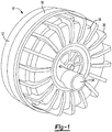
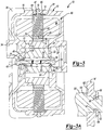
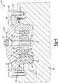
- FIGS 1-3 depict a submersible integrated electric oil pump identified at reference numeral 10.
- Pump 10 includes a housing 12 having a base 14, a cover 16 and an intermediate ring 18. Each of base 14 and cover 16 may be formed as aluminum die castings. Intermediate ring 18 is sandwiched between base 14 and cover 16 to compensate for the coefficient of thermal expansion of housing 12 being different than the components within housing 12. Intermediate ring 18 is preferably constructed from a material having a coefficient of thermal expansion substantially less than that of aluminum. Intermediate ring 18 may be constructed from a powdered metal material to meet this goal. Base 14, cover 16 and intermediate ring 18 are fixed to one another along the perimeter of pump 10. Any number of fastening methods may be employed including screwing, crimping, clamping, riveting, welding, adhesive bonding or the like.
- Electric oil pump 10 includes an inner rotor 22 and an outer rotor 24 in cooperation with one another to define a gerotor pump.
- Inner rotor 22 includes a plurality of outer lobes 26 in meshed engagement with a plurality of inner lobes 28 formed on outer rotor 24.
- Outer rotor 24 includes one more lobe than inner rotor 22.
- inner rotor 22 rotates about an axis defined by a stationary rotor shaft 30 that is offset from an axis of rotation about which outer rotor 24 rotates.
- An inlet port 32 is in communication with inner rotor 22 and outer rotor 24 at a location where a volume of space therebetween increases as inner rotor 22 rotates relative to outer rotor 24.
- Inlet port 32 extends through base 14.
- An outlet port 34 is formed in cover 16 and positioned in communication with inner rotor 22 and outer rotor 24 at a location where pressurized fluid is output from the gerotor.
- Cover 16 also includes a plurality of monolithic fins 36 for increasing heat transfer between pump 10 and the fluid in which the pump is submerged.
- a first fastener 40 fixes a first end 42 of rotor shaft 30 to cover 16.
- a reduced diameter portion 44 is formed at first end 42 and placed in communication with a first recess 46 formed in cover 16 to accurately position rotor shaft 30.
- First fastener 40 engages a first shoulder 48 of rotor shaft 30 with a first pump face 50 formed on cover 16.
- a second fastener 54 fixes a second end 56 of rotor shaft 30 to base 14.
- a stepped reduced diameter portion 58 is accurately positioned within a recess 60 formed in base 14.
- a second shoulder 62 is secured against a second pump face 64 formed on base 14. The distance between first shoulder 48 and second shoulder 62 is accurately controlled to define a running clearance between inner rotor 22, outer rotor 24, base 14 and cover 16.
- fasteners 40, 54 restrict cover 16 and base 14 from moving away from inner and outer rotors 22, 24 while fluid forces are generated during pumping. Proper pump function is thereby maintained.
- FIG. 3A depicts an alternate method of interconnecting rotor shaft 30 to base 14 and/or cover 16.
- An alternate rotor shaft 30' includes a reduced diameter portion 65 extending through base 14'.
- Base 14' includes a load face 66 spaced a predetermined distance from second pump face 64'.
- a ring groove 67 is formed on portion 65 and includes a tapered surface 68.
- a retaining clip 69 is placed in biased engagement with tapered surface 68 to load second pump face 64' against second shoulder 62' of rotor shaft 30'.
- Retaining clip 68 may also include a tapered surface in engagement with tapered surface 68.
- a pocket 70 is formed within cover 16 to define the axis of rotation of outer rotor 24.
- Outer rotor 24 includes a hub portion 72 having a reduced outer diameter positioned within pocket 70. It is contemplated that inner rotor 22 and outer rotor 24 are each constructed from a powdered metal material.
- a back iron sleeve 74 is fixed for rotation with outer rotor 24.
- a plurality of magnets 76 are fixed for rotation with back iron sleeve 74. Magnets 76 are arranged in alternating polarity about the circumference of back iron sleeve 74.
- a stator 80 includes a plurality of plates 82 encompassed by windings 84. Stator 80 is fixed to housing 12 and may not rotate relative thereto. Stator 80 is radially aligned by surfaces 85, 87 formed on base 14 and cover 16, respectively. A land 89 on cover 16 restricts stator 80 from axial movement. A flexible member 91 urges stator 80 toward land 89 but also allows stator 80 to move as thermal expansion of the components requires. A gap 86 is formed between an inner cylindrical surface 88 of stator 80 and magnets 76. The size of gap 86 is minimized through the use of rotor shaft 30, hub 72 and pocket 70. Furthermore, stator 80 is constructed to be in contact with the fluid to be pumped, if desired.
- Apertures may extend through each of base 14 and cover 16 to allow fluid flow through housing 12 and over stator 80 to provide a cooling function.
- Windings 84 are not encased within a molded shell and may be positioned very closely to permanent magnets 76. The efficiency of the motor increases as gap 86 is reduced. To maximize motor efficiency, the distance between permanent magnets 76 and a current carrying portion of stator 80 ranges from about 0.5 mm to 0.8 mm.
- first fastener 40 and second fastener 54 restrict base 14 and cover 16 from spacing apart from one another and changing the distance between first pump surface 50 and second pump surface 64.
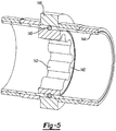
- FIGS. 4 and 5 depict an alternate pump identified at reference numeral 120.
- Pump 120 is also an integrated electric oil pump that is fully submersible within a fluid to be pumped.
- Integrated electric oil pump 120 includes a cylindrically shaped body 122, a first side plate 124 and a second side plate 126.
- First and second covers 128, 130 sealingly engage first and second side plates 124, 126.
- An inner rotor 132 includes a hub 134 supported for rotation by a bushing 136 positioned within a cavity 138 formed in second cover 130. Inner rotor 132 rotates about an axis of rotation 140.
- An outer rotor 142 includes internal lobes 143 in meshed engagement with external lobes (not shown) formed on inner rotor 132 to define a gerotor pump as previously described. Outer rotor 142 rotates about an axis of rotation offset from axis 140.
- a shaft 144 is fixed for rotation with outer rotor 142 via a plurality of balls 145.
- a plurality of permanent magnets 146 are fixed for rotation with shaft 144.
- Bearing rings 148 and 150 are also fixed for rotation with shaft 144.
- a bearing assembly 152 is mounted to first side plate 124 to rotatably support bearing ring 148.
- another bearing assembly 154 is coupled to second side plate 126 to rotatably support bearing ring 150, shaft 144 and outer rotor 142.
- First cover 128 includes a pump face 162 spaced apart from inner rotor 132 and outer rotor 142.
- a second pump surface 164 is formed at an end of second cover 130. Second pump surface 164 is spaced apart a predetermined distance from first pump surface 162 to provide a desired running clearance to inner rotor 132 and outer rotor 142.
- a stator 166 is positioned within a cavity 168 defined by body 122, first side plate 124 and second side plate 126.
- a ledge 169 is formed at an inner diameter of body 122 to locate and support stator 166.
- Stator 166 surrounds magnets 146 as previously described in relation to pump 10.
- a lip seal 170 is coupled to first side plate 124 and sealingly engages a seal plate 172 fixed for rotation with shaft 144.
- Another lip seal 174 is coupled to second side plate 126 and engages another seal ring 176 fixed for rotation with shaft 144.
- O-rings 178, 179 seal the joints between first side plate 124, second side plate 126 and body 122.
- An inlet port 180 is formed in second side plate 126.
- a strainer 182 allows fluid to pass therethrough but restricts entry of contaminants into the pump.
- a plurality of stands 184 extend from second cover 130 to space apart strainer 182 from a bottom of a sump containing the fluid to be pumped.
- Pump 120 is a sealed design where the fluid to be pumped and the fluid surrounding the pump is restricted from entry into cavity 168.
- FIG. 6 depicts another submersible pump identified at reference numeral 190.
- Pump 190 is substantially similar to pump 120. Accordingly, similar elements will be identified with like numerals including a prime suffix. Pump 190 differs from pump 120 in that stator 166 is not sealed from the fluid to be pumped. On the contrary, cavity 168' is filled with oil when pump 190 is submerged within the fluid.
- a plurality of apertures 192 are formed in first side plate 124' to allow entry and exit of fluid.
- a plurality of apertures 194 are formed in second side plate 126' to allow fluid communication with cavity 168'. Because sealing is no longer required, o-rings 178, 179 have been removed from pump 190. Furthermore, lip seals 170, 174, as well as seal rings 172 and 176 are no longer necessary. Associated machining of pockets or grooves to retain the seals is also not required even though the drawings may depict the presence of these features.
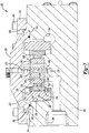
- Pump 200 is also configured as a submerged integrated electric oil pump.
- Pump 200 includes a housing 202 having a side wall 210.
- a recess 214 is defined by a substantially cylindrical wall 216.
- Threaded apertures 218 are circumferentially spaced apart from one another.
- Pump 200 includes a stator 222 positioned within cavity a 208.
- Side wall 210 is sized to closely fit an outer surface 224 of stator 222 to restrict stator 222 from radial movement.
- a land 226 is formed on housing 202 to partially define cavity 208 and provide a seat for a surface 228 of stator 222 to restrict axial movement of the stator relative to housing 202.
- a magnet ring 232 includes a substantially cylindrical portion 234 and a radially inwardly protruding portion 236. Magnet ring 232 includes a metallic backing ring portion and a plurality of magnets formed as one component. An outer substantially cylindrical surface 238 is spaced apart from an inner substantially cylindrical surface 240 of stator 222. An outer rotor 242 is fixed to magnet ring 232. A seat 246 and a substantially cylindrical wall 248 are sized to clear the outer dimensions of outer rotor 242 but be closely positioned to the outer rotor to maintain a desired radial and axial position of outer rotor 242.
- a cover 250 is fixed to housing 202 by a clamp ring 252 and fasteners 254.
- Cover 250 also defines a substantially planar surface 256 and a substantially cylindrical surface 258 that maintain the position of outer rotor 242.
- the alignment of cylindrical surfaces 258 and 248 is achieved by closely sizing an outer cylindrical surface 262 of cover 250 with cylindrical wall 216.
- An inner rotor 266 drivingly mates with outer rotor in similar fashion to that previously described with reference to rotor 22 and rotor 24.
- Inner rotor 266 is fixed to a center shaft 268.
- Inner rotor 266 and center shaft 268 are configured to rotate as a singular unit relative to housing 202 and cover 250.
- a bore 270 formed in housing 202 and a bore 272 formed in cover 250 receive ends of center shaft 268 and define its axis of rotation. Face 256 and seat 246 limit axial translation of inner rotor 266.
- Figure 9 depicts a dowel 280 positioned to assure accurate alignment and indexing of cover 250 relative to housing 202.
- a seal 282 is positioned within a groove 290 formed in cover 250 and engages recess 214.
- FIGS 10 and 11 depict a portion of an alternate pump identified at reference numeral 350.
- Pump 350 is substantially similar to pump 200 with the exception of a ring-shaped controller 352 being positioned adjacent stator 222.
- Controller 352 includes a board 354 positioned in engagement with stator 222.
- a number of electronic components including an integrated circuit 356, a capacitor 358 and a microprocessor 360 are fixed to board 354.
- Controller 352 is operable to control operation of pump 350.
- Board 354 and the components coupled thereto may be in communication with the fluid in which pump 350 is submersed. Based on the properties of the fluid to be pumped, controller 352 will function properly regardless of exposure to the fluid.
- a central aperture 362 extends through board 354. Central aperture 362 is sized and positioned to allow inner rotor 266 and outer rotor 242 to pass therethrough.
- Controller 352 may include an integrated circuit or integrated circuits operable to determine the current being provided to stator 222. Also, controller 352 may be operable to determine the torque applied to outer rotor 242.
- pump 350 receives current from an external source. Energy is provided to controller 352 where a determination is made whether to provide current to stator 222. The magnitude of current to be provided to stator 222 is also determined. As the magnitude of current provided to stator 222 varies, the strength of the electromagnetic field surrounding stator 222 is also varied. The electromagnetic field interacts with magnet ring 232 causing outer rotor 242 to rotate. Because outer rotor 242 is in meshed engagement with inner rotor 266, the inner rotor 266 is also forced to rotate. Rotation of inner rotor 266 and outer rotor 242 causes a fluid pumping action.
Landscapes
- Engineering & Computer Science (AREA)
- Mechanical Engineering (AREA)
- General Engineering & Computer Science (AREA)
- Power Engineering (AREA)
- Physics & Mathematics (AREA)
- Chemical & Material Sciences (AREA)
- Combustion & Propulsion (AREA)
- Electromagnetism (AREA)
- Connection Of Motors, Electrical Generators, Mechanical Devices, And The Like (AREA)
- Structures Of Non-Positive Displacement Pumps (AREA)
- Rotary Pumps (AREA)
- Details And Applications Of Rotary Liquid Pumps (AREA)
Claims (12)
- Unterwasserelektopumpe (200), umfassend:ein erstes Gehäuseelement (250) mit einer ersten Vertiefung, die eine im Wesentlichen ebene und von einer ersten Wand (258) umgebene erste Pumpenfläche (256) aufweist;ein zweites Gehäuseelement (202), das am ersten Gehäuseelement befestigt ist und eine zweite Vertiefung mit einer im Wesentlichen ebenen und von einer zweiten Wand (248) umgebenen zweiten Pumpenfläche (246) umfasst und im Wesentlichen parallel zur ersten Pumpenfläche (256) verläuft;eine Rotorpumpe mit einem innenverzahnten Rotor (266) und einem außenverzahnten Rotor (242), wobei jeder Rotor (266, 242) gegenüberliegende Seiten aufweist, die angrenzend an die erste und zweite Pumpenfläche (256, 246) angeordnet sind, wobei der außenverzahnte Rotor (242) innerhalb der ersten und zweiten Vertiefungen angeordnet und durch die erste und zweite Wand (258, 248) auf der Rotationsachse ausgerichtet ist;eine Rotorwelle (268), die in das erste und zweite Gehäuseelement eingreift und im Verhältnis zur Rotationsachse des außenverzahnten Rotors einen Versatz zur Rotationsachse des innenverzahnten Rotors definiert;einen Elektromotorstator (222), der in einer im zweiten Gehäuseelement (202) ausgebildeten Vertiefung (208) angeordnet ist; undeine Vielzahl von am außenverzahnten Rotor (242) befestigten Permanentmagneten, damit sich diese mit dem Rotor drehen, wobei die Magnete in der Nähe des Stators angeordnet sind.
- Elektropumpe (200) gemäß Anspruch 1, wobei die Rotorwelle (268) am innenverzahnten Rotor (266) befestigt ist, damit sie sich mit diesem dreht.
- Elektropumpe (200) gemäß Anspruch 2, wobei der Stator (222) in einen Steg (226) und eine Seitenwand (210) des zweiten Gehäuseelements (202) eingreift.
- Elektropumpe (200) gemäß Anspruch 1, ferner umfassend einem Magnetring (232), mit einem am außenverzahnten Rotor (242) befestigten sich radial erstreckenden Abschnitt (236), wobei die Magnete am Magnetring (232) befestigt sind.
- Elektropumpe (200) gemäß Anspruch 4, wobei der Magnetring (232) einen zylindrisch geformten Abschnitt (234) aufweist, der einen sich radial erstreckenden Abschnitt (236) umgibt und dadurch einen T-förmigen Querschnitt definiert.
- Elektropumpe (200) gemäß Anspruch 1 ferner umfassend eine Motorsteuerung (352), die mit dem Stator (222) gekoppelt ist.
- Elektropumpe (200) gemäß Anspruch 6, wobei die Motorsteuerung (352) eine zylindrisch geformte Platte (354) mit darauf angebrachten elektronischen Komponenten aufweist, wobei die Platte (354) eine durchgehende Öffnung (362) aufweist, in der sich der innenverzahnte Rotor (266) und der außenverzahnte Rotor (242) bewegen können.
- Elektropumpe (200) gemäß Anspruch 1, wobei entweder das erste oder zweite Gehäuseelement (250, 202) durchgehende Öffnungen aufweist und der Stator (222) dafür ausgelegt ist, mit dem Fluid in Kontakt zu sein, in das die Pumpe eingetaucht ist.
- Elektropumpe (200) gemäß Anspruch 1, wobei der Abstand zwischen den Permanentmagneten und einem stromführenden Element des Stators (222) zwischen 0,5 bis 0,8 mm liegt.
- Elektropumpe (200) gemäß Anspruch 1, wobei sich der innenverzahnte Rotor (266) und der außenverzahnte Rotor (242) jeweils um voneinander beabstandete Achsen rotieren, die sich im Wesentlichen parallel zueinander erstrecken.
- Elektropumpe (200) gemäß Anspruch 1, wobei der Stator (222) eine Drahtwicklung aufweist, die mit dem zu pumpenden Fluid in Kontakt ist.
- Elektropumpe (200) gemäß Anspruch 1, wobei der innenverzahnte und außenverzahnte Rotor (242, 266) Metallpulver enthalten.
Applications Claiming Priority (2)
| Application Number | Priority Date | Filing Date | Title |
|---|---|---|---|
| US11223108P | 2008-11-07 | 2008-11-07 | |
| PCT/CA2009/001614 WO2010051640A1 (en) | 2008-11-07 | 2009-11-05 | Fully submerged integrated electric oil pump |
Publications (3)
| Publication Number | Publication Date |
|---|---|
| EP2379892A1 EP2379892A1 (de) | 2011-10-26 |
| EP2379892A4 EP2379892A4 (de) | 2016-03-09 |
| EP2379892B1 true EP2379892B1 (de) | 2018-05-16 |
Family
ID=42152433
Family Applications (1)
| Application Number | Title | Priority Date | Filing Date |
|---|---|---|---|
| EP09824319.9A Active EP2379892B1 (de) | 2008-11-07 | 2009-11-05 | Vollständig untertauchbare integrierte elektroölpumpe |
Country Status (9)
| Country | Link |
|---|---|
| US (2) | US8632321B2 (de) |
| EP (1) | EP2379892B1 (de) |
| JP (1) | JP5615826B2 (de) |
| KR (2) | KR101719464B1 (de) |
| CN (1) | CN102203422B (de) |
| BR (1) | BRPI0922108A2 (de) |
| CA (1) | CA2742148C (de) |
| RU (1) | RU2517641C2 (de) |
| WO (1) | WO2010051640A1 (de) |
Cited By (1)
| Publication number | Priority date | Publication date | Assignee | Title |
|---|---|---|---|---|
| EP4375510A4 (de) * | 2021-07-19 | 2025-07-23 | Hangzhou Ao Ke Mei Rui Tech Co Ltd | Fluidantriebsvorrichtung |
Families Citing this family (24)
| Publication number | Priority date | Publication date | Assignee | Title |
|---|---|---|---|---|
| CN102459844A (zh) | 2009-06-09 | 2012-05-16 | 麦格纳动力系有限公司 | 双动力输入流体泵 |
| JP5564974B2 (ja) * | 2009-12-01 | 2014-08-06 | 株式会社ジェイテクト | 電動ポンプ及び電動ポンプの取付け構造 |
| KR101698914B1 (ko) * | 2010-10-05 | 2017-01-23 | 마그나 파워트레인 인크. | 이중 배출 펌프 |
| US9145865B2 (en) | 2012-06-29 | 2015-09-29 | General Electric Company | Electric fluid pump |
| US9624929B2 (en) * | 2012-12-21 | 2017-04-18 | Lg Innotek Co., Ltd. | Electric pump |
| US9601951B2 (en) | 2013-11-04 | 2017-03-21 | General Electric Company | Modular permanent magnet motor and pump assembly |
| CN105322730B (zh) * | 2014-07-28 | 2017-09-15 | 江门市地尔汉宇电器股份有限公司 | 一种永磁同步电机及其制备方法 |
| US10291091B2 (en) | 2014-09-25 | 2019-05-14 | Magna Powertrain Fpc Limited Partnership | Electric fluid pump with improved rotor unit, rotor unit therefor and methods of construction thereof |
| ITUA20163309A1 (it) * | 2016-05-10 | 2017-11-10 | Bosch Gmbh Robert | Gruppo di pompaggio per alimentare combustibile, preferibilmente gasolio, ad un motore a combustione interna |
| US10514035B2 (en) | 2016-05-16 | 2019-12-24 | Schaeffler Technologies AG & Co. KG | Integrated eccentric motor and pump |
| DE112017004001T5 (de) * | 2016-08-09 | 2019-04-18 | Nidec Corporation | Antriebsvorrichtung |
| US11035360B2 (en) | 2018-02-14 | 2021-06-15 | Stackpole International Engineered Products, Ltd. | Gerotor with spindle |
| US10989191B2 (en) | 2018-03-28 | 2021-04-27 | Schaeffler Technologies AG & Co. KG | Integrated motor and pump including radially movable outer gerator |
| US20190301453A1 (en) * | 2018-03-29 | 2019-10-03 | Schaeffler Technologies AG & Co. KG | Integrated motor and pump including inlet and outlet fluid control sections |
| US10927833B2 (en) | 2018-05-15 | 2021-02-23 | Schaeffler Technologies AG & Co. KG | Integrated eccentric motor and pump assembly |
| CN110857689B (zh) * | 2018-08-24 | 2021-10-19 | 杭州三花研究院有限公司 | 电动泵 |
| DE102019200560B4 (de) | 2018-09-14 | 2025-04-30 | Hanon Systems Efp Deutschland Gmbh | Gerotorpumpe und Verfahren zur Herstellung eines Druckausgleichs in einer Gerotorpumpe |
| KR20250108126A (ko) * | 2018-11-13 | 2025-07-15 | 지에이치에스피, 아이엔씨. | 다양한 적용에서 사용하기 위한 모듈식 유체 펌프 |
| US20200191143A1 (en) * | 2018-12-17 | 2020-06-18 | Charles H. Tuckey | Gerotor pump or motor device with rolling support |
| US11168690B2 (en) | 2019-04-11 | 2021-11-09 | Schaeffler Technologies AG & Co. KG | Integrated motor and pump including axially placed coils |
| DE102020129312A1 (de) * | 2019-12-02 | 2021-06-02 | Fte Automotive Gmbh | Flüssigkeitspumpe, insbesondere zur Versorgung eines Getriebes eines Elektro- oder Hybridantriebsmoduls eines Kraftfahrzeugs |
| US11990819B2 (en) | 2020-11-24 | 2024-05-21 | Bosch Rexroth Corporation | Electric and hydraulic machine |
| EP4267858B8 (de) * | 2020-12-28 | 2026-02-25 | O.M.P. Officine Mazzocco Pagnoni S.r.l. | Ölpumpe für kraftfahrzeug |
| US11680565B2 (en) | 2021-02-08 | 2023-06-20 | Schaeffler Technologies AG & Co. KG | Motor-pump system |
Family Cites Families (64)
| Publication number | Priority date | Publication date | Assignee | Title |
|---|---|---|---|---|
| US1966A (en) * | 1841-02-03 | Manner of forming blocks of wood for paving streets | ||
| US1531724A (en) * | 1921-04-18 | 1925-03-31 | Arutunoff Armais | Electric machine |
| US2711286A (en) * | 1952-08-01 | 1955-06-21 | Wetmore Hodges | Motor-pump or compressor |
| US2871793A (en) * | 1956-06-29 | 1959-02-03 | Robbins & Myers | Electric motor and pump combination |
| BE646788A (de) * | 1963-04-20 | |||
| GB1024874A (en) * | 1963-10-04 | 1966-04-06 | Birmingham Small Arms Co Ltd | Improvements in or relating to rotary piston internal combustion engines |
| US4519755A (en) | 1980-05-09 | 1985-05-28 | Sargent-Welch Scientific Company | Gerotor vacuum pump |
| JPS6081488A (ja) * | 1983-10-13 | 1985-05-09 | Honda Motor Co Ltd | ポンプ装置 |
| JPS60149892U (ja) * | 1983-11-29 | 1985-10-04 | 本田技研工業株式会社 | 液体圧送用ポンプ装置 |
| US4749894A (en) * | 1985-03-11 | 1988-06-07 | Ebara Corporation | Submersible motor using a water-tight wire as the primary winding |
| US5034638A (en) * | 1990-03-14 | 1991-07-23 | Westinghouse Electric Corp. | Generator auxiliary mode lubrication system and method |
| US5219277A (en) * | 1990-05-29 | 1993-06-15 | Walbro Corporation | Electric-motor fuel pump |
| US5145329A (en) * | 1990-06-29 | 1992-09-08 | Eaton Corporation | Homoplanar brushless electric gerotor |
| DE4102162A1 (de) * | 1991-01-25 | 1992-07-30 | Bosch Gmbh Robert | Vorrichtung zum foerdern von kraftstoff aus einem vorratstank zur brennkraftmaschine eines kraftfahrzeuges |
| IT1245466B (it) * | 1991-03-19 | 1994-09-20 | Iveco Fiat | Elettropompa per la circolazione di un liquido, ad esempio in un motore a combustione interna |
| US5145348A (en) | 1991-05-15 | 1992-09-08 | Eaton Corporation | Gerotor pump having an improved drive mechanism |
| DE4120665A1 (de) | 1991-06-22 | 1992-12-24 | Teves Gmbh Alfred | Elektromotorisch angetriebene hydraulikpumpe |
| US5190447A (en) * | 1992-03-23 | 1993-03-02 | The United States Of America As Represented By The Secretary Of The Navy | Hydraulic pump with integral electric motor |
| US5217085A (en) | 1992-05-04 | 1993-06-08 | Ford Motor Company | Lubrication and cooling system for a powertrain including an electric motor |
| US5336064A (en) | 1993-12-06 | 1994-08-09 | Westinghouse Electric Corporation | Electric motor driven pump |
| EP0679808B1 (de) | 1994-04-26 | 1999-10-13 | LuK Fahrzeug-Hydraulik GmbH & Co. KG | Flügelzellenpumpe |
| US5509792A (en) * | 1995-02-27 | 1996-04-23 | Pumpworks, Inc. | Electromagnetically driven reciprocating pump with fluted piston |
| EP0758716B1 (de) | 1995-08-14 | 2003-12-10 | LuK Fahrzeug-Hydraulik GmbH & Co. KG | Flügelzellenpumpe |
| US5743231A (en) | 1996-03-01 | 1998-04-28 | Reinosa; Adan | Automatic method and apparatus for preventing wear in an internal combustion engine |
| EP0906512B1 (de) | 1996-06-21 | 2002-10-23 | LuK Fahrzeug-Hydraulik GmbH & Co. KG | Flügelzellenpumpe |
| DE19626211C2 (de) | 1996-06-29 | 2002-03-14 | Luk Fahrzeug Hydraulik | Flügelzellenpumpe |
| EP0851123B1 (de) | 1996-12-23 | 2003-07-09 | LuK Fahrzeug-Hydraulik GmbH & Co. KG | Flügelzellenmaschine, insbesondere Flügelzellenpumpe |
| US6349692B1 (en) | 1997-02-26 | 2002-02-26 | Adan Reinosa | Method and apparatus for reducing wear in an internal combustion engine |
| IT1299077B1 (it) | 1997-04-16 | 2000-02-07 | Luk Fahrzeug Hydraulik | Pompa rotativa a palette |
| USH1966H1 (en) * | 1997-08-28 | 2001-06-05 | The United States Of America As Represented By The Secretary Of The Navy | Integrated motor/gear pump |
| DE19846815B4 (de) | 1997-10-16 | 2014-08-07 | Ixetic Bad Homburg Gmbh | Ventilanordnung und Pumpe für ein Getriebe |
| US5923111A (en) * | 1997-11-10 | 1999-07-13 | Goulds Pumps, Incoporated | Modular permanent-magnet electric motor |
| DE19802443C1 (de) | 1998-01-23 | 1999-05-12 | Luk Fahrzeug Hydraulik | Pumpe |
| DE19900926B4 (de) | 1998-01-28 | 2015-01-22 | Magna Powertrain Bad Homburg GmbH | Pumpe |
| JP3972465B2 (ja) * | 1998-05-29 | 2007-09-05 | 株式会社デンソー | 電動ポンプ |
| DE19927400A1 (de) | 1998-06-24 | 1999-12-30 | Luk Fahrzeug Hydraulik | Hydraulische Fördereinrichtung |
| WO2000009887A2 (de) | 1998-08-13 | 2000-02-24 | Luk Fahrzeug-Hydraulik Gmbh & Co. Kg | Pumpe |
| GB9913584D0 (en) | 1998-10-12 | 1999-08-11 | S U Automotive Limited | Improvements in or relating to a pumping apparatus |
| KR100425375B1 (ko) * | 1998-11-28 | 2004-06-16 | 레슬리 머빈 해리슨 | 유체베인모터/펌프 |
| US6879078B2 (en) * | 2000-01-12 | 2005-04-12 | Neodrive Llc | Electric motor with external rotor |
| US6896489B2 (en) | 2000-12-12 | 2005-05-24 | Borgwarner Inc. | Variable displacement vane pump with variable target regulator |
| US6579013B2 (en) | 2001-03-15 | 2003-06-17 | Jds Uniphase Corporation | Optical fiber coupler and an optical fiber coupler incorporated within a transceiver module |
| FR2829535B1 (fr) | 2001-09-12 | 2005-08-12 | Pierburg | Pompe a palettes a cylindree variable |
| US7174998B2 (en) * | 2001-10-15 | 2007-02-13 | Borgwarner Inc. | Submerged electric fluid pump |
| JP2003269345A (ja) * | 2002-03-13 | 2003-09-25 | Aisin Seiki Co Ltd | 電動オイルポンプ |
| EP1350930B2 (de) | 2002-04-03 | 2016-01-27 | SLW Automotive Inc. | Regelbare Verdrängerpump sowie Steursystem dafür |
| US6888273B2 (en) * | 2002-10-31 | 2005-05-03 | Eaton Corporation | Integrated motor and clutch assembly |
| US20040101427A1 (en) * | 2002-11-27 | 2004-05-27 | Visteon Global Technologies Inc. | Gerotor fuel pump having primary and secondary inlet and outlet portings |
| WO2004059821A1 (ja) * | 2002-12-26 | 2004-07-15 | Iai Corporation | 駆動装置 |
| ITBO20030528A1 (it) | 2003-09-12 | 2005-03-13 | Pierburg Spa | Impianto di pompaggio utilizzante una pompa a palette |
| DE10349752B4 (de) * | 2003-10-24 | 2006-04-06 | Voith Turbo Gmbh & Co. Kg | Motorpumpenaggregat |
| ITBO20040008A1 (it) | 2004-01-09 | 2004-04-09 | Pierburg Spa | Impianto di pompaggio |
| KR100704160B1 (ko) * | 2004-02-09 | 2007-04-06 | (주)프로닉스 | 플라즈마 발생장치 및 플라즈마 발생 연결관 |
| JP2005273648A (ja) * | 2004-02-23 | 2005-10-06 | Aisin Seiki Co Ltd | 電動ポンプ |
| US7352090B2 (en) * | 2004-03-19 | 2008-04-01 | Hamilton Sundstrand | Fluid-submerged electric motor |
| US7137793B2 (en) * | 2004-04-05 | 2006-11-21 | Peopleflo Manufacturing, Inc. | Magnetically driven gear pump |
| JP4786203B2 (ja) * | 2005-03-08 | 2011-10-05 | 株式会社ダイヤメット | 内接型ギヤポンプ |
| JP4237731B2 (ja) * | 2005-05-31 | 2009-03-11 | 株式会社日立製作所 | モータ一体型内接歯車式ポンプ及びその製造方法並びに電子機器 |
| JP2007120465A (ja) * | 2005-10-31 | 2007-05-17 | Sumitomo Denko Shoketsu Gokin Kk | ポンプロータとそれを用いた内接歯車式ポンプ |
| US7641457B2 (en) * | 2006-03-28 | 2010-01-05 | Jtekt Corporation | Internal gear pump |
| US20080019846A1 (en) * | 2006-03-31 | 2008-01-24 | White Stephen L | Variable displacement gerotor pump |
| JP2008086064A (ja) * | 2006-09-26 | 2008-04-10 | Jtekt Corp | ブラシレスモータ |
| JP2009287463A (ja) * | 2008-05-29 | 2009-12-10 | Aisin Ai Co Ltd | ポンプ |
| JP5577584B2 (ja) * | 2008-11-07 | 2014-08-27 | 株式会社ジェイテクト | 電動ポンプユニット |
-
2009
- 2009-11-05 CA CA2742148A patent/CA2742148C/en active Active
- 2009-11-05 EP EP09824319.9A patent/EP2379892B1/de active Active
- 2009-11-05 RU RU2011122725/06A patent/RU2517641C2/ru not_active IP Right Cessation
- 2009-11-05 WO PCT/CA2009/001614 patent/WO2010051640A1/en not_active Ceased
- 2009-11-05 KR KR1020167030114A patent/KR101719464B1/ko active Active
- 2009-11-05 US US12/612,892 patent/US8632321B2/en active Active
- 2009-11-05 CN CN200980144103.2A patent/CN102203422B/zh active Active
- 2009-11-05 JP JP2011534982A patent/JP5615826B2/ja active Active
- 2009-11-05 KR KR1020117010385A patent/KR101689407B1/ko active Active
- 2009-11-05 BR BRPI0922108A patent/BRPI0922108A2/pt not_active IP Right Cessation
-
2014
- 2014-01-08 US US14/150,191 patent/US9581158B2/en active Active
Non-Patent Citations (1)
| Title |
|---|
| None * |
Cited By (1)
| Publication number | Priority date | Publication date | Assignee | Title |
|---|---|---|---|---|
| EP4375510A4 (de) * | 2021-07-19 | 2025-07-23 | Hangzhou Ao Ke Mei Rui Tech Co Ltd | Fluidantriebsvorrichtung |
Also Published As
| Publication number | Publication date |
|---|---|
| CA2742148C (en) | 2017-05-30 |
| RU2011122725A (ru) | 2012-12-20 |
| US20100129239A1 (en) | 2010-05-27 |
| KR101689407B1 (ko) | 2016-12-23 |
| KR20160128457A (ko) | 2016-11-07 |
| CA2742148A1 (en) | 2010-05-14 |
| JP5615826B2 (ja) | 2014-10-29 |
| KR20110084904A (ko) | 2011-07-26 |
| EP2379892A4 (de) | 2016-03-09 |
| JP2012508344A (ja) | 2012-04-05 |
| WO2010051640A1 (en) | 2010-05-14 |
| US20140119963A1 (en) | 2014-05-01 |
| CN102203422A (zh) | 2011-09-28 |
| EP2379892A1 (de) | 2011-10-26 |
| RU2517641C2 (ru) | 2014-05-27 |
| KR101719464B1 (ko) | 2017-03-23 |
| US8632321B2 (en) | 2014-01-21 |
| US9581158B2 (en) | 2017-02-28 |
| CN102203422B (zh) | 2014-04-02 |
| BRPI0922108A2 (pt) | 2016-06-21 |
Similar Documents
| Publication | Publication Date | Title |
|---|---|---|
| EP2379892B1 (de) | Vollständig untertauchbare integrierte elektroölpumpe | |
| JP2012508344A6 (ja) | 完全サブマージド一体形電気オイルポンプ | |
| CA2753510C (en) | Integrated electric vane oil pump | |
| JP4653125B2 (ja) | リニア圧縮機 | |
| US7986068B2 (en) | Motor | |
| US6078121A (en) | Rotor assembly for a rotating machine | |
| US6025665A (en) | Rotating machine for use in a pressurized fluid system | |
| CN107923389B (zh) | 电动泵及其制造方法 | |
| US10954944B2 (en) | Compressor having counterweight assembly | |
| GB2417981A (en) | Sealing arrangement for a canned motor pump | |
| CN110120715B (zh) | 可变磁场旋转电机以及具备该可变磁场旋转电机的车辆 | |
| JP5343480B2 (ja) | 油圧界磁制御回転電機 | |
| JP6509524B2 (ja) | モータロータおよびそれを用いたモータ並びに電動圧縮機 | |
| KR20260005611A (ko) | 로터 및 이를 포함하는 전동 압축기 |
Legal Events
| Date | Code | Title | Description |
|---|---|---|---|
| PUAI | Public reference made under article 153(3) epc to a published international application that has entered the european phase |
Free format text: ORIGINAL CODE: 0009012 |
|
| 17P | Request for examination filed |
Effective date: 20110912 |
|
| AK | Designated contracting states |
Kind code of ref document: A1 Designated state(s): AT BE BG CH CY CZ DE DK EE ES FI FR GB GR HR HU IE IS IT LI LT LU LV MC MK MT NL NO PL PT RO SE SI SK SM TR |
|
| DAX | Request for extension of the european patent (deleted) | ||
| RIN1 | Information on inventor provided before grant (corrected) |
Inventor name: HADAR, GIL Inventor name: BENNETT, ANDY |
|
| RIC1 | Information provided on ipc code assigned before grant |
Ipc: H02K 7/14 20060101ALI20160127BHEP Ipc: F04C 11/00 20060101ALI20160127BHEP Ipc: F04C 15/00 20060101ALI20160127BHEP Ipc: F04C 2/10 20060101AFI20160127BHEP |
|
| RA4 | Supplementary search report drawn up and despatched (corrected) |
Effective date: 20160209 |
|
| RIC1 | Information provided on ipc code assigned before grant |
Ipc: F04C 11/00 20060101ALI20160202BHEP Ipc: H02K 7/14 20060101ALI20160202BHEP Ipc: F04C 2/10 20060101AFI20160202BHEP Ipc: F04C 15/00 20060101ALI20160202BHEP |
|
| GRAP | Despatch of communication of intention to grant a patent |
Free format text: ORIGINAL CODE: EPIDOSNIGR1 |
|
| STAA | Information on the status of an ep patent application or granted ep patent |
Free format text: STATUS: GRANT OF PATENT IS INTENDED |
|
| INTG | Intention to grant announced |
Effective date: 20171129 |
|
| GRAS | Grant fee paid |
Free format text: ORIGINAL CODE: EPIDOSNIGR3 |
|
| GRAA | (expected) grant |
Free format text: ORIGINAL CODE: 0009210 |
|
| STAA | Information on the status of an ep patent application or granted ep patent |
Free format text: STATUS: THE PATENT HAS BEEN GRANTED |
|
| AK | Designated contracting states |
Kind code of ref document: B1 Designated state(s): AT BE BG CH CY CZ DE DK EE ES FI FR GB GR HR HU IE IS IT LI LT LU LV MC MK MT NL NO PL PT RO SE SI SK SM TR |
|
| REG | Reference to a national code |
Ref country code: GB Ref legal event code: FG4D |
|
| REG | Reference to a national code |
Ref country code: CH Ref legal event code: EP |
|
| REG | Reference to a national code |
Ref country code: IE Ref legal event code: FG4D |
|
| REG | Reference to a national code |
Ref country code: DE Ref legal event code: R096 Ref document number: 602009052367 Country of ref document: DE |
|
| REG | Reference to a national code |
Ref country code: AT Ref legal event code: REF Ref document number: 999845 Country of ref document: AT Kind code of ref document: T Effective date: 20180615 |
|
| REG | Reference to a national code |
Ref country code: NL Ref legal event code: MP Effective date: 20180516 |
|
| REG | Reference to a national code |
Ref country code: LT Ref legal event code: MG4D |
|
| PG25 | Lapsed in a contracting state [announced via postgrant information from national office to epo] |
Ref country code: SE Free format text: LAPSE BECAUSE OF FAILURE TO SUBMIT A TRANSLATION OF THE DESCRIPTION OR TO PAY THE FEE WITHIN THE PRESCRIBED TIME-LIMIT Effective date: 20180516 Ref country code: ES Free format text: LAPSE BECAUSE OF FAILURE TO SUBMIT A TRANSLATION OF THE DESCRIPTION OR TO PAY THE FEE WITHIN THE PRESCRIBED TIME-LIMIT Effective date: 20180516 Ref country code: LT Free format text: LAPSE BECAUSE OF FAILURE TO SUBMIT A TRANSLATION OF THE DESCRIPTION OR TO PAY THE FEE WITHIN THE PRESCRIBED TIME-LIMIT Effective date: 20180516 Ref country code: BG Free format text: LAPSE BECAUSE OF FAILURE TO SUBMIT A TRANSLATION OF THE DESCRIPTION OR TO PAY THE FEE WITHIN THE PRESCRIBED TIME-LIMIT Effective date: 20180816 Ref country code: NO Free format text: LAPSE BECAUSE OF FAILURE TO SUBMIT A TRANSLATION OF THE DESCRIPTION OR TO PAY THE FEE WITHIN THE PRESCRIBED TIME-LIMIT Effective date: 20180816 Ref country code: FI Free format text: LAPSE BECAUSE OF FAILURE TO SUBMIT A TRANSLATION OF THE DESCRIPTION OR TO PAY THE FEE WITHIN THE PRESCRIBED TIME-LIMIT Effective date: 20180516 |
|
| PG25 | Lapsed in a contracting state [announced via postgrant information from national office to epo] |
Ref country code: GR Free format text: LAPSE BECAUSE OF FAILURE TO SUBMIT A TRANSLATION OF THE DESCRIPTION OR TO PAY THE FEE WITHIN THE PRESCRIBED TIME-LIMIT Effective date: 20180817 Ref country code: LV Free format text: LAPSE BECAUSE OF FAILURE TO SUBMIT A TRANSLATION OF THE DESCRIPTION OR TO PAY THE FEE WITHIN THE PRESCRIBED TIME-LIMIT Effective date: 20180516 Ref country code: NL Free format text: LAPSE BECAUSE OF FAILURE TO SUBMIT A TRANSLATION OF THE DESCRIPTION OR TO PAY THE FEE WITHIN THE PRESCRIBED TIME-LIMIT Effective date: 20180516 Ref country code: HR Free format text: LAPSE BECAUSE OF FAILURE TO SUBMIT A TRANSLATION OF THE DESCRIPTION OR TO PAY THE FEE WITHIN THE PRESCRIBED TIME-LIMIT Effective date: 20180516 |
|
| REG | Reference to a national code |
Ref country code: AT Ref legal event code: MK05 Ref document number: 999845 Country of ref document: AT Kind code of ref document: T Effective date: 20180516 |
|
| PG25 | Lapsed in a contracting state [announced via postgrant information from national office to epo] |
Ref country code: SK Free format text: LAPSE BECAUSE OF FAILURE TO SUBMIT A TRANSLATION OF THE DESCRIPTION OR TO PAY THE FEE WITHIN THE PRESCRIBED TIME-LIMIT Effective date: 20180516 Ref country code: PL Free format text: LAPSE BECAUSE OF FAILURE TO SUBMIT A TRANSLATION OF THE DESCRIPTION OR TO PAY THE FEE WITHIN THE PRESCRIBED TIME-LIMIT Effective date: 20180516 Ref country code: EE Free format text: LAPSE BECAUSE OF FAILURE TO SUBMIT A TRANSLATION OF THE DESCRIPTION OR TO PAY THE FEE WITHIN THE PRESCRIBED TIME-LIMIT Effective date: 20180516 Ref country code: DK Free format text: LAPSE BECAUSE OF FAILURE TO SUBMIT A TRANSLATION OF THE DESCRIPTION OR TO PAY THE FEE WITHIN THE PRESCRIBED TIME-LIMIT Effective date: 20180516 Ref country code: RO Free format text: LAPSE BECAUSE OF FAILURE TO SUBMIT A TRANSLATION OF THE DESCRIPTION OR TO PAY THE FEE WITHIN THE PRESCRIBED TIME-LIMIT Effective date: 20180516 Ref country code: AT Free format text: LAPSE BECAUSE OF FAILURE TO SUBMIT A TRANSLATION OF THE DESCRIPTION OR TO PAY THE FEE WITHIN THE PRESCRIBED TIME-LIMIT Effective date: 20180516 Ref country code: CZ Free format text: LAPSE BECAUSE OF FAILURE TO SUBMIT A TRANSLATION OF THE DESCRIPTION OR TO PAY THE FEE WITHIN THE PRESCRIBED TIME-LIMIT Effective date: 20180516 |
|
| REG | Reference to a national code |
Ref country code: DE Ref legal event code: R097 Ref document number: 602009052367 Country of ref document: DE |
|
| PG25 | Lapsed in a contracting state [announced via postgrant information from national office to epo] |
Ref country code: SM Free format text: LAPSE BECAUSE OF FAILURE TO SUBMIT A TRANSLATION OF THE DESCRIPTION OR TO PAY THE FEE WITHIN THE PRESCRIBED TIME-LIMIT Effective date: 20180516 Ref country code: IT Free format text: LAPSE BECAUSE OF FAILURE TO SUBMIT A TRANSLATION OF THE DESCRIPTION OR TO PAY THE FEE WITHIN THE PRESCRIBED TIME-LIMIT Effective date: 20180516 |
|
| PLBE | No opposition filed within time limit |
Free format text: ORIGINAL CODE: 0009261 |
|
| STAA | Information on the status of an ep patent application or granted ep patent |
Free format text: STATUS: NO OPPOSITION FILED WITHIN TIME LIMIT |
|
| 26N | No opposition filed |
Effective date: 20190219 |
|
| PG25 | Lapsed in a contracting state [announced via postgrant information from national office to epo] |
Ref country code: SI Free format text: LAPSE BECAUSE OF FAILURE TO SUBMIT A TRANSLATION OF THE DESCRIPTION OR TO PAY THE FEE WITHIN THE PRESCRIBED TIME-LIMIT Effective date: 20180516 |
|
| REG | Reference to a national code |
Ref country code: CH Ref legal event code: PL |
|
| GBPC | Gb: european patent ceased through non-payment of renewal fee |
Effective date: 20181105 |
|
| PG25 | Lapsed in a contracting state [announced via postgrant information from national office to epo] |
Ref country code: MC Free format text: LAPSE BECAUSE OF FAILURE TO SUBMIT A TRANSLATION OF THE DESCRIPTION OR TO PAY THE FEE WITHIN THE PRESCRIBED TIME-LIMIT Effective date: 20180516 Ref country code: LU Free format text: LAPSE BECAUSE OF NON-PAYMENT OF DUE FEES Effective date: 20181105 |
|
| REG | Reference to a national code |
Ref country code: BE Ref legal event code: MM Effective date: 20181130 |
|
| REG | Reference to a national code |
Ref country code: IE Ref legal event code: MM4A |
|
| PG25 | Lapsed in a contracting state [announced via postgrant information from national office to epo] |
Ref country code: LI Free format text: LAPSE BECAUSE OF NON-PAYMENT OF DUE FEES Effective date: 20181130 Ref country code: CH Free format text: LAPSE BECAUSE OF NON-PAYMENT OF DUE FEES Effective date: 20181130 |
|
| PG25 | Lapsed in a contracting state [announced via postgrant information from national office to epo] |
Ref country code: IE Free format text: LAPSE BECAUSE OF NON-PAYMENT OF DUE FEES Effective date: 20181105 Ref country code: FR Free format text: LAPSE BECAUSE OF NON-PAYMENT OF DUE FEES Effective date: 20181130 |
|
| PG25 | Lapsed in a contracting state [announced via postgrant information from national office to epo] |
Ref country code: BE Free format text: LAPSE BECAUSE OF NON-PAYMENT OF DUE FEES Effective date: 20181130 |
|
| PG25 | Lapsed in a contracting state [announced via postgrant information from national office to epo] |
Ref country code: GB Free format text: LAPSE BECAUSE OF NON-PAYMENT OF DUE FEES Effective date: 20181105 |
|
| PG25 | Lapsed in a contracting state [announced via postgrant information from national office to epo] |
Ref country code: MT Free format text: LAPSE BECAUSE OF NON-PAYMENT OF DUE FEES Effective date: 20181105 |
|
| PG25 | Lapsed in a contracting state [announced via postgrant information from national office to epo] |
Ref country code: TR Free format text: LAPSE BECAUSE OF FAILURE TO SUBMIT A TRANSLATION OF THE DESCRIPTION OR TO PAY THE FEE WITHIN THE PRESCRIBED TIME-LIMIT Effective date: 20180516 |
|
| PG25 | Lapsed in a contracting state [announced via postgrant information from national office to epo] |
Ref country code: PT Free format text: LAPSE BECAUSE OF FAILURE TO SUBMIT A TRANSLATION OF THE DESCRIPTION OR TO PAY THE FEE WITHIN THE PRESCRIBED TIME-LIMIT Effective date: 20180516 |
|
| PG25 | Lapsed in a contracting state [announced via postgrant information from national office to epo] |
Ref country code: MK Free format text: LAPSE BECAUSE OF NON-PAYMENT OF DUE FEES Effective date: 20180516 Ref country code: CY Free format text: LAPSE BECAUSE OF FAILURE TO SUBMIT A TRANSLATION OF THE DESCRIPTION OR TO PAY THE FEE WITHIN THE PRESCRIBED TIME-LIMIT Effective date: 20180516 Ref country code: HU Free format text: LAPSE BECAUSE OF FAILURE TO SUBMIT A TRANSLATION OF THE DESCRIPTION OR TO PAY THE FEE WITHIN THE PRESCRIBED TIME-LIMIT; INVALID AB INITIO Effective date: 20091105 |
|
| REG | Reference to a national code |
Ref country code: DE Ref legal event code: R082 Ref document number: 602009052367 Country of ref document: DE Representative=s name: HASELTINE LAKE KEMPNER LLP, DE Ref country code: DE Ref legal event code: R081 Ref document number: 602009052367 Country of ref document: DE Owner name: MAGNA POWERTRAIN FPC LIMITED PARTNERSHIP, AURO, CA Free format text: FORMER OWNER: STT TECHNOLOGIES INC., A JOINT VENTURE OF MAGNA POWERTRAIN INC. AND SHW GMBH, CONCORD, ONTARIO, CA Ref country code: DE Ref legal event code: R082 Ref document number: 602009052367 Country of ref document: DE Representative=s name: HL KEMPNER PATENTANWALT, RECHTSANWALT, SOLICIT, DE Ref country code: DE Ref legal event code: R081 Ref document number: 602009052367 Country of ref document: DE Owner name: HANON SYSTEMS EFP CANADA LTD., CONCORD, CA Free format text: FORMER OWNER: STT TECHNOLOGIES INC., A JOINT VENTURE OF MAGNA POWERTRAIN INC. AND SHW GMBH, CONCORD, ONTARIO, CA |
|
| PG25 | Lapsed in a contracting state [announced via postgrant information from national office to epo] |
Ref country code: IS Free format text: LAPSE BECAUSE OF FAILURE TO SUBMIT A TRANSLATION OF THE DESCRIPTION OR TO PAY THE FEE WITHIN THE PRESCRIBED TIME-LIMIT Effective date: 20180916 |
|
| REG | Reference to a national code |
Ref country code: DE Ref legal event code: R082 Ref document number: 602009052367 Country of ref document: DE Representative=s name: HL KEMPNER PATENTANWAELTE, SOLICITORS (ENGLAND, DE Ref country code: DE Ref legal event code: R082 Ref document number: 602009052367 Country of ref document: DE Representative=s name: HL KEMPNER PARTG MBB, DE Ref country code: DE Ref legal event code: R082 Ref document number: 602009052367 Country of ref document: DE Representative=s name: HL KEMPNER PATENTANWALT, RECHTSANWALT, SOLICIT, DE |
|
| REG | Reference to a national code |
Ref country code: DE Ref legal event code: R082 Ref document number: 602009052367 Country of ref document: DE Representative=s name: HL KEMPNER PATENTANWALT, RECHTSANWALT, SOLICIT, DE Ref country code: DE Ref legal event code: R081 Ref document number: 602009052367 Country of ref document: DE Owner name: HANON SYSTEMS EFP CANADA LTD., CONCORD, CA Free format text: FORMER OWNER: MAGNA POWERTRAIN FPC LIMITED PARTNERSHIP, AURORA, ONTARIO, CA |
|
| P01 | Opt-out of the competence of the unified patent court (upc) registered |
Effective date: 20230615 |
|
| PGFP | Annual fee paid to national office [announced via postgrant information from national office to epo] |
Ref country code: DE Payment date: 20250910 Year of fee payment: 17 |