EP2379906B1 - Profil de transmission de couples de rotation et liaison par couple de rotation - Google Patents
Profil de transmission de couples de rotation et liaison par couple de rotation Download PDFInfo
- Publication number
- EP2379906B1 EP2379906B1 EP09813827.4A EP09813827A EP2379906B1 EP 2379906 B1 EP2379906 B1 EP 2379906B1 EP 09813827 A EP09813827 A EP 09813827A EP 2379906 B1 EP2379906 B1 EP 2379906B1
- Authority
- EP
- European Patent Office
- Prior art keywords
- shaft
- journal
- external thread
- profile
- shank
- Prior art date
- Legal status (The legal status is an assumption and is not a legal conclusion. Google has not performed a legal analysis and makes no representation as to the accuracy of the status listed.)
- Active
Links
Images


Classifications
-
- F—MECHANICAL ENGINEERING; LIGHTING; HEATING; WEAPONS; BLASTING
- F16—ENGINEERING ELEMENTS AND UNITS; GENERAL MEASURES FOR PRODUCING AND MAINTAINING EFFECTIVE FUNCTIONING OF MACHINES OR INSTALLATIONS; THERMAL INSULATION IN GENERAL
- F16D—COUPLINGS FOR TRANSMITTING ROTATION; CLUTCHES; BRAKES
- F16D1/00—Couplings for rigidly connecting two coaxial shafts or other movable machine elements
- F16D1/10—Quick-acting couplings in which the parts are connected by simply bringing them together axially
-
- F—MECHANICAL ENGINEERING; LIGHTING; HEATING; WEAPONS; BLASTING
- F16—ENGINEERING ELEMENTS AND UNITS; GENERAL MEASURES FOR PRODUCING AND MAINTAINING EFFECTIVE FUNCTIONING OF MACHINES OR INSTALLATIONS; THERMAL INSULATION IN GENERAL
- F16B—DEVICES FOR FASTENING OR SECURING CONSTRUCTIONAL ELEMENTS OR MACHINE PARTS TOGETHER, e.g. NAILS, BOLTS, CIRCLIPS, CLAMPS, CLIPS OR WEDGES; JOINTS OR JOINTING
- F16B35/00—Screw-bolts; Stay-bolts; Screw-threaded studs; Screws; Set screws
- F16B35/04—Screw-bolts; Stay-bolts; Screw-threaded studs; Screws; Set screws with specially-shaped head or shaft in order to fix the bolt on or in an object
- F16B35/041—Specially-shaped shafts
-
- F—MECHANICAL ENGINEERING; LIGHTING; HEATING; WEAPONS; BLASTING
- F16—ENGINEERING ELEMENTS AND UNITS; GENERAL MEASURES FOR PRODUCING AND MAINTAINING EFFECTIVE FUNCTIONING OF MACHINES OR INSTALLATIONS; THERMAL INSULATION IN GENERAL
- F16B—DEVICES FOR FASTENING OR SECURING CONSTRUCTIONAL ELEMENTS OR MACHINE PARTS TOGETHER, e.g. NAILS, BOLTS, CIRCLIPS, CLAMPS, CLIPS OR WEDGES; JOINTS OR JOINTING
- F16B35/00—Screw-bolts; Stay-bolts; Screw-threaded studs; Screws; Set screws
- F16B35/04—Screw-bolts; Stay-bolts; Screw-threaded studs; Screws; Set screws with specially-shaped head or shaft in order to fix the bolt on or in an object
-
- F—MECHANICAL ENGINEERING; LIGHTING; HEATING; WEAPONS; BLASTING
- F16—ENGINEERING ELEMENTS AND UNITS; GENERAL MEASURES FOR PRODUCING AND MAINTAINING EFFECTIVE FUNCTIONING OF MACHINES OR INSTALLATIONS; THERMAL INSULATION IN GENERAL
- F16D—COUPLINGS FOR TRANSMITTING ROTATION; CLUTCHES; BRAKES
- F16D1/00—Couplings for rigidly connecting two coaxial shafts or other movable machine elements
- F16D1/10—Quick-acting couplings in which the parts are connected by simply bringing them together axially
- F16D1/101—Quick-acting couplings in which the parts are connected by simply bringing them together axially without axial retaining means rotating with the coupling
-
- F—MECHANICAL ENGINEERING; LIGHTING; HEATING; WEAPONS; BLASTING
- F16—ENGINEERING ELEMENTS AND UNITS; GENERAL MEASURES FOR PRODUCING AND MAINTAINING EFFECTIVE FUNCTIONING OF MACHINES OR INSTALLATIONS; THERMAL INSULATION IN GENERAL
- F16B—DEVICES FOR FASTENING OR SECURING CONSTRUCTIONAL ELEMENTS OR MACHINE PARTS TOGETHER, e.g. NAILS, BOLTS, CIRCLIPS, CLAMPS, CLIPS OR WEDGES; JOINTS OR JOINTING
- F16B2200/00—Constructional details of connections not covered for in other groups of this subclass
- F16B2200/69—Redundant disconnection blocking means
- F16B2200/73—Cam locks or thread locks
-
- F—MECHANICAL ENGINEERING; LIGHTING; HEATING; WEAPONS; BLASTING
- F16—ENGINEERING ELEMENTS AND UNITS; GENERAL MEASURES FOR PRODUCING AND MAINTAINING EFFECTIVE FUNCTIONING OF MACHINES OR INSTALLATIONS; THERMAL INSULATION IN GENERAL
- F16D—COUPLINGS FOR TRANSMITTING ROTATION; CLUTCHES; BRAKES
- F16D1/00—Couplings for rigidly connecting two coaxial shafts or other movable machine elements
- F16D1/10—Quick-acting couplings in which the parts are connected by simply bringing them together axially
- F16D2001/103—Quick-acting couplings in which the parts are connected by simply bringing them together axially the torque is transmitted via splined connections
Definitions
- the corresponding pins, shafts, bolts, rods or similar elements in such a shaft-hub connection then have a tongue-and-groove design or a knurl in order to transmit torque.
- an embodiment of the shaft or the shaft as a polygon, preferably as a square or hexagon with a corresponding mating contour in the hub part is used. All these solutions according to the prior art have the great disadvantage that a large difference in diameter between the actual shaft and the contour that transmits the torque is required.
- a conventional prior art square shank having a key width of 12 mm (this corresponds to the inner sheath circle) has a diameter across the corners of about 17 mm. The latter corresponds to the outer envelope circle.
- the DE 20 2007 013473 U1 also shows profiles for transmitting torque between a hub and a pin or a shaft, wherein the hub is secured by a nut screwed onto an uninterrupted external thread subsequent to the profile.
- the profile shown there has a much larger diameter (radial distance from the axis of rotation of the shaft) as the subsequent to the profiling external thread.
- This reference therefore shows a prior art, similar to the aforementioned DE 20 209 505 ,
- Object of the present invention is therefore to provide a suitable transmission of large torque connection between a shaft and a hub part and a suitable profile, in which the shaft does not need to be oversized, but still sufficient torque transmission and a continuous, so not interrupted External thread is available.
- this object is achieved by profiles for transmitting torque between a hub and a pin or a shaft, wherein the hub is secured by a screwed onto a subsequent uninterrupted external thread to the profile nut, and the difference between the outer diameter of the external thread and the outer envelope of the profile is not more than 1 mm and the lowest point of the profile on the shaft is radially lower than the thread diameter of the external thread after thread rolling or rolling.
- the lowest point of the profile of the shaft according to the invention can be as deep as the diameter of the external thread before rolling or rolling.
- the Gewindevorwalziques thus corresponds approximately to the pitch diameter.
- the hub part or other components should be able to be brought over the thread with the negative profile of the shank.
- this object is achieved in that the shaft, pin or shaft-side profile of circular sector-shaped depressions in the shaft, the pin or in the shaft is formed, and the hub-side profile, ie the negative profile, is formed from corresponding circular sector-shaped protuberances that in have their center circular sector-shaped recesses, so that when meshing the two profiles a cross section remains open, which corresponds to the cross section of a convex lens.
- the present invention is based on the finding that, in the case of such sector-shaped profiles, the torque transmission takes place essentially only in the edge regions of the sectors. In the almost tangential to the torque direction extending inner region of the sector-shaped profile hardly torque is transmitted. Therefore, in this area in the hub-side, so prominent profile again a circular sector-shaped recess can be provided, through which the hub fits over the external thread, without the ability of the profile for transmitting torque would be substantially reduced.
- the depth of the mounted on the pin or on the shaft profiles decreases in Aufsteckraum the hub. In this way, a self-centering of the hub part can be achieved on the shaft when tightening the nut screwed onto the external thread.
- the profile on the shaft or the journal can be produced without machining steps exclusively by pressing, rolling and / or rolling.
- the profile of the shaft or the pin can be produced when pressing the shaft, so that the wells can be produced without additional steps.
- the thread is then rolled or rolled in a second step.
- the profile according to the invention can also be rolled, it can then be in make a manufacturing step simultaneously with the external thread, without additional costly machining steps would be required.
- At least three, preferably five recesses should be mounted on the shaft, shaft or pin.
- the object of the invention is also achieved by a torque-locking connection between a hub or disc and a shaft, a pin, or a shaft, in which the hub or disc is provided with a profiled passage opening for the shaft, the pin or the shaft, and these a corresponding external profiling, which are formed of circular sector-shaped depressions in the shaft, the pin or the shaft, which run parallel to the axis of rotation of the shaft, the pin or the shaft, wherein the profile of the passage opening is configured with corresponding circular sector-shaped elevations, in their Have center area circular sector-shaped recesses so that when meshing the profiles a cross-section remains open, which corresponds to the cross section of a convex lens, wherein on the shaft, the pin or the shaft in addition to the profiling still an external thread is attached, which is usually d ient to secure the corresponding hub or disc by screwing a nut on this external thread, and the circular sector-shaped recesses are arranged in the hub or disc-side profile in the mounted state of the hub or disc con
- the depth of the profiles mounted on the shaft, the journal or the shaft decreases in the direction of attachment of the hub or disk. In this way, a self-centering or self-alignment of the hub or disc can be achieved when tightening the nut.
- Another particular advantage of the present invention resides in the fact that the profile on the shaft, the journal or the shaft can be produced without machining steps exclusively by pressing, rolling and / or rolling. In this way, the usually very costly machining steps are saved, and the production of the profile can be done simultaneously with the production of the external thread in one operation.
- At least three, but preferably five, depressions on the shaft, the pin or shaft are particularly preferred according to the invention.
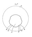
- FIG. 1 shows a plan view in the axial direction of a shaft 12 according to the invention, to which a disc 14 according to the invention is already attached.
- a disc 14 is an application for an eccentric screw or eccentric rod.
- the disc 14 is therefore eccentric and the profile is designed so that an attachment of the disc 14 to the shaft 12 is possible only in a single angular position.
- the profile on the shaft 12 consists of circular sector-shaped depressions 16, wherein the maximum depth (distance of the surface of the deepest point of the recess from the outer peripheral circle of the shaft 12) is about 1 mm and the radius of the circular sectors, which describe the depressions 16, is smaller as the radius of the shaft 12.
- four such recesses 16 are provided.
- considerably more depressions distributed over the circumference of the shank 12 can be provided.
- the upper recess has been left out to force in this way a clear angular allocation of the eccentric disc.
- a further depression can be provided at this point or all depressions can be distributed uniformly over the circumference of the shaft 12. Then, however, no clear angle assignment between shaft 12 and disc 14 is ensured.
- the number of depressions can also be reduced to a single one compared to the illustrated example.
- the corresponding counter-profile on the disc 14 consists of corresponding circular sector-shaped protuberances 18th
- FIG. 2a shows the for the in FIG. 1 Profile shown required geometric constructions to further, better illustration of the profile in FIG. 1
- the recesses 16 in the shaft 12 are formed by circular sectors of circles 22 which are slightly smaller in diameter than the shaft 12.
- the recess 20 in the convex protuberance 18 of the disc 14 is bounded by a circle 24 corresponding to the enveloping circle the external thread 26 corresponds to the shaft 12 or has a slightly larger diameter than this enveloping circle and is concentric with this enveloping circle.
- FIG. 2b shows the detail X of the FIG. 2a so that the geometric construction of the recess 20 in the protuberance 18 by means of the circles 22 and 24 is clearly visible.
- FIG. 3a shows the end of a shaft 12 according to the invention, which carries an external thread 26 at its free end. This external thread is used for screwing a nut, after a corresponding disc or a corresponding gear or pinion has been pushed onto the shaft 12.
- the course of the circular sector-shaped profiles 16 is clearly visible from the side, parallel to the axis of rotation 28 of the shaft 12.
- the end of the shaft 12 is provided with a force attack 32. At these closes the external thread 26 at. After the external thread 26 then follows a profiled area 34, which includes the circular sector-shaped profile 16.
- FIG. 3b shows the in FIG. 3 shown portion of the shaft 12 seen from the force application 32 from. From inside to outside you can see the force attack 32, the external thread 26 and behind the profiled shaft portion 34 with the depressions 16.
- the enveloping circle 26 is drawn here so that the entire underlying course of the depressions 16 is shown in solid. It should be noted that in nature the inner regions of the recesses 16 are obscured by the outer enveloping circle of the external thread 26 and therefore should not be represented according to the rules of technical drawing.
- FIG. 3b but better suited to understand the function of the present invention, and in particular the shape of the cut-out in the disc 14.
- the profilings 16 on the shank 12 are actually deeper than the outer enveloping circle of the external thread 26.
- FIG. 4 is the cut BB the FIG. 3b , therefore, only one of the recesses 16 of the profile is shown, wherein the transition 30 of this profile 16 in the normal circumferential surface of the shaft 12 can be seen. In the present case, this transition occurs at an angle of 45 °, but it is also possible to choose smaller or steeper angles for this transition. In this way, the self-centering and self-alignment of a patch on this shaft hub part when tightening a nut screwed onto the external thread 26 is ensured.
- the design of the shaft 12 according to the invention also has the advantage that the shaft 12 can be produced entirely by compression molding and rolling or rolling without any subsequent rework such as grinding or milling being necessary.
- the profile according to the invention even has a better torque transmission than a prior art hexagon profile of the same size.
Landscapes
- Engineering & Computer Science (AREA)
- General Engineering & Computer Science (AREA)
- Mechanical Engineering (AREA)
- Gears, Cams (AREA)
- Rolling Contact Bearings (AREA)
- Pulleys (AREA)
- Transmission Devices (AREA)
Claims (12)
- Tige, tourillon ou arbre pourvu(e) d'un profil (16, 18, 20) pour la transmission de couples de rotation entre un moyeu ou une autre pièce (14) et la tige, le tourillon ou l'arbre (12), qui sont pourvus du profil (16, 18, 20) et d'un filet externe ininterrompu (26) se raccordant à celui-ci, dans lequel ou laquelle le moyeu (14) est fixé par un écrou vissé sur le filet externe (26), caractérisé(e) en ce que la différence entre le diamètre externe du filet externe (26) et le cercle enveloppant externe du profil (16, 18, 20) atteint au maximum 1 mm et le point le plus bas du profil (16) sur la tige, le tourillon ou l'arbre (12) se situe radialement plus profondément que le diamètre du filet externe (26) après laminage ou roulage des filets et le moyeu (14) ou d'autres pièces à profil négatif de la tige, du tourillon ou de l'arbre peut ou peuvent malgré tout être appliqués sur le filet externe (26).
- Tige, tourillon ou arbre pourvu(e) d'un profil (16, 18, 20) selon la revendication 1, caractérisé(e) en ce que le profil côté tige, tourillon ou arbre est formé de cavités (16) en forme de secteurs de cercle dans la tige, le tourillon ou l'arbre, et le profil côté moyeu est formé de protubérances correspondantes (18) en forme de secteurs de cercle, qui présentent, au centre, des évidements en forme de secteurs de cercle, de sorte que, lors de l'engagement des profils (16, 18, 20), une section transversale reste ouverte, qui corresponde à la section transversale d'une lentille convexe et que le point le plus bas du profil (16) de la tige, du tourillon ou de l'arbre (12) soit tout aussi profond que le diamètre du filet externe (26) l'était à l'état brut, donc avant laminage ou roulage des filets.
- Tige, tourillon ou arbre pourvu(e) d'un profil (16, 18, 20) selon la revendication 2, dans lequel ou laquelle il y a sur le tourillon ou l'arbre (12) à côté du profil (16, 18, 20) un filet externe (26) qui sert à bloquer le moyeu correspondant (14) par vissage d'un écrou, caractérisé(e) en ce que les évidements (20) en forme de secteurs de cercle sont ménagés dans le profil côté moyeu (18) à l'état monté du moyeu concentriquement au filet externe (26) et présentent un rayon de la forme de secteur de cercle qui est à peine plus grand que le rayon externe du filet externe (26).
- Tige, tourillon ou arbre pourvu(e) d'un profil (16, 18, 20) selon la revendication 2 ou la revendication 3, caractérisé(e) en ce que la profondeur des profils (16) appliqués sur le tourillon ou l'arbre (12) se réduit dans le sens d'enfichage du moyeu (14).
- Tige, tourillon ou arbre pourvu(e) d'un profil (16, 18, 20) selon les revendications 1, 2, 3 ou 4, caractérisé(e) en ce que le profil (16) sur l'arbre (12), la tige ou le tourillon est fabriqué sans enlèvement de copeaux exclusivement par emboutissage, laminage et/ou roulage.
- Tige, tourillon ou arbre pourvu(e) d'un profil (16, 18, 20) selon les revendications 1, 2, 3, 4 ou 5, caractérisé(e) en ce qu'au moins 3, de préférence 5 cavités (16) sont ménagées sur l'arbre (12) ou le tourillon.
- Liaison par couple de rotation entre un moyeu ou un disque (14) et un arbre, un tourillon ou une tige (12), dans laquelle le moyeu ou le disque (14) est pourvu d'un ouverture de passage profilée pour l'arbre, le tourillon ou la tige (12) et ceux-ci sont pourvus d'un profilage externe correspondant (16) et d'un filet externe ininterrompu (26) se raccordant à ce profilage externe (16), lequel filet externe sert au vissage d'un écrou pour bloquer le moyeu ou le disque (14), caractérisée en ce que la différence entre le diamètre externe du filet externe (26) et le cercle enveloppant externe du profil (16, 18, 20) atteint au maximum 1 mm et le point le plus bas du profilage externe (16) se situe radialement plus profondément que le diamètre du filet externe (26) après laminage ou roulage des filets et le moyeu (14) ou le disque peut malgré tout être appliqué sur le filet externe (26).
- Liaison par couple de rotation selon la revendication 7, caractérisée en ce que le profilage externe (16) de l'arbre, du tourillon ou de la tige est formé de cavités (16) en forme de secteurs de cercle s'étendant parallèlement à l'axe de rotation dans l'arbre, le tourillon ou la tige (12), et le profil de l'ouverture de passage est conçu avec des protubérances correspondantes (18) en forme de secteurs de cercle, qui présentent, au centre, des évidements en forme de secteurs de cercle, de sorte que, lors de l'engagement des profilages (16, 18, 20), une section transversale (20) reste ouverte, qui corresponde à la section transversale d'une lentille convexe et que le point le plus bas du profilage externe (16) soit tout aussi profond que le diamètre du filet externe (26) l'était à l'état brut, donc avant le laminage ou le roulage des filets.
- Liaison par couple de rotation selon la revendication 8, dans laquelle il y a sur l'arbre, le tourillon ou la tige (12) à côté du profilage (16, 18, 20) encore un filet externe (26) qui sert à bloquer le moyeu ou le disque correspondant (14) par vissage d'un écrou sur ce filet externe (26), caractérisée en ce que les évidements (20) en forme de secteurs de cercle sont ménagés dans le profil côté moyeu ou disque (14) à l'état monté du moyeu ou du disque concentriquement au filet externe (26) et présentent un rayon des secteurs de cercle qui est à peine plus grand que le rayon externe du filet externe (26).
- Liaison par couple de rotation selon la revendication 8 ou la revendication 9, caractérisée en ce que la profondeur des profils (16) appliqués sur l'arbre, le tourillon ou la tige (12) se réduit dans le sens d'enfichage du moyeu ou du disque (14).
- Liaison par couple de rotation selon les revendications 8, 9 ou 10, caractérisée en ce que le profil (16) sur l'arbre, le tourillon ou la tige (12) est fabriqué sans enlèvement de copeaux exclusivement par emboutissage, laminage et/ou roulage.
- Liaison par couple de rotation selon les revendications 8, 9, 10 ou 11, caractérisée en ce qu'au moins 3, de préférence 5 cavités (16) sont ménagées sur l'arbre, le tourillon ou la tige (12).
Applications Claiming Priority (2)
| Application Number | Priority Date | Filing Date | Title |
|---|---|---|---|
| DE202009000623U DE202009000623U1 (de) | 2009-01-15 | 2009-01-15 | Profile zur Übertragung von Drehmomenten und drehmomentschlüssige Verbindung |
| PCT/DE2009/050080 WO2010081459A1 (fr) | 2009-01-15 | 2009-12-30 | Profil de transmission de couples de rotation et liaison par couple de rotation |
Publications (2)
| Publication Number | Publication Date |
|---|---|
| EP2379906A1 EP2379906A1 (fr) | 2011-10-26 |
| EP2379906B1 true EP2379906B1 (fr) | 2015-02-18 |
Family
ID=40459557
Family Applications (1)
| Application Number | Title | Priority Date | Filing Date |
|---|---|---|---|
| EP09813827.4A Active EP2379906B1 (fr) | 2009-01-15 | 2009-12-30 | Profil de transmission de couples de rotation et liaison par couple de rotation |
Country Status (11)
| Country | Link |
|---|---|
| US (1) | US20110274485A1 (fr) |
| EP (1) | EP2379906B1 (fr) |
| JP (1) | JP2012515310A (fr) |
| KR (1) | KR20110110186A (fr) |
| CN (1) | CN102713324A (fr) |
| AU (1) | AU2009337866A1 (fr) |
| BR (1) | BRPI0924217A2 (fr) |
| CA (1) | CA2749276A1 (fr) |
| DE (1) | DE202009000623U1 (fr) |
| MX (1) | MX2011007537A (fr) |
| WO (1) | WO2010081459A1 (fr) |
Families Citing this family (2)
| Publication number | Priority date | Publication date | Assignee | Title |
|---|---|---|---|---|
| DE202009004589U1 (de) | 2009-04-02 | 2009-06-04 | Acument Gmbh & Co. Ohg | Exzentereinstellelement und Exzenter-Scheibe dafür |
| CN106286709A (zh) * | 2016-10-07 | 2017-01-04 | 青岛征和工业股份有限公司 | 一种销轴及大功率柴油发动机链条 |
Family Cites Families (21)
| Publication number | Priority date | Publication date | Assignee | Title |
|---|---|---|---|---|
| US2135637A (en) * | 1935-04-26 | 1938-11-08 | Standard Pressed Steel Co | Setscrew |
| US2448278A (en) * | 1944-09-21 | 1948-08-31 | Minneapolis Moline Power Co | Power transmission coupling |
| US2804322A (en) * | 1954-11-23 | 1957-08-27 | Herzog Carl | Rotary element and shaft assembly |
| US2910842A (en) * | 1957-12-11 | 1959-11-03 | Sperry Rand Corp | Coupling |
| US3858942A (en) * | 1973-01-05 | 1975-01-07 | Wald Manufacturing Company Inc | Hub and axle assembly |
| US3880444A (en) * | 1974-02-22 | 1975-04-29 | Alvin C Bridges | Means to adjust wheel support pivot shaft |
| US4006993A (en) * | 1975-11-25 | 1977-02-08 | Borg-Warner Corporation | Shaft mounting arrangement |
| DE69104016T3 (de) * | 1990-11-19 | 1999-09-02 | Nippon Piston Ring Co. | Maschinenelement mit mindestens einem mit Druck auf einer Welle befestigten Verbindungsteil. |
| US5407295A (en) * | 1991-03-22 | 1995-04-18 | Kuhl; Hans | Shaft-hub linkage |
| FR2720845B1 (fr) * | 1994-06-02 | 1996-08-23 | Btr Ind | Vis de réglage. |
| US5740895A (en) * | 1996-05-22 | 1998-04-21 | Warn Industries | Integrated wheel end system |
| AU7178998A (en) * | 1996-11-14 | 1998-06-03 | Kelsey-Hayes Company | Vehicle wheel hub mounting system |
| DE19929914B4 (de) * | 1999-06-29 | 2010-09-30 | Robert Bosch Gmbh | Wischarm |
| DE20012108U1 (de) * | 2000-07-13 | 2001-11-29 | Altenloh, Brinck & Co. GmbH & Co. KG, 58256 Ennepetal | Exzenterelement |
| US7155824B2 (en) * | 2001-08-15 | 2007-01-02 | American Axle & Manufacturing, Inc. | Method of manufacturing an automotive differential having an input pinion |
| DE20209505U1 (de) | 2002-06-19 | 2002-09-05 | Altenloh, Brinck & Co. GmbH & Co. KG, 58256 Ennepetal | Bolzen-Scheiben-Anordnung und deren Elemente |
| US7125026B2 (en) * | 2002-11-01 | 2006-10-24 | Newfrey Llc | Cam-bolt assembly |
| WO2005052386A2 (fr) * | 2003-11-19 | 2005-06-09 | Alpha Stamping Company | Ensemble de fixation |
| JP4545072B2 (ja) * | 2005-09-09 | 2010-09-15 | 本田技研工業株式会社 | ポンプのロータ装置 |
| JP2008286308A (ja) * | 2007-05-17 | 2008-11-27 | Ntn Corp | 等速自在継手 |
| DE202007013473U1 (de) | 2007-09-25 | 2007-12-13 | Acument Gmbh & Co. Ohg | Exzenter-Einstellelement |
-
2009
- 2009-01-15 DE DE202009000623U patent/DE202009000623U1/de not_active Expired - Lifetime
- 2009-12-30 US US13/144,060 patent/US20110274485A1/en not_active Abandoned
- 2009-12-30 JP JP2011545626A patent/JP2012515310A/ja active Pending
- 2009-12-30 WO PCT/DE2009/050080 patent/WO2010081459A1/fr not_active Ceased
- 2009-12-30 KR KR1020117016444A patent/KR20110110186A/ko not_active Ceased
- 2009-12-30 CN CN200980154754XA patent/CN102713324A/zh active Pending
- 2009-12-30 BR BRPI0924217A patent/BRPI0924217A2/pt not_active IP Right Cessation
- 2009-12-30 MX MX2011007537A patent/MX2011007537A/es not_active Application Discontinuation
- 2009-12-30 AU AU2009337866A patent/AU2009337866A1/en not_active Abandoned
- 2009-12-30 CA CA2749276A patent/CA2749276A1/fr not_active Abandoned
- 2009-12-30 EP EP09813827.4A patent/EP2379906B1/fr active Active
Also Published As
| Publication number | Publication date |
|---|---|
| MX2011007537A (es) | 2011-08-15 |
| KR20110110186A (ko) | 2011-10-06 |
| DE202009000623U1 (de) | 2009-03-19 |
| EP2379906A1 (fr) | 2011-10-26 |
| JP2012515310A (ja) | 2012-07-05 |
| US20110274485A1 (en) | 2011-11-10 |
| CN102713324A (zh) | 2012-10-03 |
| BRPI0924217A2 (pt) | 2016-01-26 |
| CA2749276A1 (fr) | 2010-07-22 |
| WO2010081459A1 (fr) | 2010-07-22 |
| AU2009337866A1 (en) | 2011-08-04 |
Similar Documents
| Publication | Publication Date | Title |
|---|---|---|
| EP2215369B1 (fr) | Élément de réglage à excentrique | |
| EP3004666B1 (fr) | Vis | |
| DE102006005998B4 (de) | Schraubenmutter mit mindestens zwei Teilen | |
| EP2638298B1 (fr) | Écrou auto-fileteur, élément tubulaire pour la fabrication de l'écrou et assemblage vissé composé d'un écrou et d'un boulon | |
| DE10048913B4 (de) | Lösbares Verbindungselement für ein Bauteil, mit einem Schraubteil und einem Sicherungsring | |
| EP2649329B1 (fr) | Vis comprenant une tête, une tige et une collerette ondulée conique | |
| EP3405686B1 (fr) | Elément fileté en plastique et dispositif de raccordement constitué d'une pièce de support en plastique et d'un élément fileté en plastique | |
| WO2012097810A2 (fr) | Dispositif d'application de force | |
| DE102010028344A1 (de) | Gewindefurchende Schraube | |
| EP2414686A1 (fr) | Elément de réglage d'excentrique et disque d'excentrique associé | |
| EP2435721A1 (fr) | Liaison arbre-moyeu à profil polygonal | |
| EP3721102B1 (fr) | Écrou en deux parties présentant une force de pression élevée | |
| EP1308638B1 (fr) | Ecrou de blocage | |
| EP2379906B1 (fr) | Profil de transmission de couples de rotation et liaison par couple de rotation | |
| EP1291535B1 (fr) | Ecrou de blocage et procédé de fabrication | |
| EP3113960B1 (fr) | Élément de fixation | |
| DE102013208163A1 (de) | Adapter für eine Ausgangswelle eines Getriebes | |
| EP2646697A2 (fr) | Écrou autobloquant | |
| WO2015172968A1 (fr) | Dispositif pour empêcher le détachement intempestif d'un élément de serrage | |
| EP2059694B1 (fr) | Systeme de transmission avec maintien axial | |
| DE102014014086A1 (de) | Schraube und Schraubenanordnung | |
| DE102012109125A1 (de) | Lenkvorrichtung mit Winkelbegrenzung für Torsionsstab | |
| DE10212671A1 (de) | Kegelradausgleichsgetriebe | |
| DE102007017700A1 (de) | Verliersicherung für eine Nutmutter bei einer Welle-Nabe-Verbindung | |
| EP1683980B1 (fr) | Elément entraineur à bride pour joint de cardan et arbre articulé |
Legal Events
| Date | Code | Title | Description |
|---|---|---|---|
| PUAI | Public reference made under article 153(3) epc to a published international application that has entered the european phase |
Free format text: ORIGINAL CODE: 0009012 |
|
| 17P | Request for examination filed |
Effective date: 20110720 |
|
| AK | Designated contracting states |
Kind code of ref document: A1 Designated state(s): AT BE BG CH CY CZ DE DK EE ES FI FR GB GR HR HU IE IS IT LI LT LU LV MC MK MT NL NO PL PT RO SE SI SK SM TR |
|
| DAX | Request for extension of the european patent (deleted) | ||
| 17Q | First examination report despatched |
Effective date: 20121113 |
|
| GRAP | Despatch of communication of intention to grant a patent |
Free format text: ORIGINAL CODE: EPIDOSNIGR1 |
|
| INTG | Intention to grant announced |
Effective date: 20140115 |
|
| GRAP | Despatch of communication of intention to grant a patent |
Free format text: ORIGINAL CODE: EPIDOSNIGR1 |
|
| INTG | Intention to grant announced |
Effective date: 20140626 |
|
| GRAS | Grant fee paid |
Free format text: ORIGINAL CODE: EPIDOSNIGR3 |
|
| RAP1 | Party data changed (applicant data changed or rights of an application transferred) |
Owner name: ALTENLOH, BRINCK & CO. GMBH & CO. KG |
|
| GRAA | (expected) grant |
Free format text: ORIGINAL CODE: 0009210 |
|
| AK | Designated contracting states |
Kind code of ref document: B1 Designated state(s): AT BE BG CH CY CZ DE DK EE ES FI FR GB GR HR HU IE IS IT LI LT LU LV MC MK MT NL NO PL PT RO SE SI SK SM TR |
|
| REG | Reference to a national code |
Ref country code: GB Ref legal event code: FG4D Free format text: NOT ENGLISH |
|
| REG | Reference to a national code |
Ref country code: CH Ref legal event code: EP |
|
| REG | Reference to a national code |
Ref country code: AT Ref legal event code: REF Ref document number: 710791 Country of ref document: AT Kind code of ref document: T Effective date: 20150315 |
|
| REG | Reference to a national code |
Ref country code: IE Ref legal event code: FG4D Free format text: LANGUAGE OF EP DOCUMENT: GERMAN |
|
| REG | Reference to a national code |
Ref country code: DE Ref legal event code: R096 Ref document number: 502009010630 Country of ref document: DE Effective date: 20150402 |
|
| REG | Reference to a national code |
Ref country code: NL Ref legal event code: VDEP Effective date: 20150218 |
|
| REG | Reference to a national code |
Ref country code: LT Ref legal event code: MG4D |
|
| PG25 | Lapsed in a contracting state [announced via postgrant information from national office to epo] |
Ref country code: HR Free format text: LAPSE BECAUSE OF FAILURE TO SUBMIT A TRANSLATION OF THE DESCRIPTION OR TO PAY THE FEE WITHIN THE PRESCRIBED TIME-LIMIT Effective date: 20150218 Ref country code: FI Free format text: LAPSE BECAUSE OF FAILURE TO SUBMIT A TRANSLATION OF THE DESCRIPTION OR TO PAY THE FEE WITHIN THE PRESCRIBED TIME-LIMIT Effective date: 20150218 Ref country code: NO Free format text: LAPSE BECAUSE OF FAILURE TO SUBMIT A TRANSLATION OF THE DESCRIPTION OR TO PAY THE FEE WITHIN THE PRESCRIBED TIME-LIMIT Effective date: 20150518 Ref country code: SE Free format text: LAPSE BECAUSE OF FAILURE TO SUBMIT A TRANSLATION OF THE DESCRIPTION OR TO PAY THE FEE WITHIN THE PRESCRIBED TIME-LIMIT Effective date: 20150218 Ref country code: LT Free format text: LAPSE BECAUSE OF FAILURE TO SUBMIT A TRANSLATION OF THE DESCRIPTION OR TO PAY THE FEE WITHIN THE PRESCRIBED TIME-LIMIT Effective date: 20150218 Ref country code: ES Free format text: LAPSE BECAUSE OF FAILURE TO SUBMIT A TRANSLATION OF THE DESCRIPTION OR TO PAY THE FEE WITHIN THE PRESCRIBED TIME-LIMIT Effective date: 20150218 |
|
| PG25 | Lapsed in a contracting state [announced via postgrant information from national office to epo] |
Ref country code: NL Free format text: LAPSE BECAUSE OF FAILURE TO SUBMIT A TRANSLATION OF THE DESCRIPTION OR TO PAY THE FEE WITHIN THE PRESCRIBED TIME-LIMIT Effective date: 20150218 Ref country code: IS Free format text: LAPSE BECAUSE OF FAILURE TO SUBMIT A TRANSLATION OF THE DESCRIPTION OR TO PAY THE FEE WITHIN THE PRESCRIBED TIME-LIMIT Effective date: 20150618 Ref country code: LV Free format text: LAPSE BECAUSE OF FAILURE TO SUBMIT A TRANSLATION OF THE DESCRIPTION OR TO PAY THE FEE WITHIN THE PRESCRIBED TIME-LIMIT Effective date: 20150218 Ref country code: GR Free format text: LAPSE BECAUSE OF FAILURE TO SUBMIT A TRANSLATION OF THE DESCRIPTION OR TO PAY THE FEE WITHIN THE PRESCRIBED TIME-LIMIT Effective date: 20150519 |
|
| PG25 | Lapsed in a contracting state [announced via postgrant information from national office to epo] |
Ref country code: CZ Free format text: LAPSE BECAUSE OF FAILURE TO SUBMIT A TRANSLATION OF THE DESCRIPTION OR TO PAY THE FEE WITHIN THE PRESCRIBED TIME-LIMIT Effective date: 20150218 Ref country code: EE Free format text: LAPSE BECAUSE OF FAILURE TO SUBMIT A TRANSLATION OF THE DESCRIPTION OR TO PAY THE FEE WITHIN THE PRESCRIBED TIME-LIMIT Effective date: 20150218 Ref country code: RO Free format text: LAPSE BECAUSE OF FAILURE TO SUBMIT A TRANSLATION OF THE DESCRIPTION OR TO PAY THE FEE WITHIN THE PRESCRIBED TIME-LIMIT Effective date: 20150218 Ref country code: SK Free format text: LAPSE BECAUSE OF FAILURE TO SUBMIT A TRANSLATION OF THE DESCRIPTION OR TO PAY THE FEE WITHIN THE PRESCRIBED TIME-LIMIT Effective date: 20150218 Ref country code: DK Free format text: LAPSE BECAUSE OF FAILURE TO SUBMIT A TRANSLATION OF THE DESCRIPTION OR TO PAY THE FEE WITHIN THE PRESCRIBED TIME-LIMIT Effective date: 20150218 |
|
| REG | Reference to a national code |
Ref country code: DE Ref legal event code: R097 Ref document number: 502009010630 Country of ref document: DE |
|
| PG25 | Lapsed in a contracting state [announced via postgrant information from national office to epo] |
Ref country code: PL Free format text: LAPSE BECAUSE OF FAILURE TO SUBMIT A TRANSLATION OF THE DESCRIPTION OR TO PAY THE FEE WITHIN THE PRESCRIBED TIME-LIMIT Effective date: 20150218 |
|
| REG | Reference to a national code |
Ref country code: FR Ref legal event code: PLFP Year of fee payment: 7 |
|
| PLBE | No opposition filed within time limit |
Free format text: ORIGINAL CODE: 0009261 |
|
| STAA | Information on the status of an ep patent application or granted ep patent |
Free format text: STATUS: NO OPPOSITION FILED WITHIN TIME LIMIT |
|
| 26N | No opposition filed |
Effective date: 20151119 |
|
| PG25 | Lapsed in a contracting state [announced via postgrant information from national office to epo] |
Ref country code: SI Free format text: LAPSE BECAUSE OF FAILURE TO SUBMIT A TRANSLATION OF THE DESCRIPTION OR TO PAY THE FEE WITHIN THE PRESCRIBED TIME-LIMIT Effective date: 20150218 |
|
| REG | Reference to a national code |
Ref country code: DE Ref legal event code: R082 Ref document number: 502009010630 Country of ref document: DE Representative=s name: WEICKMANN & WEICKMANN PATENTANWAELTE - RECHTSA, DE Ref country code: DE Ref legal event code: R082 Ref document number: 502009010630 Country of ref document: DE Representative=s name: WEICKMANN & WEICKMANN PATENT- UND RECHTSANWAEL, DE Ref country code: DE Ref legal event code: R082 Ref document number: 502009010630 Country of ref document: DE Representative=s name: PATENTANWAELTE BECKER & MUELLER, DE |
|
| PG25 | Lapsed in a contracting state [announced via postgrant information from national office to epo] |
Ref country code: BE Free format text: LAPSE BECAUSE OF NON-PAYMENT OF DUE FEES Effective date: 20151231 |
|
| PG25 | Lapsed in a contracting state [announced via postgrant information from national office to epo] |
Ref country code: LU Free format text: LAPSE BECAUSE OF FAILURE TO SUBMIT A TRANSLATION OF THE DESCRIPTION OR TO PAY THE FEE WITHIN THE PRESCRIBED TIME-LIMIT Effective date: 20151230 Ref country code: MC Free format text: LAPSE BECAUSE OF FAILURE TO SUBMIT A TRANSLATION OF THE DESCRIPTION OR TO PAY THE FEE WITHIN THE PRESCRIBED TIME-LIMIT Effective date: 20150218 |
|
| REG | Reference to a national code |
Ref country code: CH Ref legal event code: PL |
|
| GBPC | Gb: european patent ceased through non-payment of renewal fee |
Effective date: 20151230 |
|
| REG | Reference to a national code |
Ref country code: IE Ref legal event code: MM4A |
|
| PG25 | Lapsed in a contracting state [announced via postgrant information from national office to epo] |
Ref country code: IE Free format text: LAPSE BECAUSE OF NON-PAYMENT OF DUE FEES Effective date: 20151230 Ref country code: GB Free format text: LAPSE BECAUSE OF NON-PAYMENT OF DUE FEES Effective date: 20151230 Ref country code: CH Free format text: LAPSE BECAUSE OF NON-PAYMENT OF DUE FEES Effective date: 20151231 Ref country code: LI Free format text: LAPSE BECAUSE OF NON-PAYMENT OF DUE FEES Effective date: 20151231 |
|
| REG | Reference to a national code |
Ref country code: FR Ref legal event code: PLFP Year of fee payment: 8 |
|
| REG | Reference to a national code |
Ref country code: AT Ref legal event code: MM01 Ref document number: 710791 Country of ref document: AT Kind code of ref document: T Effective date: 20151230 |
|
| PG25 | Lapsed in a contracting state [announced via postgrant information from national office to epo] |
Ref country code: HU Free format text: LAPSE BECAUSE OF FAILURE TO SUBMIT A TRANSLATION OF THE DESCRIPTION OR TO PAY THE FEE WITHIN THE PRESCRIBED TIME-LIMIT; INVALID AB INITIO Effective date: 20091230 Ref country code: AT Free format text: LAPSE BECAUSE OF NON-PAYMENT OF DUE FEES Effective date: 20151230 Ref country code: SM Free format text: LAPSE BECAUSE OF FAILURE TO SUBMIT A TRANSLATION OF THE DESCRIPTION OR TO PAY THE FEE WITHIN THE PRESCRIBED TIME-LIMIT Effective date: 20150218 Ref country code: BG Free format text: LAPSE BECAUSE OF FAILURE TO SUBMIT A TRANSLATION OF THE DESCRIPTION OR TO PAY THE FEE WITHIN THE PRESCRIBED TIME-LIMIT Effective date: 20150218 |
|
| PG25 | Lapsed in a contracting state [announced via postgrant information from national office to epo] |
Ref country code: CY Free format text: LAPSE BECAUSE OF FAILURE TO SUBMIT A TRANSLATION OF THE DESCRIPTION OR TO PAY THE FEE WITHIN THE PRESCRIBED TIME-LIMIT Effective date: 20150218 |
|
| PG25 | Lapsed in a contracting state [announced via postgrant information from national office to epo] |
Ref country code: MT Free format text: LAPSE BECAUSE OF FAILURE TO SUBMIT A TRANSLATION OF THE DESCRIPTION OR TO PAY THE FEE WITHIN THE PRESCRIBED TIME-LIMIT Effective date: 20150218 Ref country code: TR Free format text: LAPSE BECAUSE OF FAILURE TO SUBMIT A TRANSLATION OF THE DESCRIPTION OR TO PAY THE FEE WITHIN THE PRESCRIBED TIME-LIMIT Effective date: 20150218 |
|
| REG | Reference to a national code |
Ref country code: FR Ref legal event code: PLFP Year of fee payment: 9 |
|
| PG25 | Lapsed in a contracting state [announced via postgrant information from national office to epo] |
Ref country code: MK Free format text: LAPSE BECAUSE OF FAILURE TO SUBMIT A TRANSLATION OF THE DESCRIPTION OR TO PAY THE FEE WITHIN THE PRESCRIBED TIME-LIMIT Effective date: 20150218 Ref country code: PT Free format text: LAPSE BECAUSE OF FAILURE TO SUBMIT A TRANSLATION OF THE DESCRIPTION OR TO PAY THE FEE WITHIN THE PRESCRIBED TIME-LIMIT Effective date: 20150218 |
|
| REG | Reference to a national code |
Ref country code: DE Ref legal event code: R082 Ref document number: 502009010630 Country of ref document: DE Representative=s name: PATENTANWAELTE BECKER & MUELLER, DE |
|
| REG | Reference to a national code |
Ref country code: DE Ref legal event code: R082 Ref document number: 502009010630 Country of ref document: DE Representative=s name: PATENTANWAELTE BECKER & MUELLER, DE Ref country code: DE Ref legal event code: R081 Ref document number: 502009010630 Country of ref document: DE Owner name: ABC UMFORMTECHNIK GMBH & CO. KOMMANDITGESELLSC, DE Free format text: FORMER OWNER: ALTENLOH, BRINCK & CO. GMBH & CO. KG, 58256 ENNEPETAL, DE |
|
| PGFP | Annual fee paid to national office [announced via postgrant information from national office to epo] |
Ref country code: FR Payment date: 20251218 Year of fee payment: 17 |
|
| PGFP | Annual fee paid to national office [announced via postgrant information from national office to epo] |
Ref country code: DE Payment date: 20251222 Year of fee payment: 17 |
|
| PGFP | Annual fee paid to national office [announced via postgrant information from national office to epo] |
Ref country code: IT Payment date: 20251231 Year of fee payment: 17 |