EP2379933B1 - Isolations styréniques enroulables pour tuyau - Google Patents
Isolations styréniques enroulables pour tuyau Download PDFInfo
- Publication number
- EP2379933B1 EP2379933B1 EP09833986.4A EP09833986A EP2379933B1 EP 2379933 B1 EP2379933 B1 EP 2379933B1 EP 09833986 A EP09833986 A EP 09833986A EP 2379933 B1 EP2379933 B1 EP 2379933B1
- Authority
- EP
- European Patent Office
- Prior art keywords
- thermal insulation
- tape
- styrene
- pipe
- layer
- Prior art date
- Legal status (The legal status is an assumption and is not a legal conclusion. Google has not performed a legal analysis and makes no representation as to the accuracy of the status listed.)
- Active
Links
Images




Classifications
-
- F—MECHANICAL ENGINEERING; LIGHTING; HEATING; WEAPONS; BLASTING
- F16—ENGINEERING ELEMENTS AND UNITS; GENERAL MEASURES FOR PRODUCING AND MAINTAINING EFFECTIVE FUNCTIONING OF MACHINES OR INSTALLATIONS; THERMAL INSULATION IN GENERAL
- F16L—PIPES; JOINTS OR FITTINGS FOR PIPES; SUPPORTS FOR PIPES, CABLES OR PROTECTIVE TUBING; MEANS FOR THERMAL INSULATION IN GENERAL
- F16L11/00—Hoses, i.e. flexible pipes
- F16L11/14—Hoses, i.e. flexible pipes made of rigid material, e.g. metal or hard plastics
- F16L11/16—Hoses, i.e. flexible pipes made of rigid material, e.g. metal or hard plastics wound from profiled strips or bands
-
- F—MECHANICAL ENGINEERING; LIGHTING; HEATING; WEAPONS; BLASTING
- F16—ENGINEERING ELEMENTS AND UNITS; GENERAL MEASURES FOR PRODUCING AND MAINTAINING EFFECTIVE FUNCTIONING OF MACHINES OR INSTALLATIONS; THERMAL INSULATION IN GENERAL
- F16L—PIPES; JOINTS OR FITTINGS FOR PIPES; SUPPORTS FOR PIPES, CABLES OR PROTECTIVE TUBING; MEANS FOR THERMAL INSULATION IN GENERAL
- F16L11/00—Hoses, i.e. flexible pipes
- F16L11/04—Hoses, i.e. flexible pipes made of rubber or flexible plastics
- F16L11/08—Hoses, i.e. flexible pipes made of rubber or flexible plastics with reinforcements embedded in the wall
- F16L11/081—Hoses, i.e. flexible pipes made of rubber or flexible plastics with reinforcements embedded in the wall comprising one or more layers of a helically wound cord or wire
- F16L11/083—Hoses, i.e. flexible pipes made of rubber or flexible plastics with reinforcements embedded in the wall comprising one or more layers of a helically wound cord or wire three or more layers
-
- F—MECHANICAL ENGINEERING; LIGHTING; HEATING; WEAPONS; BLASTING
- F16—ENGINEERING ELEMENTS AND UNITS; GENERAL MEASURES FOR PRODUCING AND MAINTAINING EFFECTIVE FUNCTIONING OF MACHINES OR INSTALLATIONS; THERMAL INSULATION IN GENERAL
- F16L—PIPES; JOINTS OR FITTINGS FOR PIPES; SUPPORTS FOR PIPES, CABLES OR PROTECTIVE TUBING; MEANS FOR THERMAL INSULATION IN GENERAL
- F16L59/00—Thermal insulation in general
- F16L59/02—Shape or form of insulating materials, with or without coverings integral with the insulating materials
- F16L59/027—Bands, cords, strips or the like for helically winding around a cylindrical object
-
- F—MECHANICAL ENGINEERING; LIGHTING; HEATING; WEAPONS; BLASTING
- F16—ENGINEERING ELEMENTS AND UNITS; GENERAL MEASURES FOR PRODUCING AND MAINTAINING EFFECTIVE FUNCTIONING OF MACHINES OR INSTALLATIONS; THERMAL INSULATION IN GENERAL
- F16L—PIPES; JOINTS OR FITTINGS FOR PIPES; SUPPORTS FOR PIPES, CABLES OR PROTECTIVE TUBING; MEANS FOR THERMAL INSULATION IN GENERAL
- F16L59/00—Thermal insulation in general
- F16L59/14—Arrangements for the insulation of pipes or pipe systems
- F16L59/153—Arrangements for the insulation of pipes or pipe systems for flexible pipes
Definitions
- the present invention relates to polymeric pipe insulations based on styrenic materials for insulating and protecting flexible fluid and/or gas transport conduits.
- the insulations are in a form which can be wrapped around the conduit in one or more layers.
- thermal coatings to insulate and protect off-shore transport conduits operating at high temperatures in water greater than 1,000 metres.
- the coatings In order to maintain the conduit at the required operating temperatures at these depths and to prevent the formation of hydrates and waxes that would compromise pumping efficiency of the fluid in the conduit, the coatings must have low thermal conductivity. Thermal conductivity is decreased through foaming of the coating to some required degree, but the coating must maintain high enough thermal stability and compressive creep resistance to withstand the operating temperatures and hydrostatic pressures acting on the coating in deep water. Without sufficient compressive strength, the insulation will be compressed in thickness, thereby increasing thermal conductivity and altering the dimensions and the thermal and hydrodynamic performance of the system. Also, it is important that the coating remain sufficiently ductile after application on the conduit to prevent cracking during handling and installation, for example during reeling of the conduit onto a lay barge and subsequent deployment therefrom.
- the invention is defined by the subject-matter of claim 1.
- Optional features are subject-matter of the dependent claims.
- the invention relates to a styrenic thermal insulation product in the form of a tape or band which is adapted to be wound around a rigid or flexible pipe to form one or more thermal insulation layers in accordance with the invention, as well as insulated fluid and/or gas transport conduits incorporating such thermal insulation layers.
- fluid and/or gas transport conduits are intended to include such oil and gas pipelines and related components, including flowlines, risers, jumpers, spools, manifolds and ancillary equipment.
- tape or “band” as used herein refers to a flexible strip of material having a longitudinal dimension or length which is substantially greater than its transverse dimension or width, and which is generally flat with a thickness or height which is less than its transverse dimension.
- the pre-formed thermal insulation tape may preferably be supplied in the form of a roll which can be unwound during application to the pipe.
- the tape may be wound around the pipe in a helical pattern, with individual windings of the tape either being spaced apart or overlapping each other at their edges so as to provide a continuous layer of insulating material.
- the tape of insulating material may have a rectangular cross section and may comprise one or more layers of thermal insulation and/or other optional layers. These layers may be separately formed and then adhered together, or they may be co-extruded.
- the thermal insulation layers may be solid (unfoamed) or foamed.
- the tape may include an inner layer comprised of a foamed thermal insulation material and an outer, abrasion-resistant top coat which may be comprised of an unfoamed layer of polymer which is the same as or different from the polymer making up the foamed layer.
- the tape of thermal insulating material may have a core layer which is foamed, with the core layer being surrounded by an outer surface layer of unfoamed polymer material.
- the individual windings of thermal insulation material When applied to a rigid pipe, it may be preferred to adhere the individual windings of thermal insulation material to each other and/or to the pipe so as to form a continuous, bonded insulation layer. In this regard, it may be preferred to fuse the individual windings of insulating material to each other and to the pipe by application of heat. It may also be preferred to provide one surface of the band or tape of material with a layer of adhesive, for example by co-extrusion. The adhesive layer would be applied to the face of the insulating band or tape which comes into contact with the pipe surface, to adhere the tape or band to the pipe and also join together the overlapping edges of adjacent windings of insulating material.
- the tape of thermal insulating material may also be applied to fluid and/or gas transport conduits comprised of flexible pipes.
- the insulating tape will be applied to a flexible pipe as an unbonded insulation layer, i.e. wherein the individual windings are not adhered or bonded to either the surface of the pipe or to each other.
- Fluid and/or gas transport conduits comprised of flexible pipes may be used in petroleum production installations for the transport of fluids and gases through varying depths of water, as in risers which carry hot fluids such as hydrocarbons from depths in excess of 1,000 meters to the surface.
- Such flexible pipes may be of the "rough-bore” type, having an inner layer or “carcass” comprised of a helical winding of interlocking strips of metal.
- the flexible pipe may be of the "smooth-bore” type, having an inner polymeric liner.
- the insulating tapes according to the present invention are applicable to a wide variety of flexible pipe structures, including the rough bore and smooth bore varieties described above.
- Figure 1 illustrates a typical flexible pipe structure 50 of the "rough bore” type having an inner carcass 52 comprised of a helically wound metal strip which forms an inner, permeable layer which is flexible and has high mechanical strength.
- an inner liner 54 formed from an extruded layer of impermeable, heat resistant polymeric material which forms an impervious barrier between the exterior and interior of the pipe 50.
- Wrapped around the inner liner 54 are one or more layers of flexible pressure armour 56, 58, which are in the form of interlocking metal strips and are helically wound around the inner liner 54 at a relatively large angle to the longitudinal direction.
- the pressure armour layers 56, 58 absorb radial forces arising as a result of pressure from inside or outside the pipe 50.
- the outermost layer of pipe 50 comprises an outer sheath 64 which may preferably be comprised of an extruded layer of abrasion-resistant polymeric material.
- the thermal insulation layer 66 may comprise at least one length of thermal insulation tape 68 which is helically wound around the entire length of pipe 50 in one or more layers so as to provide the pipe 50 with a continuous layer of thermal insulation.
- the number of layers of thermal insulation tape 68 making up thermal insulation layer 66 depends on a number of factors, including geometrical (pipe size) and thermal (required loss coefficient) considerations, as well as the thickness of the insulation tape 68. Generally speaking, where the thickness of the insulation tape is from 5 - 10 mm, about 5 - 10 layers of insulation tape 68 may be applied to the pipe.
- the individual windings of the tape 68 may be spaced apart or may overlap one another, as further described below. It will be appreciated that the pipe 50 may be provided with two or more consecutively applied thermal insulation layers 66.
- the thermal insulation layer 66 also has an articulated structure so as not to impair flexibility of the pipe 50.
- This articulated structure may be provided by forming the thermal insulation tape with a cross-sectional shape which permits a limited amount of relative movement (also referred to herein as "slippage") in the longitudinal direction while maintaining overlap between adjacent windings of the tape.
- a cross-sectional shape which permits a limited amount of relative movement (also referred to herein as "slippage") in the longitudinal direction while maintaining overlap between adjacent windings of the tape.
- a wide variety of cross-sectional shapes are possible, including those specifically described below.
- the thermal insulation tape is provided with a cross-section which permits interlocking or overlapping of the windings and/or layers of tape, when the tape is applied as one or more layers.
- the tape may include a flat, planar portion which is adapted to lie flat on the surface of the pipe 50 or another layer of thermal insulation tape, and an interlocking or overlapping portion which is connected to the flat, planar portion and extends therefrom.
- the flat planar portions of the tape are preferably not adhered to one another or to the pipe 50, so as to permit slippage of the individual windings of the tape relative to the pipe, in a direction parallel to the longitudinal axis of the pipe.
- the insulation tape may be provided with one or more interlocking or overlapping portions, depending on its cross-sectional shape.
- the interlocking or overlapping portions of adjacent windings of the tape are adapted to nest with one another and to permit a limited range of longitudinal slippage of the windings, while maintaining overlap between the edges of adjacent windings.
- the thermal insulation tape 68 comprises an interlocking U-shape or C-shape, having a flat, planar portion 70 with a first major surface 72 and an opposed second major surface 74, and having transversely spaced edge portions 76 and 78.
- the first major surface 72 is provided with a pair of locking portions in the form of legs 80 and 82 which are located in edge portions 76, 78 of the tape 68 and extend continuously along its length.
- the legs 80, 82 are of the same height and extend at an angle of about 90° from the flat planar portion 70 of tape 68, although the angle may vary from about 45-90°.
- the thermal insulation layer 66 is made up of two individual lengths or layers of tape, labelled 68a and 68b.
- Length 68a forms an inner portion of insulation layer 66 and is wound around pipe 50 with its first surface 72 and legs 80, 82 facing away from the pipe 50.
- Length 68b forms an outer portion of insulation layer 66 and is wound around pipe 50 with its first surface 72 and legs 80, 82, facing toward the pipe 50.
- each leg 80, 82 of the respective lengths 68a, 68b of tape 68 nest with one another such that each leg 80 or 82 of a winding of length 68a is nested between two legs 80, 82 of an adjacent winding of length 68b, and vice versa.
- Each leg 80 or 82 of each winding of tape 68 also engages the first surface 72 of an adjacent winding of tape 68.
- the edge portions 76, 78 of the flat planar portions 70 overlap one another so that the two layers 68a, 68b of tape will maintain a continuous layer of insulation along the length of pipe 50.
- the legs 80, 82 are positioned so as to act as stops which limit the maximum amounts of longitudinal slippage of the flat planar portions 70 during bending of pipe 50.
- Figure 4 illustrates an interlocking thermal insulation tape 83 having a T-shaped cross section, including a flat planar portion 84 with a first major surface 86, a second major surface 88 and transversely spaced edge portions 90 and 92. Extending from the first surface 86 at an angle of about 90° is a locking portion in the form of leg 94, the leg 94 being positioned approximately midway between the edge portions 90, 92 so as to form the T-shape. It is not required that the leg 94 extends at an angle of 90° from the flat planar portion 84, but rather the angle may be in the range from 45-90°.
- the thermal insulation layer 66 in this example is made up of two individual lengths or layers of the T-shaped tape 83, a first length 83a which is wrapped around pipe 50 with its first surface 86 and leg 94 facing away from the pipe 50 and a second length 83b which has its first surface 86 and leg 94 facing inwardly toward the pipe 50.
- the legs 94 of lengths 83a and 83b nest with one another to limit slippage of the flat planar portions 84, with each leg 94 of each winding of length 83a nested between the legs 94 of two adjacent windings of length 83b, and vice versa.
- the leg 94 of each winding of tape 83 engages the edge portions of two adjacent windings of tape 83.
- FIG. 5 Yet another interlocking cross-sectional shape is illustrated in Figure 5 , illustrating a thermal insulation tape 95 having a Z-shaped or S-shaped cross section.
- Tape 95 includes a flat planar portion 96 having a first major surface 98 and a second major surface 100 and edge portions 102 and 104.
- Tape 95 is also provided with a pair of legs 106, 108, each of which extends at an angle of about 90° from opposite surfaces of the tape 95.
- leg 106 extends from the first major surface 98 and leg 108 extends from the second major surface 100, with leg 106 being located in edge portion 102 and leg 108 extending in the opposite direction from edge portion 104. It is not required that the legs 106, 108 extend at an angle of 90° from the flat planar portion 96, but rather the angle may be in the range from 45-90°.
- the thermal insulation layer 66 can be formed from a single length of tape 95.
- the first major surface 98 may be provided with a shoulder 110 which reduces the thickness of the flat planar portion 96 of tape 95 proximal to the leg 106 and the second major surface 100 is similarly provided with a shoulder 112 which reduces the thickness of the flat planar portion 96 of tape 95 proximal to the leg 108.
- a longitudinally-extending groove 114 is formed between shoulder 110 and leg 106 which houses the leg 108 of an adjacent winding of tape 95
- a longitudinally-extending groove 116 is formed between shoulder 112 and leg 108 which houses the leg 106 of an adjacent winding of tape 95.
- the grooves 114, 116 each have a transverse width sufficient to permit limited relative slippage of adjacent windings of tape 95 while maintaining overlap between the edge portions 102, 104 of adjacent windings of tape 95.
- the insulating tapes according to the invention may be of a single or multi-layer construction.
- these insulating tapes are preferably not provided with adhesive layers on their outer surfaces.
- the insulation tapes described herein may be provided with an inner core layer comprised of a foamed polymeric material in order to provide the desired thermal insulating properties, with an outer unfoamed layer of polymeric material surrounding the core layer and providing the desired mechanical properties.
- the foamed and unfoamed layers may be formed from the same or different polymeric materials and may preferably be formed by co-extrusion.
- Figures 3-5 illustrate examples of insulation tapes having a central core layer of foamed polymeric material and a surrounding surface layer of unfoamed polymeric material.
- the leg 94 may be relatively thick so the foamed core layer 118 extends throughout the flat planar portion 84 and the leg 94, with a surface layer 120 of unfoamed polymeric material being provided over the core layer 118.
- the legs may be relatively thin and therefore, to ensure that the legs have sufficient mechanical strength, the foamed core layer may be present only in the flat planar portion of the tape 68 or 95.
- the flat planar portion 70 of tape 68 is provided with a core layer 122 of foamed polymeric material whereas the surface layer 124 of the flat planar portion 70 and the legs 80, 82 are formed entirely from unfoamed polymeric material.
- the flat planar portion 96 of tape 95 is provided with a core layer 126 of foamed polymeric material, while the surface layer 128 of the flat planar portion 96 and the legs 106, 108 are formed entirely from unfoamed polymeric material.
- Figures 6 to 8 illustrate thermal insulation tape profiles in which the tape is provided with overlapping portions which do not interlock in the manner described above with reference to Figures 2 to 5 .
- the tapes according to Figures 6 to 8 are nevertheless constructed so as to maintain adequate overlap between the edges of adjacent windings during limited longitudinal slippage of the windings caused by bending of the pipe 50.
- the appearance of the pipe in Figures 6 to 8 is greatly oversimplified by eliminating details of construction from all layers but the insulation layer 66.
- the relative thicknesses of the various layers of pipe 50 in Figures 6 to 8 are not necessarily shown to scale.
- FIG. 6 illustrates a pipe 50 having a thermal insulation layer 66 located between the tensile armour layers 60, 62 and the outer sheath 64.
- the thermal insulation layer is comprised of a single layer 66 of a thermal insulation tape 150 having a flat planar portion 152 of approximately rectangular cross section, located between the having a first major surface 154 and a second major surface 156, with the first major surface 154 facing inwardly toward the centre of the pipe 50 and the second major surface 156 facing outwardly toward the outer sheath 64.
- the leg 158 Projecting from one edge of the flat planar portion 152 is a leg 158 which overlaps the second major surface 156 of flat planar portion 152 of an adjacent winding of tape 150, the leg 158 having sufficient width so as to maintain overlap when the separation between adjacent windings increases during bending of the pipe.
- the leg 158 and the second major surface 156 of flat planar portion 152 may have complementary shapes.
- the leg 158 is wedge-shaped and decreases in thickness with increasing distance from the flat planar portion 152, and the second major surface 156 is sloped across at least a part of its width so as to engage the wedge-shaped leg 158.
- FIG 7 illustrates a pipe 50 having a thermal insulation layer 66 located between the tensile armour layers 60, 62 and the outer sheath 64.
- the thermal insulation layer 66 is comprised of a single layer of a thermal insulation tape 160 which is similar to tape 150 of Figure 6 , having a flat planar portion 162 of approximately rectangular cross section, having a first major surface 164 and a second major surface 166, with the first major surface 164 facing inwardly toward the centre of the pipe 50 and the second major surface 166 facing outwardly toward the outer sheath 64.
- a leg 168 Projecting from one edge of the flat planar portion 162 is a leg 168 which overlaps the second major surface 166 of flat planar portion 162 of an adjacent winding of tape 160, the leg 168 having sufficient width so as to maintain overlap when the separation between adjacent windings increases during bending of the pipe.
- the leg 168 and the second major surface 166 of flat planar portion 162 have complementary shapes, with the leg 168 having a rectangular cross-section and the second major surface 166 being notched or rebated to receive the leg 168.
- FIG 8 illustrates yet another example of a pipe 50 having a thermal insulation layer 66 located between the tensile armour layers 60, 62 and the outer sheath 64.
- the thermal insulation layer 66 is comprised of an overlapping thermal insulation tape 170, which is a variant of the tape 150 shown in Figure 6 .
- Tape 170 has a flat planar portion 172 of approximately rectangular cross section, having a first major surface 174 and a second major surface 176, with the first major surface 174 facing inwardly toward the centre of the pipe 50 and the second major surface 176 facing outwardly toward the outer sheath 64.
- a leg 178 Projecting from one edge of the flat planar portion 172 is a leg 178 which overlaps the second major surface 176 of flat planar portion 172 of an adjacent winding of tape 170, the leg 178 having sufficient width so as to maintain overlap when the separation between adjacent windings increases during bending of the pipe.
- the leg 178 and the second major surface 176 of flat planar portion 172 have complementary shapes, with the leg 178 having a triangular cross-section and the second major surface 176 being chamfered along one edge to engage the triangular leg 178.
- a flexible pipe can be provided with two or more layers of any of these tapes, depending at least partly on the desired thickness of insulation layer 66 and on the thickness of the thermal insulation tape 150, 160, 170.
- adjacent layers should be applied in a staggered manner, so that the gaps between individual windings in one layer will be aligned with the flat planar portions of the tape in adjacent layer(s). For example, adjacent layers of tape may be staggered by about 50 percent.
- the insulating tapes described below and illustrated in Figures 9 and 11 are non-interlocking, nonoverlapping tapes of generally rectangular cross-section.
- the tapes of Figures 9 to 11 may be applied in two or more layers, with the gaps of adjacent layers being staggered. As mentioned above, the number of layers depends at least partly on the desired thickness of insulation layer 66 and on the thickness of the thermal insulation tapes described below.
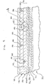
- FIG 9 illustrates a pipe 50 having a thermal insulation layer 66, according to the invention, located between the tensile armour layers 60, 62 and the outer sheath 64.
- the thermal insulation layer is comprised of an insulating tape 180 with a simple rectangular cross-section, comprising a flat planar portion with a first major surface 182, a second major surface 184 and a pair of vertical side surfaces 186, 188, the first major surface 182 facing inwardly toward the centre of the pipe 50 and the second major surface 184 facing outwardly toward sheath 64.
- the tape 180 is applied to the pipe 50 with a gap (for example about 3 mm) being provided between the side surfaces 186, 188 of adjacent windings in each layer.
- the pipe 50 may be provided with two or more layers of tape 180 so as to provide the pipe 50 with a continuous insulation layer 66, with the gaps in adjacent layers being staggered, for example by about 50 percent.
- Figures 10 and 11 illustrate variants of the rectangular insulating tape 180 of Figure 9 .
- the portions of pipe 50 shown in Figures 10 and 11 are restricted to enlarged areas A' and A", which are identical to area A of Figure 9 except for the variations in the insulation tapes described below.
- the insulation tapes of Figures 10 and 11 are intended to be applied to pipe 50 in the same manner as tape 180 of Figure 9 .
- Figure 10 illustrates insulation tape 190 having first and second major surfaces 192, 194 and side surfaces 196, 198, and being identical to the tape 180 of Figure 10 except that side surfaces 196, 198 are continuously curved between the major surfaces 192, 194.
- the tape 200 of Figure 11 is similar, having first and second major surfaces 202, 204 and side surfaces 206, 208, and being identical to the tape 190 of Figure 10 except that only the transitions between major surfaces 202, 204 and side surfaces 206, 208 are rounded, and the side surfaces 206, 208 have vertical portions located midway between the major surfaces 202, 204.
- a flexible pipe may be provided with two or more layers of tape 190 or 200 so as to provide the pipe with a continuous layer of insulation, with the gaps in adjacent layers being staggered, for example by about 50 percent.
- Figures 10 and 11 could be provided in which the transitions between the major surfaces and the side surfaces are smoothly rounded as in Figure 11 , and wherein the side surfaces are smoothly rounded as in Figure 10 .
- thermal insulation tapes illustrated in Figures 2 to 11 may be applied to a "rough bore” pipe 50 having the same construction shown in Figure 1 , or may be applied to flexible pipes having alternate structures, including the "smooth bore” pipes described above.
- thermal insulation tapes according to the present invention may exhibit all the following properties at the average operating temperature of the pipe:
- the thermal insulation layers according to the present invention are prepared from polystyrene or styrene-based thermoplastics, including polystyrene homopolymer, polystyrene copolymer, high-impact polystyrene, and modified polystyrene.
- the modified polystyrene comprises polystyrene which is blended, grafted or copolymerized with butadiene, polybutadiene, polyethylene, polypropylene, polybutene-1, polyphenylene oxide, styrene-butadiene, styrene-butadiene-styrene, styrene-isoprene-styrene, styrene-ethylene/butylene-styrene, ethylene-propylene, acrylonitrile, butadiene-acrylonitrile, ⁇ -methyl styrene, acrylic ester, methyl methacrylate, polycarbonate, or polyphenylene ether.
- Thermal insulation compositions prepared from these materials may also contain additives selected from one or more members of the group comprising inorganic fillers, reinforcing fillers, nano-fillers, conductive fillers, flame-retardant fillers, antioxidants, heat-stabilisers, process aids, compatibilisers, and colourants.
- Foamed thermal insulation layers in the insulating and protective coatings according to the invention can be prepared from the aforementioned polystyrene or styrene-based thermoplastics, by incorporating chemical foaming agents, by the physical injection of gas or volatile liquid, or by blending with hollow polymer, glass or ceramic microspheres.
- the chemical foaming agents may function through either an endothermic (heat absorbing) or exothermic (heat generating) reaction mechanism, and are selected from one or more members of the group comprising sodium bicarbonate, citric acid, tartaric acid, azodicarbonamide, 4,4-oxybis (benzene sulphonyl) hydrazide, 5-phenyl tetrazole, dinitrosopentamethylene tetramine, p-toluene sulphonyl semicarbazide, or blends thereof.
- the chemical foaming agent is an endothermic foaming agent, such as sodium bicarbonate blended with citric or tartaric acid.
- Chemical foaming occurs when the foaming agent generates a gas, usually CO 2 or N 2 , through decomposition when heated to a specific temperature.
- the initial decomposition temperature along with gas volume, release rate and solubility are important parameters when choosing a chemical foaming agent and they need to be carefully matched to the processing temperature of the particular thermoplastic being foamed.
- the gas or volatile liquid used for physical injection is selected from the group comprising CO 2 , supercritical CO 2 , N 2 , air, helium, argon, aliphatic hydrocarbons, such as butanes, pentanes, hexanes and heptanes, chlorinated hydrocarbons, such as dichloromethane and trichloroethylene, and hydrochlorofluorocarbons, such as dichlorotrifluoroethane.
- aliphatic hydrocarbons such as butanes, pentanes, hexanes and heptanes
- chlorinated hydrocarbons such as dichloromethane and trichloroethylene
- hydrochlorofluorocarbons such as dichlorotrifluoroethane.
- foaming occurs when the heated liquid vaporizes into gas.
- the physical foaming agent is supercritical CO 2 .
- the hollow microspheres are selected from one or more members of the group comprising glass, polymeric, or ceramic, including silica and alumina, microspheres.
- the hollow microspheres are lime-borosilicate glass microspheres.
- Foamed thermal insulation layers incorporating hollow microspheres are also referred to herein as "syntactic" foams.
- Extrusion may be accomplished using single screw extrusion, either in single or tandem configuration, or by twin-screw extrusion methods. When extruding foamed insulation it is important that foaming be prevented until the polymer exits the extrusion die.
- the insulation may be extruded as a single strip or as a sheet that is subsequently slit into individual strips.
- the extruder screw may be either a single stage or a 2-stage design.
- a single stage would be adequate for chemical foam extrusion whereby the foaming agent is added as a pelleted concentrate or masterbatch which is pre-mixed with the polymer to be foamed using a multi-component blender, for example, mounted over the main feed port of the extruder.
- the first and second stages are separated by a decompression zone, at which point a gas or liquid physical foaming agent can be introduced into the polymer melt via an injection or feed port in the extruder barrel.
- the first stage acts to melt and homogenize the polymer
- the second stage acts to disperse the foaming agent, cool the melt temperature, and increase the melt pressure prior to the melt exiting the die. This may also be accomplished by tandem extrusion, wherein the two stages are effectively individual single screw extruders, the first feeding into the second.
- the design of the screw is important and it may incorporate barrier flights and mixing elements to ensure effective melting, mixing, and conveying of the polymer and foaming agent.
- twin screw extrusion is preferred where the polymer to be foamed is shear sensitive or if it is required that fillers or other additives be incorporated into the foam composition. It is recommended for preparation of syntactic foams or foams prepared by physical injection of a gas or liquid foaming agent. Since the twin screw design is usually modular, comprising several separate and interchangeable screw elements, such as mixing and conveying elements, it offers great versatility in tailoring the screw profile for optimum mixing and melt processing. In the case of syntactic foams, for example, the hollow microspheres are fed directly into the polymer melt using a secondary twin-screw feeder downstream of the main feed hopper. Additionally, a static mixing attachment or gear pump may be inserted between the end of the screw and the die to further homogenize the melt, generate melt pressure, and minimize melt flow fluctuations.
- the degree of foaming is dependant upon the required balance of thermal conductivity and compressive strength. Too high a degree of foaming may be detrimental to the compressive strength and creep resistance of the foam.
- the thermoplastic foams of the present invention are typically foamed from about 5% to about 50%, more preferably 10% to 30%.
- the degree of foaming is defined herein as the degree of rarefaction, i.e. the decrease in density, and is defined as [(D matrix - D foam )/D matrix ] X 100. Expressed in this way, the degree of foaming reflects the volume percentage of gas under the assumption that the molecular weight of gas is negligible compared to that of the matrix, which is generally true. In the alternative, the degree of foaming can be measured visually by microscopic determination of cell density.
- An insulating tape with a rectangular cross-section of width 50 +/-2.5 mm and thickness 10 +/- 0.4 mm was extruded from the high impact polystyrene of Example 1 foamed to a density of 850 kg/m 3 using 0.8% of an endothermic foaming agent.
- the tape thus produced was tested for the properties in Table 1.
- wrappable styrenic pipe insulations disclosed herein may be applied between the armour layers and the outer sheath of a flexible fluid and/or gas transport conduit, it will be appreciated that the wrappable styrenic pipe insulations disclosed herein may instead or additionally be applied at other locations within the layered structure of a flexible fluid and/or gas transport conduit.
- the wrappable styrenic pipe insulations disclosed herein may be applied between the inner liner 54 and the layers of flexible pressure armour 56, 58 in the flexible pipe structure 50 described above.
Landscapes
- Engineering & Computer Science (AREA)
- General Engineering & Computer Science (AREA)
- Mechanical Engineering (AREA)
- Thermal Insulation (AREA)
Claims (10)
- Produit d'isolation thermique styrénique enroulable pour l'application à un tuyau flexible armé, comprenant :un ruban allongé comprenant une portion plane plate de section transversale généralement rectangulaire et ayant une première surface principale, une deuxième surface principale opposée, une paire de surfaces latérales opposées s'étendant entre les première et deuxième surfaces principales, une largeur et une épaisseur, dans lequel la largeur de la portion plane plate est supérieure à l'épaisseur ;dans lequel le ruban comprend du polystyrène ou une matière thermoplastique à base de styrène, caractérisé en ce que le ruban a les propriétés suivantes :une résistance à la compression uni-axiale > 25 MPa ; etune conductivité thermique ≤ 0,170 W/mK.
- Produit d'isolation thermique styrénique enroulable selon la revendication 1, dans lequel la portion plane plate est dotée de bords arrondis aux coins entre les surfaces latérales et les première et deuxième surfaces principales et dans lequel les surfaces latérales comprennent des portions droites s'étendant entre lesdits bords arrondis.
- Produit d'isolation thermique styrénique enroulable selon l'une quelconque des revendications 1 à 2, dans lequel le polystyrène ou la matière thermoplastique à base de styrène est sélectionné à partir d'un ou plusieurs éléments du groupe comprenant : un homopolymère de polystyrène, un copolymère de polystyrène, un polystyrène à résistance élevée aux chocs et un polystyrène modifié.
- Produit d'isolation thermique styrénique enroulable selon la revendication 3, dans lequel le polystyrène modifié comprend un polystyrène qui est mélangé, greffé ou copolymérisé avec du butadiène, polybutadiène, polyéthylène, polypropylène, polybutène-1, oxyde de polyphénylène, styrène-butadiène, styrène-butadiène-styrène, styrène-isoprène-styrène, styrène-éthylène/butylène-styrène, éthylène-propylène, acrylonitrile, butadiène-acrylonitrile, α-méthyle styrène, ester acrylique, méthacrylate de méthyle, polycarbonate ou éther de polyphénylène.
- Produit d'isolation thermique styrénique enroulable selon l'une quelconque des revendications 1 à 4, dans lequel le polystyrène ou la matière thermoplastique à base de styrène est non moussé.
- Produit d'isolation thermique styrénique enroulable selon l'une quelconque des revendications 1 à 4, dans lequel le polystyrène ou la matière thermoplastique à base de styrène est moussé et contient de bulles de gaz et/ou des microsphères creuses, et dans lequel un degré de moussage est d'environ 5-50 pourcent.
- Produit d'isolation thermique styrénique enroulable selon l'une quelconque des revendications 1 à 4, dans lequel le ruban allongé a une couche centrale qui est moussée et une couche superficielle entourant la couche centrale, dans lequel la couche superficiel est non moussée.
- Produit d'isolation thermique styrénique enroulable selon l'une quelconque des revendications 1 à 7, ayant une densité dans la plage d'environ 700 - 1050 kg/m3, de préférence dans la plage d'environ 850 - 1030 kg/m3.
- Tuyau flexible armé comprenant une carcasse métallique cylindrique flexible entourée par au moins une couche d'armature métallique flexible ;
dans lequel le tuyau comprend en outre une couche d'isolation thermique entourant l'armature ; dans lequel la couche d'isolation thermique est comprise entre une ou plusieurs couches de produit d'isolation thermique styrénique enroulable selon l'une quelconque des revendications 1 à 8, et dans lequel chaque couche du ruban est constituée d'une pluralité d'enroulements agencés adjacents l'un à l'autre ;
dans lequel le ruban d'isolation thermique est constitué d'une matière thermoplastique et comprend une portion plane plate qui est sensiblement parallèle à un axe défini par la carcasse et l'armature. - Tuyau flexible armé selon la revendication 9, dans lequel le tuyau comprend en outre une gaine polymérique externe disposée sur l'armature et dans lequel l'au moins une couche d'isolation thermique est située entre l'armature et la gaine polymérique externe.
Applications Claiming Priority (2)
| Application Number | Priority Date | Filing Date | Title |
|---|---|---|---|
| US13965008P | 2008-12-22 | 2008-12-22 | |
| PCT/CA2009/001891 WO2010072001A1 (fr) | 2008-12-22 | 2009-12-22 | Isolations styréniques enroulables pour tuyau |
Publications (3)
| Publication Number | Publication Date |
|---|---|
| EP2379933A1 EP2379933A1 (fr) | 2011-10-26 |
| EP2379933A4 EP2379933A4 (fr) | 2013-05-15 |
| EP2379933B1 true EP2379933B1 (fr) | 2018-05-16 |
Family
ID=42264326
Family Applications (1)
| Application Number | Title | Priority Date | Filing Date |
|---|---|---|---|
| EP09833986.4A Active EP2379933B1 (fr) | 2008-12-22 | 2009-12-22 | Isolations styréniques enroulables pour tuyau |
Country Status (5)
| Country | Link |
|---|---|
| US (1) | US8485229B2 (fr) |
| EP (1) | EP2379933B1 (fr) |
| BR (1) | BRPI0924891B1 (fr) |
| MY (1) | MY157589A (fr) |
| WO (1) | WO2010072001A1 (fr) |
Cited By (1)
| Publication number | Priority date | Publication date | Assignee | Title |
|---|---|---|---|---|
| FR3161008A1 (fr) * | 2024-04-09 | 2025-10-10 | Technipfmc Subsea France | Conduite flexible sous-marine comprenant une couche polymérique intermédiaire à base de poly(éther de p-phénylène) |
Families Citing this family (35)
| Publication number | Priority date | Publication date | Assignee | Title |
|---|---|---|---|---|
| BRPI0914973B1 (pt) | 2008-06-09 | 2022-04-26 | Flexsteel Pipeline Technologies, Inc | Equipamento para fixação de tubo flexível a tubo flexível adicional em configuração de extremidade a extremidade |
| MY163458A (en) * | 2009-03-18 | 2017-09-15 | Deepflex Inc | Composite flexible pipe and method of manufacture |
| CN103988008A (zh) | 2011-10-04 | 2014-08-13 | 弗莱克斯蒂尔管道技术股份有限公司 | 具有改进的排出性的管道端部配件 |
| US9976687B2 (en) | 2012-05-18 | 2018-05-22 | Saprex, Llc | Breathable multi-component exhaust insulation system |
| BR112015000165A2 (pt) | 2012-07-03 | 2017-06-27 | 3M Innovative Properties Co | revestimento de tubos à base de siloxano |
| CN103672221A (zh) * | 2012-09-08 | 2014-03-26 | 天津市海王星海上工程技术有限公司 | 一种适用于海洋保温混输复合软管 |
| US9388515B2 (en) | 2012-09-28 | 2016-07-12 | Saprex, Llc | Heat curable composite textile |
| US9638473B2 (en) | 2012-12-04 | 2017-05-02 | Carlsberg Breweries A/S | Beverage dispensing assembly comprising beverage distribution python and a method of producing the beverage distribution python |
| US9067397B2 (en) * | 2013-03-11 | 2015-06-30 | Changchun Gaoxiang Special Pipe Co., Ltd. | Hybrid pipe design and method of manufacture |
| BR112017006628B1 (pt) | 2014-09-30 | 2021-09-08 | Flexsteel Pipeline Technologies, Inc | Conector de tubos e método de montagem de um conector de tubos |
| CA3004049C (fr) | 2015-11-02 | 2021-06-01 | Flexsteel Pipeline Technologies, Inc. | Surveillance d'integrite en temps reel de canalisations a terre |
| JP6802901B2 (ja) | 2016-04-15 | 2020-12-23 | サプレックス,リミテッド・ライアビリティ・カンパニー | 複合材料絶縁システム |
| US10981765B2 (en) | 2016-06-28 | 2021-04-20 | Trinity Bay Equipment Holdings, LLC | Half-moon lifting device |
| US11208257B2 (en) | 2016-06-29 | 2021-12-28 | Trinity Bay Equipment Holdings, LLC | Pipe coil skid with side rails and method of use |
| EP3320032B1 (fr) * | 2016-07-15 | 2020-08-19 | SABIC Global Technologies B.V. | Matériau thermoplastique expansé, son procédé de fabrication, articles préparés à partir de celui-ci et procédé de formation d'articles |
| US11235946B2 (en) | 2016-10-10 | 2022-02-01 | Trinity Bay Equipment Holdings, LLC | Expandable drum assembly for deploying coiled pipe and method of using same |
| BR112019007181A2 (pt) | 2016-10-10 | 2019-07-02 | Trinity Bay Equipment Holdings, LLC | reboque de instalação para tubo flexível em bobina e método de utilização do mesmo |
| MX2019005812A (es) | 2016-11-18 | 2019-10-07 | Saprex Llc | Sistema de aislamiento compuesto. |
| US10526164B2 (en) | 2017-08-21 | 2020-01-07 | Trinity Bay Equipment Holdings, LLC | System and method for a flexible pipe containment sled |
| BR112020008740A2 (pt) | 2017-11-01 | 2020-10-13 | Trinity Bay Equipment Holdings, LLC | sistema e método para manuseio de carretel de tubo |
| CN111902312B (zh) | 2018-02-01 | 2023-07-18 | 圣三一海湾设备控股有限公司 | 具有侧轨的管道卷垫块及使用方法 |
| CA3092070A1 (fr) | 2018-02-22 | 2019-08-29 | Trinity Bay Equipment Holdings, LLC | Systeme et procede pour deployer des enroulements de tuyau enroulable |
| CN113165825A (zh) | 2018-10-12 | 2021-07-23 | 圣三一海湾设备控股有限公司 | 用于盘绕的柔性管材的安装拖车及其使用方法 |
| AR118122A1 (es) | 2019-02-15 | 2021-09-22 | Trinity Bay Equipment Holdings Llc | Sistema de manejo de tubo flexible y método para usar el mismo |
| US10753512B1 (en) | 2019-03-28 | 2020-08-25 | Trinity Bay Equipment Holdings, LLC | System and method for securing fittings to flexible pipe |
| US10926972B1 (en) | 2019-11-01 | 2021-02-23 | Trinity Bay Equipment Holdings, LLC | Mobile cradle frame for pipe reel |
| EP4058709B1 (fr) | 2019-11-22 | 2025-05-07 | FlexSteel USA, LLC | Systèmes et procédés de raccord de tuyau embouti |
| WO2021102318A1 (fr) | 2019-11-22 | 2021-05-27 | Trinity Bay Equipment Holdings, LLC | Systèmes et procédés de raccord de tuyau réutilisable |
| AU2020386635A1 (en) | 2019-11-22 | 2022-06-09 | Trinity Bay Equipment Holdings, LLC | Potted pipe fitting systems and methods |
| US10822194B1 (en) | 2019-12-19 | 2020-11-03 | Trinity Bay Equipment Holdings, LLC | Expandable coil deployment system for drum assembly and method of using same |
| US10844976B1 (en) | 2020-02-17 | 2020-11-24 | Trinity Bay Equipment Holdings, LLC | Methods and apparatus for pulling flexible pipe |
| GB2596283A (en) * | 2020-06-15 | 2021-12-29 | Stephen Boyce Gerard | Thermoplastic composite pipe |
| CN112963633B (zh) * | 2021-02-24 | 2021-12-07 | 中国石油大学(北京) | 一种用于海洋复合软管的抗压铠装层及其专用异型材 |
| CN115234722B (zh) * | 2022-07-13 | 2024-10-11 | 中国石油大学(北京) | 一种用于复合软管的类π型截面异型材及骨架层 |
| GB202211143D0 (en) * | 2022-07-29 | 2022-09-14 | Baker Hughes Energy Technology UK Ltd | Permeation-barrier and method of manufacture |
Family Cites Families (112)
| Publication number | Priority date | Publication date | Assignee | Title |
|---|---|---|---|---|
| US2797731A (en) * | 1955-10-06 | 1957-07-02 | Monsanto Chemicals | Method for preventing moisture condensation on cold pipes |
| DE1281676B (de) * | 1964-12-30 | 1968-10-31 | Manfred Hawerkamp | Verfahren zur Herstellung von Rohren und Behaeltern aus schraubenlinienfoermig gewickeltem Bandmaterial aus thermoplastischen Kunststoffen |
| US3731710A (en) * | 1965-08-27 | 1973-05-08 | Exxon | Spray foam insulated pipe |
| US3614967A (en) * | 1968-10-08 | 1971-10-26 | Royston Lab | Multilayered pipe coatings and coated pipe |
| CA922224A (en) * | 1969-05-17 | 1973-03-06 | Shaw Pipe Industries Ltd. | Method of applying protective coatings to pipes |
| US3654061A (en) * | 1970-11-19 | 1972-04-04 | Hood Sponge Rubber Co | Pipe wrap |
| SE362463B (fr) | 1971-08-27 | 1973-12-10 | Graenges Hedlund Ab | |
| US3755029A (en) * | 1971-11-17 | 1973-08-28 | Amchem Prod | Protective coated thermal insulation |
| DE2331643C3 (de) * | 1972-06-24 | 1975-10-09 | Mitsubishi Petrochemical Co., Ltd., Tokio | Schlauch, insbesondere Wärmeschutzschlauch |
| US3954539A (en) * | 1972-11-01 | 1976-05-04 | The Dow Chemical Company | Cryogenic construction and article therefor |
| US3929166A (en) * | 1973-08-09 | 1975-12-30 | Gen Electric | Pipeline thermal insulation |
| DE2416812C2 (de) | 1974-04-06 | 1983-04-07 | Bayer Ag, 5090 Leverkusen | Verfahren zur Herstellung von rieselfähigen Hohlperlen aus Vinylchlorid-Ethylen-Copolymerisaten |
| US4013987A (en) * | 1975-08-22 | 1977-03-22 | Westinghouse Electric Corporation | Mica tape binder |
| US4038339A (en) * | 1975-09-16 | 1977-07-26 | Westinghouse Electric Corporation | Epoxy-vinyl-polyester cold blended resin composition |
| GB1579125A (en) * | 1976-06-14 | 1980-11-12 | Sigmund F | Heat-insulated pipe-lines |
| SE439678B (sv) | 1976-10-04 | 1985-06-24 | Pont A Mousson | Vermeisolerat ror for markforleggning |
| DE2700478C2 (de) | 1977-01-07 | 1986-07-10 | Kabel- und Metallwerke Gutehoffnungshütte AG, 3000 Hannover | Verfahren zur Herstellung eines wärme- und schallisolierten Leitungsrohres |
| US4151366A (en) * | 1977-06-30 | 1979-04-24 | General Electric Company | Flame resistant, insulated multi-conductor electric cable |
| US4176106A (en) | 1977-07-28 | 1979-11-27 | Union Carbide Corporation | Phenol/formaldehyde resoles and cellular products derived therefrom |
| FR2417707A1 (fr) * | 1978-02-21 | 1979-09-14 | Coflexip | Tubes flexibles flottants |
| JPS5624289A (en) * | 1979-07-31 | 1981-03-07 | Furukawa Electric Co Ltd | Adiabatic pipe and its manufacture |
| DE8002596U1 (de) * | 1980-02-01 | 1980-05-14 | Dynamit Nobel Ag, 5210 Troisdorf | Maschine zum herstellen von dickwandigen isolierrohren aus schaumkunststoffbahnen |
| JPS5835607B2 (ja) * | 1980-03-21 | 1983-08-03 | 保土谷化学工業株式会社 | ポリウレタン変性ポリイソシアヌレ−トフオ−ムの製造法 |
| FR2479945A1 (fr) * | 1980-04-03 | 1981-10-09 | Brangues Chaudronnerie Tuyaute | Procede pour le calorifugeage des conduits, et conduits obtenus |
| SE434815B (sv) * | 1982-02-23 | 1984-08-20 | Lindab Nord Ab | Sett for framstellning av isolerade rorledningsdetaljer |
| US4523141A (en) * | 1982-04-16 | 1985-06-11 | The Kendall Company | Pipe coating |
| US4589275A (en) * | 1982-04-16 | 1986-05-20 | The Kendall Company | Pipe coating |
| US4713271A (en) * | 1982-06-30 | 1987-12-15 | Cosden Technology, Inc. | Foamed polymer tubing |
| DE3370680D1 (en) * | 1982-12-23 | 1987-05-07 | Webco Ind Rubber Ltd | Insulated pipeline |
| CA1216505A (fr) | 1983-08-26 | 1987-01-13 | James J. Stockman | Methode et dispositif pour garnir les tuyaux d'un revetement |
| CA1200216A (fr) * | 1983-12-22 | 1986-02-04 | Farrokh A. Patell | Section de pipeline a isolant thermique prefabriquee, et sa fabrication |
| DE3409734A1 (de) * | 1984-03-20 | 1985-09-26 | The Furukawa Electric Co., Ltd., Tokio/Tokyo | Biegsame rohrleitung fuer den transport fliessender medien |
| US4590108A (en) * | 1984-07-11 | 1986-05-20 | Nippe Reynold B | Method and system for insulating pipes |
| US4657050A (en) * | 1984-07-25 | 1987-04-14 | Shell Oil Company | Pipeline insulation system |
| US4603182A (en) * | 1984-10-05 | 1986-07-29 | General Electric Company | Low viscosity epoxy resin compositions |
| US4676695A (en) * | 1985-11-01 | 1987-06-30 | Union Oil Company Of California | Method for preventing thaw settlement along offshore artic pipelines |
| US4778703A (en) * | 1987-04-02 | 1988-10-18 | Compac Corporation | Adhesive tape for insulation application |
| NO163648C (no) * | 1987-04-29 | 1990-06-27 | Dag Vilnes | Fremgangsmaate til isolering av et roerlegeme som er nedsenket i vann. |
| GB2215427B (en) | 1988-03-04 | 1992-07-29 | Marathon Oil U K Ltd | Coated pipes |
| US5026451A (en) * | 1988-05-12 | 1991-06-25 | Shaw Industries Ltd. | Method and apparatus for applying thermo-plastic protective coating to pipes |
| FI82635C (sv) | 1988-08-23 | 1991-04-10 | Muotekno Ab Oy | Förfarande och anordning för sammanfogning av rörformiga plastprodukt er |
| GB8918218D0 (en) * | 1989-08-09 | 1989-09-20 | Boc Group Plc | Thermal insulation |
| GB9114585D0 (en) | 1991-07-05 | 1991-08-21 | Shell Int Research | Insulated flowline bundle |
| AU2953592A (en) | 1991-12-07 | 1993-07-19 | Thomas Christopher Arnott | Improvements relating to pipeline insulation and anticorrosion protection |
| AU659314B2 (en) | 1992-06-19 | 1995-05-11 | Shell Internationale Research Maatschappij B.V. | Polyolefin/filler composite materials and their use |
| US5597522A (en) * | 1992-06-19 | 1997-01-28 | Shell Research Limited | Method of making polyolefin/filler composite materials |
| IT1264781B1 (it) | 1993-04-06 | 1996-10-10 | Himont Inc | Procedimento per il rivestimento di tubi metallici con materiali poliolefinici |
| GB9311715D0 (en) | 1993-06-07 | 1993-07-21 | Liquid Polymers Group Plc | Improvements in or relating to pipe coating |
| DE4421817A1 (de) | 1994-06-22 | 1996-01-04 | Bayer Ag | Verfahren zur Isolierung von Rohren |
| US6155305A (en) * | 1994-08-29 | 2000-12-05 | Sumner; Glen R. | Offshore pipeline with waterproof thermal insulation |
| US5869591A (en) * | 1994-09-02 | 1999-02-09 | The Dow Chemical Company | Thermoset interpolymers and foams |
| FR2729211A1 (fr) | 1995-01-06 | 1996-07-12 | Villain Sa | Ensemble d'isolation de tuyaux forme d'elements et procede de fabrication de tels elements |
| FR2732441B1 (fr) * | 1995-03-29 | 1997-05-30 | Coflexip | Conduite tubulaire flexible a gaine d'etancheite interne polymerique |
| US6142707A (en) * | 1996-03-26 | 2000-11-07 | Shell Oil Company | Direct electric pipeline heating |
| US6264401B1 (en) * | 1995-12-29 | 2001-07-24 | Shell Oil Company | Method for enhancing the flow of heavy crudes through subsea pipelines |
| FR2743614B1 (fr) * | 1996-01-11 | 1998-02-13 | Coflexip | Canalisation flexible |
| GB9609296D0 (en) | 1996-05-03 | 1996-07-10 | Balmoral Group | Insulating coating |
| GB9613973D0 (en) * | 1996-07-03 | 1996-09-04 | Bredero Price Services | Improvements in or relating to field joints |
| CA2234313A1 (fr) * | 1997-04-07 | 1998-10-07 | Joseph A. Charlson | Elements de charpente isolants composites et systeme d'extension d'enveloppe pour edifices |
| US6058979A (en) * | 1997-07-23 | 2000-05-09 | Cuming Corporation | Subsea pipeline insulation |
| JPH1190972A (ja) * | 1997-09-18 | 1999-04-06 | Uc Sangyo Kk | 断熱ホースの製造方法 |
| US6065781A (en) * | 1998-05-29 | 2000-05-23 | Power Lone Star, Inc. | Method and apparatus for protecting the weld area of polyolefin coated pipe |
| US6199595B1 (en) * | 1998-06-04 | 2001-03-13 | Jerry G. Baker | Insulated marine pipe apparatus and method of installation |
| FR2779801B1 (fr) * | 1998-06-11 | 2000-07-21 | Inst Francais Du Petrole | Procede pour l'isolation thermique des tubings de production places dans un puits au moyen d'une mousse non rigide |
| US6382259B1 (en) * | 1998-06-22 | 2002-05-07 | Corus Uk Limited | Insulated pipework systems |
| JP3322852B2 (ja) * | 1998-06-26 | 2002-09-09 | 日清紡績株式会社 | 連続気泡硬質ポリウレタンフォーム成形体およびその製造方法 |
| US5996643A (en) * | 1998-09-18 | 1999-12-07 | Stonitsch; Lawrence J. | Foam insulation system for pipes |
| GB9905037D0 (en) * | 1999-03-05 | 1999-04-28 | Raychem Sa Nv | Method of sealing a joint between two pipes |
| GB2365096B (en) | 1999-05-26 | 2003-04-09 | Thermotite As | Steel pipe with heat insulation for deep-sea pipelines and method of producing it |
| US6145546A (en) * | 1999-06-03 | 2000-11-14 | Coflexip | Flexible flowline for conveying fluids |
| US6397895B1 (en) | 1999-07-02 | 2002-06-04 | F. Glenn Lively | Insulated pipe |
| US6527015B2 (en) * | 1999-07-02 | 2003-03-04 | F. Glenn Lively | Insulated pipe |
| GB9917733D0 (en) * | 1999-07-28 | 1999-09-29 | Kvaerner Earl & Wright | Thermal insulated pipelines |
| DE19955726C1 (de) * | 1999-11-15 | 2001-06-28 | Eupec Pipecoatings Gmbh | Vorrichtung zur Kunststoffummantelung einer Rohrleitung an Rohrverbindungen |
| GB0000243D0 (en) * | 2000-01-07 | 2000-03-01 | British Steel Ltd | Improved insulated pipework system |
| DK200000242A (da) * | 2000-02-16 | 2001-01-18 | Nkt Flexibles Is | Fleksibel armeret rørledning, samt anvendelse af samme |
| DK200000241A (da) * | 2000-02-16 | 2001-01-18 | Nkt Flexibles Is | Fleksibel armeret rørledning, samt anvendelse af samme |
| EP1174261A1 (fr) | 2000-07-20 | 2002-01-23 | Borcalis GmbH | Tuyaux de mousse de polyoléfine à une ou plusieurs couches |
| FR2817318B1 (fr) * | 2000-11-24 | 2002-12-27 | Coflexip | Conduite tubulaire flexible |
| US6505650B2 (en) * | 2001-01-03 | 2003-01-14 | Phillips Petroleum Company | Method for inhibiting corrosion under insulation on the exterior of a structure |
| WO2002063128A1 (fr) * | 2001-01-08 | 2002-08-15 | Stolt Offshore Sa | Tour de remontee marine |
| US7302973B2 (en) * | 2001-05-04 | 2007-12-04 | Nkt Flexibles I/S | Reinforced flexible pipeline having a thermal barrier |
| US6653360B2 (en) * | 2001-05-23 | 2003-11-25 | Chakra V. Gupta | Flexible foamed polyethylene |
| US6739803B2 (en) * | 2001-07-20 | 2004-05-25 | Shell Oil Company | Method of installation of electrically heated pipe-in-pipe subsea pipeline |
| US6814146B2 (en) * | 2001-07-20 | 2004-11-09 | Shell Oil Company | Annulus for electrically heated pipe-in-pipe subsea pipeline |
| CA2356451A1 (fr) | 2001-08-22 | 2003-02-22 | Chun Huang | Isolant en mousse plastique pour couvrir les tuyaux en metal, et procede de fabrication |
| DE50210899D1 (de) * | 2001-11-19 | 2007-10-25 | Ami Agrolinz Melamine Int Gmbh | Erzeugnisse, insbesondere formmassen aus triazinsegmente enthaltenden polymeren, verfahren zu deren herstellung und verwendungen |
| US6827110B2 (en) * | 2002-01-07 | 2004-12-07 | Cuming Corporation | Subsea insulated pipeline with pre-cured syntactic elements and methods of manufacture |
| GB2384535B (en) * | 2002-01-26 | 2005-06-29 | Coflexip Stena Offshore Ltd | A protective insert for a welded pipe joint |
| FR2840314B1 (fr) * | 2002-06-03 | 2004-08-20 | Inst Francais Du Petrole | Methode d'isolation thermique, procede de preparation d'un gel isolant et gel isolant obtenu |
| WO2004018919A2 (fr) * | 2002-08-21 | 2004-03-04 | The Research Foundation Of State University Of New York | Procede permettant d'ameliorer les proprietes de materiaux et materiaux ainsi ameliores |
| GB2401921B (en) | 2003-01-28 | 2006-03-01 | T J Corbishley | Improvements in submarine pipelines |
| US6887938B2 (en) * | 2003-02-04 | 2005-05-03 | General Electric Company | Compositions containing polyphenylene ether and/or polystyrene having improved tribological properties and methods for improving tribological properties of polyphenylene ether and/or polystyrene compositions |
| FR2852677B1 (fr) * | 2003-03-18 | 2006-01-06 | Saipem Sa | Dispositif de rechauffage et d'isolation thermique d'au moins une conduite sous-marine |
| US20050095380A1 (en) * | 2003-05-16 | 2005-05-05 | Lou Watkins | Insulated subsea pipe, and materials and methods for applying thermal insulation to subsea pipe |
| US7037557B2 (en) * | 2003-05-19 | 2006-05-02 | Thermacor Process, Lp | Ceramic coating process for pre-insulated piping |
| EP1649205B1 (fr) | 2003-07-27 | 2007-04-25 | Walter Stucke | Conduites en acier isolees |
| GB2407319A (en) | 2003-09-12 | 2005-04-27 | Crp Group Ltd | Thermal insulation material |
| CA2542367A1 (fr) | 2003-10-17 | 2005-04-28 | Shiina Kasei Co. | Procede pour produire une mousse plastique composite |
| US7622683B2 (en) * | 2004-07-26 | 2009-11-24 | Terry Jeffrey Corbishley | Marine and submarine pipelines |
| US6978807B1 (en) * | 2005-03-25 | 2005-12-27 | Thermacor Process, Lp | Water stop for a line installation in a pre-insulated pipeline |
| CN101227983B (zh) | 2005-06-14 | 2015-08-19 | 巴塞尔聚烯烃有限公司 | 性能改进的多层塑胶防腐蚀涂层 |
| DE102005036508B4 (de) | 2005-07-29 | 2007-07-12 | Eupec Pipecoatings Gmbh | Verfahren und Vorrichtung zur Überwachung und Detektierung von Beschichtungsdefekten einer erd- oder wasserverlegten Rohrleitung |
| NO329279B1 (no) * | 2005-11-09 | 2010-09-27 | Advanced Prod & Loading As | Fleksibel rorledning for kryogeniske fluider |
| US20080128043A1 (en) * | 2006-01-20 | 2008-06-05 | Lou Watkins | Insulated subsea pipe with flexible insulation |
| US20070292647A1 (en) * | 2006-06-16 | 2007-12-20 | Princell Charles M | Lap and seam seal closure system for foam pipe insulation |
| CA2555756A1 (fr) | 2006-08-10 | 2008-02-10 | Shawcor Ltd. | Tuyau calorifuge pour tres hautes temperatures |
| BRPI0717283A2 (pt) * | 2006-09-29 | 2013-12-10 | Offshore Joint Services Inc | Revestimento de junta de campo de linha de tubulação para juntas de campo com isolamento molhado. |
| WO2008054602A2 (fr) * | 2006-09-29 | 2008-05-08 | Offshore Joint Services, Inc. | Revêtement de joint de conduite pour isolation humide avec adhésion améliorée |
| US8714206B2 (en) | 2007-12-21 | 2014-05-06 | Shawcor Ltd. | Styrenic insulation for pipe |
| US8397765B2 (en) * | 2008-07-25 | 2013-03-19 | Shawcor Ltd. | High temperature resistant insulation for pipe |
| DK2318749T3 (da) | 2008-07-25 | 2021-01-25 | Shawcor Ltd | Højtemperaturbestandig rørisolering |
-
2009
- 2009-12-22 US US12/644,549 patent/US8485229B2/en active Active
- 2009-12-22 BR BRPI0924891A patent/BRPI0924891B1/pt active IP Right Grant
- 2009-12-22 MY MYPI2011700084A patent/MY157589A/en unknown
- 2009-12-22 EP EP09833986.4A patent/EP2379933B1/fr active Active
- 2009-12-22 WO PCT/CA2009/001891 patent/WO2010072001A1/fr not_active Ceased
Non-Patent Citations (1)
| Title |
|---|
| None * |
Cited By (1)
| Publication number | Priority date | Publication date | Assignee | Title |
|---|---|---|---|---|
| FR3161008A1 (fr) * | 2024-04-09 | 2025-10-10 | Technipfmc Subsea France | Conduite flexible sous-marine comprenant une couche polymérique intermédiaire à base de poly(éther de p-phénylène) |
Also Published As
| Publication number | Publication date |
|---|---|
| EP2379933A1 (fr) | 2011-10-26 |
| BRPI0924891B1 (pt) | 2020-01-28 |
| EP2379933A4 (fr) | 2013-05-15 |
| US20100154916A1 (en) | 2010-06-24 |
| WO2010072001A1 (fr) | 2010-07-01 |
| MY157589A (en) | 2016-06-30 |
| BRPI0924891A2 (pt) | 2015-11-24 |
| US8485229B2 (en) | 2013-07-16 |
Similar Documents
| Publication | Publication Date | Title |
|---|---|---|
| EP2379933B1 (fr) | Isolations styréniques enroulables pour tuyau | |
| US8714206B2 (en) | Styrenic insulation for pipe | |
| EP2318749B1 (fr) | Isolation résistante à la haute température pour tuyau | |
| US8397765B2 (en) | High temperature resistant insulation for pipe | |
| US10161556B2 (en) | High temperature insulated pipelines | |
| KR101333475B1 (ko) | 열 절연 파이프 | |
| CA2753024C (fr) | Tuyau pour hautes temperatures renforce par fibres | |
| US20140311614A1 (en) | High temperature resistant polysulfone insulation for pipe | |
| RU2355941C2 (ru) | Способ изготовления кожуха для гибких теплоизолированных трубопроводов | |
| KR102661361B1 (ko) | Hfo 함유 셀 가스를 가진 단열 중간 파이프 | |
| KR102152097B1 (ko) | 처짐 없는 가요성 절연재 | |
| JP2006161982A (ja) | 耐火多層管およびその製造方法 |
Legal Events
| Date | Code | Title | Description |
|---|---|---|---|
| PUAI | Public reference made under article 153(3) epc to a published international application that has entered the european phase |
Free format text: ORIGINAL CODE: 0009012 |
|
| 17P | Request for examination filed |
Effective date: 20110721 |
|
| AK | Designated contracting states |
Kind code of ref document: A1 Designated state(s): AT BE BG CH CY CZ DE DK EE ES FI FR GB GR HR HU IE IS IT LI LT LU LV MC MK MT NL NO PL PT RO SE SI SK SM TR |
|
| DAX | Request for extension of the european patent (deleted) | ||
| A4 | Supplementary search report drawn up and despatched |
Effective date: 20130411 |
|
| RIC1 | Information provided on ipc code assigned before grant |
Ipc: F16L 59/02 20060101ALI20130405BHEP Ipc: F16L 59/153 20060101AFI20130405BHEP Ipc: F16L 59/10 20060101ALI20130405BHEP Ipc: F16L 11/24 20060101ALI20130405BHEP Ipc: F16L 11/16 20060101ALI20130405BHEP Ipc: F16L 11/20 20060101ALI20130405BHEP |
|
| 17Q | First examination report despatched |
Effective date: 20160629 |
|
| REG | Reference to a national code |
Ref country code: DE Ref legal event code: R079 Ref document number: 602009052372 Country of ref document: DE Free format text: PREVIOUS MAIN CLASS: F16L0059153000 Ipc: F16L0011080000 |
|
| GRAP | Despatch of communication of intention to grant a patent |
Free format text: ORIGINAL CODE: EPIDOSNIGR1 |
|
| RIC1 | Information provided on ipc code assigned before grant |
Ipc: F16L 11/16 20060101ALI20171124BHEP Ipc: F16L 11/08 20060101AFI20171124BHEP Ipc: F16L 59/153 20060101ALI20171124BHEP Ipc: F16L 59/02 20060101ALI20171124BHEP |
|
| INTG | Intention to grant announced |
Effective date: 20171212 |
|
| RIN1 | Information on inventor provided before grant (corrected) |
Inventor name: JACKSON, ADAM Inventor name: JACKSON, PETER |
|
| GRAS | Grant fee paid |
Free format text: ORIGINAL CODE: EPIDOSNIGR3 |
|
| GRAA | (expected) grant |
Free format text: ORIGINAL CODE: 0009210 |
|
| AK | Designated contracting states |
Kind code of ref document: B1 Designated state(s): AT BE BG CH CY CZ DE DK EE ES FI FR GB GR HR HU IE IS IT LI LT LU LV MC MK MT NL NO PL PT RO SE SI SK SM TR |
|
| REG | Reference to a national code |
Ref country code: GB Ref legal event code: FG4D |
|
| REG | Reference to a national code |
Ref country code: CH Ref legal event code: EP |
|
| REG | Reference to a national code |
Ref country code: IE Ref legal event code: FG4D |
|
| REG | Reference to a national code |
Ref country code: DE Ref legal event code: R096 Ref document number: 602009052372 Country of ref document: DE |
|
| REG | Reference to a national code |
Ref country code: AT Ref legal event code: REF Ref document number: 999908 Country of ref document: AT Kind code of ref document: T Effective date: 20180615 |
|
| REG | Reference to a national code |
Ref country code: NL Ref legal event code: FP |
|
| REG | Reference to a national code |
Ref country code: RO Ref legal event code: EPE |
|
| REG | Reference to a national code |
Ref country code: LT Ref legal event code: MG4D |
|
| REG | Reference to a national code |
Ref country code: NO Ref legal event code: T2 Effective date: 20180516 |
|
| PG25 | Lapsed in a contracting state [announced via postgrant information from national office to epo] |
Ref country code: BG Free format text: LAPSE BECAUSE OF FAILURE TO SUBMIT A TRANSLATION OF THE DESCRIPTION OR TO PAY THE FEE WITHIN THE PRESCRIBED TIME-LIMIT Effective date: 20180816 Ref country code: FI Free format text: LAPSE BECAUSE OF FAILURE TO SUBMIT A TRANSLATION OF THE DESCRIPTION OR TO PAY THE FEE WITHIN THE PRESCRIBED TIME-LIMIT Effective date: 20180516 Ref country code: SE Free format text: LAPSE BECAUSE OF FAILURE TO SUBMIT A TRANSLATION OF THE DESCRIPTION OR TO PAY THE FEE WITHIN THE PRESCRIBED TIME-LIMIT Effective date: 20180516 Ref country code: ES Free format text: LAPSE BECAUSE OF FAILURE TO SUBMIT A TRANSLATION OF THE DESCRIPTION OR TO PAY THE FEE WITHIN THE PRESCRIBED TIME-LIMIT Effective date: 20180516 Ref country code: LT Free format text: LAPSE BECAUSE OF FAILURE TO SUBMIT A TRANSLATION OF THE DESCRIPTION OR TO PAY THE FEE WITHIN THE PRESCRIBED TIME-LIMIT Effective date: 20180516 |
|
| PG25 | Lapsed in a contracting state [announced via postgrant information from national office to epo] |
Ref country code: HR Free format text: LAPSE BECAUSE OF FAILURE TO SUBMIT A TRANSLATION OF THE DESCRIPTION OR TO PAY THE FEE WITHIN THE PRESCRIBED TIME-LIMIT Effective date: 20180516 Ref country code: LV Free format text: LAPSE BECAUSE OF FAILURE TO SUBMIT A TRANSLATION OF THE DESCRIPTION OR TO PAY THE FEE WITHIN THE PRESCRIBED TIME-LIMIT Effective date: 20180516 Ref country code: GR Free format text: LAPSE BECAUSE OF FAILURE TO SUBMIT A TRANSLATION OF THE DESCRIPTION OR TO PAY THE FEE WITHIN THE PRESCRIBED TIME-LIMIT Effective date: 20180817 |
|
| REG | Reference to a national code |
Ref country code: AT Ref legal event code: MK05 Ref document number: 999908 Country of ref document: AT Kind code of ref document: T Effective date: 20180516 |
|
| PG25 | Lapsed in a contracting state [announced via postgrant information from national office to epo] |
Ref country code: EE Free format text: LAPSE BECAUSE OF FAILURE TO SUBMIT A TRANSLATION OF THE DESCRIPTION OR TO PAY THE FEE WITHIN THE PRESCRIBED TIME-LIMIT Effective date: 20180516 Ref country code: PL Free format text: LAPSE BECAUSE OF FAILURE TO SUBMIT A TRANSLATION OF THE DESCRIPTION OR TO PAY THE FEE WITHIN THE PRESCRIBED TIME-LIMIT Effective date: 20180516 Ref country code: DK Free format text: LAPSE BECAUSE OF FAILURE TO SUBMIT A TRANSLATION OF THE DESCRIPTION OR TO PAY THE FEE WITHIN THE PRESCRIBED TIME-LIMIT Effective date: 20180516 Ref country code: AT Free format text: LAPSE BECAUSE OF FAILURE TO SUBMIT A TRANSLATION OF THE DESCRIPTION OR TO PAY THE FEE WITHIN THE PRESCRIBED TIME-LIMIT Effective date: 20180516 Ref country code: CZ Free format text: LAPSE BECAUSE OF FAILURE TO SUBMIT A TRANSLATION OF THE DESCRIPTION OR TO PAY THE FEE WITHIN THE PRESCRIBED TIME-LIMIT Effective date: 20180516 Ref country code: SK Free format text: LAPSE BECAUSE OF FAILURE TO SUBMIT A TRANSLATION OF THE DESCRIPTION OR TO PAY THE FEE WITHIN THE PRESCRIBED TIME-LIMIT Effective date: 20180516 |
|
| REG | Reference to a national code |
Ref country code: DE Ref legal event code: R097 Ref document number: 602009052372 Country of ref document: DE |
|
| PG25 | Lapsed in a contracting state [announced via postgrant information from national office to epo] |
Ref country code: SM Free format text: LAPSE BECAUSE OF FAILURE TO SUBMIT A TRANSLATION OF THE DESCRIPTION OR TO PAY THE FEE WITHIN THE PRESCRIBED TIME-LIMIT Effective date: 20180516 |
|
| PLBE | No opposition filed within time limit |
Free format text: ORIGINAL CODE: 0009261 |
|
| STAA | Information on the status of an ep patent application or granted ep patent |
Free format text: STATUS: NO OPPOSITION FILED WITHIN TIME LIMIT |
|
| 26N | No opposition filed |
Effective date: 20190219 |
|
| PG25 | Lapsed in a contracting state [announced via postgrant information from national office to epo] |
Ref country code: SI Free format text: LAPSE BECAUSE OF FAILURE TO SUBMIT A TRANSLATION OF THE DESCRIPTION OR TO PAY THE FEE WITHIN THE PRESCRIBED TIME-LIMIT Effective date: 20180516 |
|
| REG | Reference to a national code |
Ref country code: CH Ref legal event code: PL |
|
| PG25 | Lapsed in a contracting state [announced via postgrant information from national office to epo] |
Ref country code: MC Free format text: LAPSE BECAUSE OF FAILURE TO SUBMIT A TRANSLATION OF THE DESCRIPTION OR TO PAY THE FEE WITHIN THE PRESCRIBED TIME-LIMIT Effective date: 20180516 Ref country code: LU Free format text: LAPSE BECAUSE OF NON-PAYMENT OF DUE FEES Effective date: 20181222 |
|
| REG | Reference to a national code |
Ref country code: IE Ref legal event code: MM4A |
|
| REG | Reference to a national code |
Ref country code: BE Ref legal event code: MM Effective date: 20181231 |
|
| PG25 | Lapsed in a contracting state [announced via postgrant information from national office to epo] |
Ref country code: IE Free format text: LAPSE BECAUSE OF NON-PAYMENT OF DUE FEES Effective date: 20181222 |
|
| PG25 | Lapsed in a contracting state [announced via postgrant information from national office to epo] |
Ref country code: BE Free format text: LAPSE BECAUSE OF NON-PAYMENT OF DUE FEES Effective date: 20181231 |
|
| PG25 | Lapsed in a contracting state [announced via postgrant information from national office to epo] |
Ref country code: LI Free format text: LAPSE BECAUSE OF NON-PAYMENT OF DUE FEES Effective date: 20181231 Ref country code: CH Free format text: LAPSE BECAUSE OF NON-PAYMENT OF DUE FEES Effective date: 20181231 |
|
| PG25 | Lapsed in a contracting state [announced via postgrant information from national office to epo] |
Ref country code: MT Free format text: LAPSE BECAUSE OF NON-PAYMENT OF DUE FEES Effective date: 20181222 |
|
| PG25 | Lapsed in a contracting state [announced via postgrant information from national office to epo] |
Ref country code: TR Free format text: LAPSE BECAUSE OF FAILURE TO SUBMIT A TRANSLATION OF THE DESCRIPTION OR TO PAY THE FEE WITHIN THE PRESCRIBED TIME-LIMIT Effective date: 20180516 |
|
| PG25 | Lapsed in a contracting state [announced via postgrant information from national office to epo] |
Ref country code: PT Free format text: LAPSE BECAUSE OF FAILURE TO SUBMIT A TRANSLATION OF THE DESCRIPTION OR TO PAY THE FEE WITHIN THE PRESCRIBED TIME-LIMIT Effective date: 20180516 |
|
| PG25 | Lapsed in a contracting state [announced via postgrant information from national office to epo] |
Ref country code: HU Free format text: LAPSE BECAUSE OF FAILURE TO SUBMIT A TRANSLATION OF THE DESCRIPTION OR TO PAY THE FEE WITHIN THE PRESCRIBED TIME-LIMIT; INVALID AB INITIO Effective date: 20091222 Ref country code: MK Free format text: LAPSE BECAUSE OF NON-PAYMENT OF DUE FEES Effective date: 20180516 Ref country code: CY Free format text: LAPSE BECAUSE OF FAILURE TO SUBMIT A TRANSLATION OF THE DESCRIPTION OR TO PAY THE FEE WITHIN THE PRESCRIBED TIME-LIMIT Effective date: 20180516 |
|
| PG25 | Lapsed in a contracting state [announced via postgrant information from national office to epo] |
Ref country code: IS Free format text: LAPSE BECAUSE OF FAILURE TO SUBMIT A TRANSLATION OF THE DESCRIPTION OR TO PAY THE FEE WITHIN THE PRESCRIBED TIME-LIMIT Effective date: 20180916 |
|
| REG | Reference to a national code |
Ref country code: GB Ref legal event code: 732E Free format text: REGISTERED BETWEEN 20250703 AND 20250709 |
|
| PGFP | Annual fee paid to national office [announced via postgrant information from national office to epo] |
Ref country code: NL Payment date: 20251119 Year of fee payment: 17 |
|
| PGFP | Annual fee paid to national office [announced via postgrant information from national office to epo] |
Ref country code: DE Payment date: 20251126 Year of fee payment: 17 |
|
| PGFP | Annual fee paid to national office [announced via postgrant information from national office to epo] |
Ref country code: GB Payment date: 20251119 Year of fee payment: 17 |
|
| PGFP | Annual fee paid to national office [announced via postgrant information from national office to epo] |
Ref country code: NO Payment date: 20251121 Year of fee payment: 17 |
|
| PGFP | Annual fee paid to national office [announced via postgrant information from national office to epo] |
Ref country code: IT Payment date: 20251119 Year of fee payment: 17 |
|
| PGFP | Annual fee paid to national office [announced via postgrant information from national office to epo] |
Ref country code: FR Payment date: 20251119 Year of fee payment: 17 |
|
| PGFP | Annual fee paid to national office [announced via postgrant information from national office to epo] |
Ref country code: RO Payment date: 20251219 Year of fee payment: 17 |