EP2379944B1 - Procede de fourniture d'une installation de turbine a gaz et installation de turbine a gaz - Google Patents
Procede de fourniture d'une installation de turbine a gaz et installation de turbine a gaz Download PDFInfo
- Publication number
- EP2379944B1 EP2379944B1 EP09833087.1A EP09833087A EP2379944B1 EP 2379944 B1 EP2379944 B1 EP 2379944B1 EP 09833087 A EP09833087 A EP 09833087A EP 2379944 B1 EP2379944 B1 EP 2379944B1
- Authority
- EP
- European Patent Office
- Prior art keywords
- flow rate
- liquid fuel
- premix
- nozzles
- supplying
- Prior art date
- Legal status (The legal status is an assumption and is not a legal conclusion. Google has not performed a legal analysis and makes no representation as to the accuracy of the status listed.)
- Active
Links
Images




Classifications
-
- F—MECHANICAL ENGINEERING; LIGHTING; HEATING; WEAPONS; BLASTING
- F23—COMBUSTION APPARATUS; COMBUSTION PROCESSES
- F23K—FEEDING FUEL TO COMBUSTION APPARATUS
- F23K5/00—Feeding or distributing other fuel to combustion apparatus
- F23K5/02—Liquid fuel
- F23K5/14—Details thereof
- F23K5/18—Cleaning or purging devices, e.g. filters
-
- F—MECHANICAL ENGINEERING; LIGHTING; HEATING; WEAPONS; BLASTING
- F02—COMBUSTION ENGINES; HOT-GAS OR COMBUSTION-PRODUCT ENGINE PLANTS
- F02C—GAS-TURBINE PLANTS; AIR INTAKES FOR JET-PROPULSION PLANTS; CONTROLLING FUEL SUPPLY IN AIR-BREATHING JET-PROPULSION PLANTS
- F02C7/00—Features, components parts, details or accessories, not provided for in, or of interest apart form groups F02C1/00 - F02C6/00; Air intakes for jet-propulsion plants
- F02C7/22—Fuel supply systems
- F02C7/222—Fuel flow conduits, e.g. manifolds
-
- F—MECHANICAL ENGINEERING; LIGHTING; HEATING; WEAPONS; BLASTING
- F23—COMBUSTION APPARATUS; COMBUSTION PROCESSES
- F23D—BURNERS
- F23D17/00—Burners for combustion simultaneously or alternately of gaseous or liquid or pulverulent fuel
- F23D17/002—Burners for combustion simultaneously or alternately of gaseous or liquid or pulverulent fuel gaseous or liquid fuel
-
- F—MECHANICAL ENGINEERING; LIGHTING; HEATING; WEAPONS; BLASTING
- F23—COMBUSTION APPARATUS; COMBUSTION PROCESSES
- F23R—GENERATING COMBUSTION PRODUCTS OF HIGH PRESSURE OR HIGH VELOCITY, e.g. GAS-TURBINE COMBUSTION CHAMBERS
- F23R3/00—Continuous combustion chambers using liquid or gaseous fuel
- F23R3/28—Continuous combustion chambers using liquid or gaseous fuel characterised by the fuel supply
- F23R3/286—Continuous combustion chambers using liquid or gaseous fuel characterised by the fuel supply having fuel-air premixing devices
-
- F—MECHANICAL ENGINEERING; LIGHTING; HEATING; WEAPONS; BLASTING
- F23—COMBUSTION APPARATUS; COMBUSTION PROCESSES
- F23R—GENERATING COMBUSTION PRODUCTS OF HIGH PRESSURE OR HIGH VELOCITY, e.g. GAS-TURBINE COMBUSTION CHAMBERS
- F23R3/00—Continuous combustion chambers using liquid or gaseous fuel
- F23R3/28—Continuous combustion chambers using liquid or gaseous fuel characterised by the fuel supply
- F23R3/36—Supply of different fuels
-
- F—MECHANICAL ENGINEERING; LIGHTING; HEATING; WEAPONS; BLASTING
- F23—COMBUSTION APPARATUS; COMBUSTION PROCESSES
- F23D—BURNERS
- F23D2209/00—Safety arrangements
- F23D2209/30—Purging
-
- F—MECHANICAL ENGINEERING; LIGHTING; HEATING; WEAPONS; BLASTING
- F23—COMBUSTION APPARATUS; COMBUSTION PROCESSES
- F23D—BURNERS
- F23D2900/00—Special features of, or arrangements for burners using fluid fuels or solid fuels suspended in a carrier gas
- F23D2900/00016—Preventing or reducing deposit build-up on burner parts, e.g. from carbon
Definitions
- a known type of gas turbine comprises a combustion chamber which can be selectively supplied either with a primary fuel, generally gas, or with a secondary fuel, generally diesel oil.
- the plant comprises a gas supply circuit and a diesel oil supply circuit of the combustion chamber.
- the diesel oil supply circuit normally comprises a diffusion supply line and a premix supply line.
- the combustion chamber is provided with a plurality of burners, each of which comprises gas nozzles, a plurality of premix diesel oil nozzles and a diffusion diesel oil nozzle.
- the diesel oil operating mode contemplates the initial activation of the diffusion diesel oil supply line only, and only later the activation of the premix diesel oil supply line.
- the diesel oil supply circuit thus often remains unused, and when it is activated it must guarantee perfect operation, because in most cases it is activated in emergency situations.
- premix diesel oil nozzles In order to maintain the diesel oil supply line fully efficient, the diffusion and premix diesel oil nozzles must be cleaned before and after each use of the turbine in diesel oil operating mode. Indeed, when diesel oil supply ends the possible residues in the burners may give rise to the formation of solid carbonous deposits (cracking or coking), given the high temperatures. In particular, premix diesel oil nozzles, which are very small, are easily obstructed and subsequent restoring of the diesel oil operating mode may be inefficient or even impossible.
- the diesel oil nozzles may be cleaned in different known manners. For example, after suspending the supplying of diesel oil, pressurized water is supplied along the diesel oil supply line (specifically, the premix line) which removes possible residues from the nozzle.
- pressurized water is supplied along the diesel oil supply line (specifically, the premix line) which removes possible residues from the nozzle.
- Figure 1 shows a gas turbine plant 1 for production of electricity comprising a compressor 3, a combustion chamber 4, a supply circuit 5 of the combustion chamber 4, a control device 6, a cleaning and cooling device 8 and a turbine 11, which supplies a generator 12, mounted on the same shaft 13 of the turbine 11 and adapted to generate a power P.
- the combustion chamber 4 may be selectively supplied either with gas, in a gas supply mode, or with diesel oil, in a diffusion diesel- oil supply mode and in a premix diesel oil supply mode.
- the combustion chamber 4 comprises a plurality of burners 15 (shown in figure 2 ), which are supplied by the supply circuit 5 and face towards the inside of the combustion chamber 4. There are twenty-four burners 15 in the non-limiting example here described and illustrated.
- the supply circuit 5 comprises a gas supply circuit 16 and a diesel oil supply circuit 17.
- the diesel oil supply circuit 17 comprises a diffusion supply line 19, a premix supply line 20, a supply pump 22 and a fuel reserve 23.
- the premix supply line 20 comprises an adjustment valve 25, a stop valve 26, and a premix diesel oil manifold 27, connected to the burners 15.
- the cleaning and cooling device 8 supplies water to the combustion chamber 4 for cleaning and cooling the burners 15.
- the cleaning and cooling device 8 and the premix supply line 20 are connected to corresponding static mixing inlets 28, the outlet of which supplies the manifold 27.
- each burner 15 extends along an axis A and comprises a diffusion nozzle 30 essentially arranged along the axis A in communication with the diffusion gas supply line 19 (partially shown in figure 3 ), a plurality of premix nozzles 31 (only two of which are shown in figure 3 ) arranged about axis A in communication with the premix supply line 20 (not shown in figure 3 ) and a plurality of gas nozzles 32 in communication with the gas supply circuit 16 (partially shown in figure 3 ).
- Each burner 15 is supplied with fuel (gas or diesel oil) and with compressed air from the compressor 3 through an air supply valve 33 ( figures 1 and 2 ). Specifically, the compressed air from the compressor 3 is supplied to each burner 15 through an annular pipe 34 which extends about the diffusion nozzle 30.
- the premix nozzles 31 communicate directly with the annular pipe 34, so that the diesel oil injected into the annular pipe 34 is mixed with the compressed air before being burnt.
- the cleaning and cooling device 8 comprises a water reserve 40 at a given temperature, preferably at ambient temperature, a high-pressure pump 41, a water filter 42, an adjustment valve 43 and a stop valve 44.
- the cleaning and cooling device 8 is activated by the stop valve 44, whereby the water flows in the fuel supply direction, i.e. from the water reserve 40 to the combustion chamber 4, through the water filter 42, the adjustment valve 43, the stop valve 44 and the static mixer 28.
- the opening of the stop valve 44 may be controlled either manually or by the control device 6 (as shown in figure 2 ).
- the water filter 42 is structured so as to remove possible solid particles and impurities which could obstruct the premix nozzles 31 from the water flow supplied by the pump 41.
- the nozzles can be cleaned during various steps of the operation of the plant 1, and specifically immediately after switching from the premix diesel oil operating mode to a different operating mode. Cleaning by means of pressurized water removes possible diesel oil residues from the premix supply line 20 and prevents the formation of solid deposits which could otherwise obstruct the premix nozzles 31 during later operation. After the cleaning step, the premix line 20 is thus free from diesel oil.
- premix diesel oil operating mode the premix nozzles 31 are initially cooled with an air flow from the compressor 3.
- the air supply valve 33 is then closed, while the stop valve 44 of the cleaning and cooling device 8 is opened.
- the pump 41 is started by the control device 6 and a pressurized water flow rate Q A is provided, which passes through the static mixer 28 and along the final segment of the premix supply line 20, reaching the combustion chamber 4 through the premix nozzles 31.
- the cleaning and cooling device 8 continues to supply the pressurized water flow rate Q A to the premix nozzles 31 through the static mixer 28 and the final segment of the premix supply line 20.
- the water flow rate Q A is supplied for an cooling time interval I C sufficient to guarantee a temperature T of the premix nozzles 31 lower than a threshold, for example 100°C.
- the stop valve 26 is opened and the adjustment valve 25 is actuated by the control device 6 so as to gradually introduce a diesel oil flow rate Q C , which is added to the water flow rate Q A .
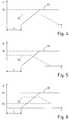
- the diesel oil flow rate Q C is increased until a target flow rate Q 0 is reached, which must be supplied at full rate in premix diesel oil supply mode and is defined by the control device 6 according to a control method (see figure 4 with this regard, in which the water flow rate QA is shown by a dash-and-dotted line and the diesel oil flow rate QC is shown by a solid line) .
- the diesel oil flow rate Q C is mixed in the static mixer 28 with the water flow rate Q A from the cleaning and cooling device 8.
- control device 6 acts on the adjustment valve 43 of the cleaning and cooling device 8 so as to progressively reduce the water flow rate Q A , until it is eliminated.
- the cooling water flow rate Q A supplied before starting to supply diesel oil allows to maintain the premix nozzles 31 at a relatively low temperature, in order to avoid the formation of solid carbonous deposits. Once the diesel oil flow rate is sufficiently high, the water flow rate may be either reduced or eliminated, because the diesel oil flow rate itself is capable of guaranteeing the cooling of the premix nozzles 31.
- the cooling and cleaning device 8 is activated during the passage from the diffusion diesel oil supply mode to the premix diesel oil supply mode.
- the transition from the diffusion diesel oil supply mode to the premix diesel oil supply mode further contemplates that the premix supply line 20 is gradually activated.
- the transition from the diffusion diesel oil supply mode to the premix diesel oil supply mode is carried out by gradually closing the adjustment valve 157 (see fig. 8 ) of the water cooling circuit 142 and gradually opening the adjustment valve 25 of the premix supply line 20 (with the stop valve 26 open), so as to generate an overlap of the cooling water flow rate and the diesel oil flow rate.
- This procedure allows to gradually switch from a 100% water flow supply to a 100% diesel oil flow supply. This gradual transition ensures that the diesel oil does not come into contact with excessively hot surfaces, thus avoiding the onset of undesired deposit formation in the premix nozzles 31 and in the manifold 27.
- the stop valves 145 are controlled by the control device 6.
- the thermocouple 147 detects the temperature in the high-pressure pipe 144 upstream of the stop valves 145.
- the detected temperature value is monitored in order to avoid an excessive overheating of the high-pressure pipe 144.
- such temperature value is supplied to the control device 6, which provides the activation of possible safety devices and measures (not shown).
- the air back flow mainly consists of hot air from the compressor 3, which flows in the annular pipe 34 of the burners 15.
- the air cleaning circuit 141 is activated between passing from diffusion diesel oil supply mode to premix diesel oil supply mode in order to clean the premix nozzles 31 and guarantee the correct operation thereof.
- the air cleaning circuit 141 is activated while diesel oil is supplied to the combustion chamber 4 through the diffusion nozzles 30.
- the air cleaning circuit 141 may be periodically activated during the gas supply mode to maintain clean the premix nozzles 31, often subject to obstruction. Specifically, the air cleaning circuit 141 is activated while supplying gas to the combustion chamber 4 through the gas nozzles 32.
- the water cooling circuit 142 comprises a water reserve 154 at a given temperature, preferably at ambient temperature, a high-pressure pump 155, a water filter 156, an adjustment valve 157 and a stop valve 158.
- the water cooling circuit 142 is connected to an end segment of the premix diesel oil supply circuit 20 through the static mixer 28.
- the cleaning and cooling device 8 is activated by the control device 6. Water flows in the fuel supply direction, i.e. from the water reserve 154 to the combustion chamber 4, through the water filter 156, the adjustment valve 157, the stop valve 158 and the static mixer 28.
- the opening of the stop valve 158 may be controlled either manually or by the control device 6 (as shown in figure 2 ).
- the water cooling circuit 142 is used in a transient step of activating the diesel oil supply mode, at the end of the cleaning cycle carried out by the air cleaning circuit 141. In this manner, the premix nozzles 31, just crossed by the hot air back flow, are cooled in order to prevent the formation of solid carbonous deposits.
- a pressurized water flow rate Q A is exclusively supplied for an interval of cooling time I C , so as to lower the temperature of the premix nozzles 31 under a threshold.
- the control device 6 acts on the adjustment valve 25 and on the stop valve 26 of the premix supply line 20 to supply a gradually increasing diesel oil flow rate Q C .
- the control device 6 intervenes on the adjustment valve to gradually reduce the cooling water flow rate Q A .
- the device 8 for cleaning diesel oil nozzles allows to carry out the transition from a gas supply to a diesel oil supply in a rapid, safe and effective manner without requiring the suspension of the combustion reaction inside the combustion chamber 4.
- the expansion chamber 152a into which the high-temperature air back flow leads contributes towards rapidly cooling the air back flow and, at the same time, towards considerably reducing the pressure thereof. In this manner, it is eliminated the severe risk that the liquid deposits conveyed by the air back flow, which often contain residual diesel oil, could catch fire inside the expansion chamber 152a, where diesel oil and air flow come into contact.
- the device 108 according to the present invention may also be installed in existing plants, and not only in newly constructed plants.
- the installation of the device 108 in newly constructed plants is extremely advantageous because the air cleaning circuit 141, if appropriately designed so as not to present subsequent circuit portions arranged at increasing heights, may also act as an emptying device. Indeed, at the end of combustion, the opening of the stop valves 145 determines the collection by effect of gravity in the expansion chamber 152a, and subsequently into the tank 151, of the residual fuel present in the manifold 27 and in the premix nozzles 31.
Landscapes
- Engineering & Computer Science (AREA)
- Chemical & Material Sciences (AREA)
- Combustion & Propulsion (AREA)
- Mechanical Engineering (AREA)
- General Engineering & Computer Science (AREA)
- Nozzles For Spraying Of Liquid Fuel (AREA)
Claims (14)
- Procédé d'approvisionnement d'une installation de turbine à gaz, comprenant les étapes suivantes :fournir un gaz aux buses de gaz (32) d'une chambre de combustion (4) de la turbine à gaz (11) ;fournir un combustible liquide aux buses de prémélange (31) de la turbine à gaz (11) à travers une canalisation de fourniture de prémélange (20) ; etcommuter entre l'étape de fourniture d'un gaz et l'étape de fourniture d'un combustible liquide ;où ladite étape de commutation, lors de la commutation du combustible gazeux au combustible liquide, comprend l'étape consistant à fournir un débit d'eau (QA) aux buses de prémélange (31) à travers la canalisation de fourniture de prémélange (20) pendant un temps de refroidissement (IC) en l'absence de combustible liquide, avant de fournir le combustible liquide ;caractérisé en ce que ladite étape de commutation comprend en outre les étapes suivantes :ajouter, après l'expiration dudit temps de refroidissement (IC), un flux de combustible liquide (QC) au débit d'eau (QA) ; etretirer une partie au moins du débit d'eau (QA), alors que l'on continue de fournir le flux de combustible liquide (QA).
- Procédé selon la revendication 1, où l'étape d'ajout comprend une étape consistant à augmenter progressivement le débit de combustible liquide (QC).
- Procédé selon la revendication 1 ou 2, où l'étape de retrait comprend une étape consistant à réduire progressivement le débit d'eau (QA).
- Procédé selon l'une quelconque des revendications précédentes, où l'étape de retrait est exécutée lorsque le débit de combustible liquide (QC) a atteint un débit cible (Q0).
- Procédé selon l'une quelconque des revendications 1 à 3, où l'étape de retrait est exécutée lorsque le débit de combustible liquide (QC) a atteint un pourcentage seuil d'un débit cible (Q0).
- Procédé selon l'une quelconque des revendications 1 à 5, où l'étape de retrait comprend une étape consistant à supprimer le débit d'eau (QA).
- Procédé selon l'une quelconque des revendications précédentes, où l'étape de retrait comprend une étape consistant à maintenir un débit d'eau résiduel (QR).
- Procédé selon l'une quelconque des revendications précédentes, où le temps de refroidissement (IC) est tel que le débit (QA) réduit la température des buses de prémélange (31) sous un seuil de température.
- Procédé selon l'une quelconque des revendications précédentes, comprenant l'étape de nettoyage des buses de prémélange (31) avant l'étape de fourniture d'un combustible liquide aux buses de prémélange (31).
- Procédé selon la revendication 9, où l'étape de nettoyage des buses de prémélange (31), comprend l'utilisation du débit d'eau (QA).
- Procédé selon la revendication 9, où l'étape de nettoyage des buses de prémélange (31) comprend l'utilisation d'un flux de retour d'air provenant d'une chambre de combustion (4) de l'installation (1).
- Procédé selon l'une quelconque des revendications précédentes, où le combustible liquide est un combustible diesel.
- Procédé selon l'une quelconque des revendications précédentes, comprenant l'étape de nettoyage des buses de prémélange (31) par un flux de retour d'air, tandis qu'un processus de combustion est en cours dans la chambre de combustion (4).
- Installation de turbine à gaz, comprenant :une turbine à gaz (11) ;une chambre de combustion (4), accouplée à la turbine à gaz (11), et présentant une pluralité de brûleurs (15) dotés de buses de prémélange correspondantes (31) ;un circuit de fourniture de gaz (16), destiné à fournir le gaz aux buses de gaz (32) ;un circuit de fourniture de combustible liquide (17), présentant une canalisation de fourniture de prémélange (20) destinée à fournir le combustible liquide aux buses de prémélange (31) ;un dispositif de refroidissement (8 ; 108), destiné à fournir un débit d'eau (QA) aux buses de prémélange (31) à travers la canalisation de fourniture de prémélange (20) ;des moyens de commande (6, 25, 26, 43, 44; 6, 25, 26, 157, 158), destinés à actionner sélectivement le circuit de fourniture de gaz (16) et le circuit de fourniture de combustible liquide (17) ;où les moyens de commande sont configurés pour commander le circuit de fourniture de combustible liquide (17) et le dispositif de refroidissement (8 ; 108) afin de fournir un débit d'eau (QA) aux buses de prémélange (31) à travers la canalisation de fourniture de prémélange (20) pendant un temps de refroidissement (IC) en l'absence de combustible liquide, avant d'actionner le circuit de fourniture de combustible liquide (17) lors d'une commutation du combustible gazeux au combustible liquide, caractérisé en ce que les moyens de commande sont configurés en outre pour commander le circuit de fourniture de combustible liquide (17) et le dispositif de refroidissement (8 ; 108) afin d'actionner le circuit de fourniture de combustible liquide (17) après l'expiration dudit temps de refroidissement (IC), tandis que le dispositif de refroidissement (8 ; 108) fournit le débit d'eau (QA), et afin de retirer une partie au moins du débit d'eau (QA), tandis que l'on continue de fournir le débit de combustible liquide (QC).
Applications Claiming Priority (2)
| Application Number | Priority Date | Filing Date | Title |
|---|---|---|---|
| ITMI2008A002263A IT1392335B1 (it) | 2008-12-19 | 2008-12-19 | Metodo e dispositivo per pulire ugelli gasolio di un bruciatore |
| PCT/IT2009/000039 WO2010070692A1 (fr) | 2008-12-19 | 2009-02-06 | Procédé de fourniture d'une installation de turbine à gaz et installation de turbine à gaz |
Publications (2)
| Publication Number | Publication Date |
|---|---|
| EP2379944A1 EP2379944A1 (fr) | 2011-10-26 |
| EP2379944B1 true EP2379944B1 (fr) | 2019-08-07 |
Family
ID=40887851
Family Applications (1)
| Application Number | Title | Priority Date | Filing Date |
|---|---|---|---|
| EP09833087.1A Active EP2379944B1 (fr) | 2008-12-19 | 2009-02-06 | Procede de fourniture d'une installation de turbine a gaz et installation de turbine a gaz |
Country Status (2)
| Country | Link |
|---|---|
| EP (1) | EP2379944B1 (fr) |
| WO (1) | WO2010070692A1 (fr) |
Families Citing this family (4)
| Publication number | Priority date | Publication date | Assignee | Title |
|---|---|---|---|---|
| CH705965A1 (de) * | 2012-01-09 | 2013-07-15 | Alstom Technology Ltd | Verfahren zum Betrieb einer Gasturbine. |
| US8991190B2 (en) * | 2012-01-31 | 2015-03-31 | General Electric Company | Fuel nozzle staging with water flowing prior to fuel in a main fuel circuit during start-up |
| ITMI20131816A1 (it) * | 2013-10-31 | 2015-05-01 | Ansaldo Energia Spa | Iniettore a lancia a doppio ugello per turbina a gas, impianto a turbina a gas e metodo di alimentazione di una turbina a gas |
| FR3072126B1 (fr) * | 2017-10-10 | 2022-04-22 | Ge Energy Products France Snc | Systemes d'alimentation en combustible liquide d'un systeme de combustion, notamment d'une turbine a gaz, comprenant un dispositif de generation d'une emulsion et de repartition du debit d'emulsion |
Citations (1)
| Publication number | Priority date | Publication date | Assignee | Title |
|---|---|---|---|---|
| EP0952317A2 (fr) * | 1998-04-21 | 1999-10-27 | Mitsubishi Heavy Industries, Ltd. | Système de purge pour l'alimentation en carburant d'une turbine à gaz |
Family Cites Families (5)
| Publication number | Priority date | Publication date | Assignee | Title |
|---|---|---|---|---|
| US4110973A (en) * | 1977-01-24 | 1978-09-05 | Energy Services Inc. | Water injection system for industrial gas turbine engine |
| US5404711A (en) * | 1993-06-10 | 1995-04-11 | Solar Turbines Incorporated | Dual fuel injector nozzle for use with a gas turbine engine |
| US6145294A (en) * | 1998-04-09 | 2000-11-14 | General Electric Co. | Liquid fuel and water injection purge system for a gas turbine |
| DE102007015311A1 (de) * | 2006-03-31 | 2007-10-04 | Alstom Technology Ltd. | Verfahren zum Betrieb einer Gasturbine |
| WO2008125907A2 (fr) * | 2006-10-26 | 2008-10-23 | Rolls-Royce Power Engineering Plc | Procédé et appareil d'isolation de passages de combustible inactifs |
-
2009
- 2009-02-06 WO PCT/IT2009/000039 patent/WO2010070692A1/fr not_active Ceased
- 2009-02-06 EP EP09833087.1A patent/EP2379944B1/fr active Active
Patent Citations (1)
| Publication number | Priority date | Publication date | Assignee | Title |
|---|---|---|---|---|
| EP0952317A2 (fr) * | 1998-04-21 | 1999-10-27 | Mitsubishi Heavy Industries, Ltd. | Système de purge pour l'alimentation en carburant d'une turbine à gaz |
Also Published As
| Publication number | Publication date |
|---|---|
| WO2010070692A1 (fr) | 2010-06-24 |
| EP2379944A1 (fr) | 2011-10-26 |
Similar Documents
| Publication | Publication Date | Title |
|---|---|---|
| KR101398381B1 (ko) | 가스 터빈 연소기의 연료 공급 계통 및 가스 터빈 연소기의 연료 공급 방법 | |
| CN1963159B (zh) | 用于燃气轮机氮气清洗系统的方法和设备 | |
| US9239013B2 (en) | Combustion turbine purge system and method of assembling same | |
| EP0949454B1 (fr) | Système de purge pour dispositif d'injection de carburant liquide et d'eau d'une turbine à gaz | |
| JP4246874B2 (ja) | 多機能付加型水噴射マニホールド及びその操作方法 | |
| US9410486B2 (en) | System and method for washing and purging the liquid fuel system of a turbine with water | |
| EP3147484B1 (fr) | Procédé et système de transfert fiable de l'état gazeux à l'état liquide | |
| TWI880740B (zh) | 發電設備 | |
| CN102308066A (zh) | 用于冲洗燃气轮机的燃料系统的部段的方法 | |
| WO2010070692A1 (fr) | Procédé de fourniture d'une installation de turbine à gaz et installation de turbine à gaz | |
| RU2610371C2 (ru) | Система продувки топлива и способ продувки топлива (варианты) | |
| CN106439894B (zh) | 一种燃机及其启动节能控制方法 | |
| RU2541487C2 (ru) | Способ эксплуатации системы подачи топлива для теплового двигателя | |
| CN113551914B (zh) | 一种燃油喷嘴试验件防积碳结构及方法 | |
| EP2199676A1 (fr) | Procédé et dispositif de nettoyage des buses à huile d'un brûleur | |
| US8128862B2 (en) | Blast furnace gas burning facility and method for operating the same | |
| CN212157208U (zh) | 一种安全型有机废气蓄热催化氧化装置 | |
| CN114810358A (zh) | 燃气轮机低排放双燃料系统及其控制方法 | |
| CN117065465B (zh) | 一种除尘、脱硝、脱硫一体化装置的检查及操作方法 | |
| US11905883B2 (en) | Fuel supply circuit for a combustion chamber of a turbomachine | |
| CN115646911B (zh) | 一种压气机离线清洗系统 | |
| CN116066263B (zh) | 一种氨燃料管路系统及其控制方法 | |
| CN222703095U (zh) | 一种燃驱压缩机燃料气切换装置 | |
| CN221801849U (zh) | 一种燃烧室 | |
| KR20090126800A (ko) | 이중주입 방식에 의한 배가스에 함유된 이산화질소 제거장치 및 이를 이용한 제거 방법 |
Legal Events
| Date | Code | Title | Description |
|---|---|---|---|
| PUAI | Public reference made under article 153(3) epc to a published international application that has entered the european phase |
Free format text: ORIGINAL CODE: 0009012 |
|
| 17P | Request for examination filed |
Effective date: 20110719 |
|
| AK | Designated contracting states |
Kind code of ref document: A1 Designated state(s): AT BE BG CH CY CZ DE DK EE ES FI FR GB GR HR HU IE IS IT LI LT LU LV MC MK MT NL NO PL PT RO SE SI SK TR |
|
| DAX | Request for extension of the european patent (deleted) | ||
| 17Q | First examination report despatched |
Effective date: 20150803 |
|
| STAA | Information on the status of an ep patent application or granted ep patent |
Free format text: STATUS: EXAMINATION IS IN PROGRESS |
|
| GRAP | Despatch of communication of intention to grant a patent |
Free format text: ORIGINAL CODE: EPIDOSNIGR1 |
|
| STAA | Information on the status of an ep patent application or granted ep patent |
Free format text: STATUS: GRANT OF PATENT IS INTENDED |
|
| INTG | Intention to grant announced |
Effective date: 20190212 |
|
| GRAS | Grant fee paid |
Free format text: ORIGINAL CODE: EPIDOSNIGR3 |
|
| GRAJ | Information related to disapproval of communication of intention to grant by the applicant or resumption of examination proceedings by the epo deleted |
Free format text: ORIGINAL CODE: EPIDOSDIGR1 |
|
| GRAL | Information related to payment of fee for publishing/printing deleted |
Free format text: ORIGINAL CODE: EPIDOSDIGR3 |
|
| STAA | Information on the status of an ep patent application or granted ep patent |
Free format text: STATUS: EXAMINATION IS IN PROGRESS |
|
| GRAR | Information related to intention to grant a patent recorded |
Free format text: ORIGINAL CODE: EPIDOSNIGR71 |
|
| STAA | Information on the status of an ep patent application or granted ep patent |
Free format text: STATUS: GRANT OF PATENT IS INTENDED |
|
| GRAA | (expected) grant |
Free format text: ORIGINAL CODE: 0009210 |
|
| STAA | Information on the status of an ep patent application or granted ep patent |
Free format text: STATUS: THE PATENT HAS BEEN GRANTED |
|
| INTC | Intention to grant announced (deleted) | ||
| INTG | Intention to grant announced |
Effective date: 20190625 |
|
| AK | Designated contracting states |
Kind code of ref document: B1 Designated state(s): AT BE BG CH CY CZ DE DK EE ES FI FR GB GR HR HU IE IS IT LI LT LU LV MC MK MT NL NO PL PT RO SE SI SK TR |
|
| REG | Reference to a national code |
Ref country code: GB Ref legal event code: FG4D |
|
| REG | Reference to a national code |
Ref country code: CH Ref legal event code: EP Ref country code: AT Ref legal event code: REF Ref document number: 1164452 Country of ref document: AT Kind code of ref document: T Effective date: 20190815 |
|
| REG | Reference to a national code |
Ref country code: DE Ref legal event code: R096 Ref document number: 602009059398 Country of ref document: DE |
|
| REG | Reference to a national code |
Ref country code: IE Ref legal event code: FG4D |
|
| REG | Reference to a national code |
Ref country code: NL Ref legal event code: MP Effective date: 20190807 |
|
| REG | Reference to a national code |
Ref country code: LT Ref legal event code: MG4D |
|
| PG25 | Lapsed in a contracting state [announced via postgrant information from national office to epo] |
Ref country code: SE Free format text: LAPSE BECAUSE OF FAILURE TO SUBMIT A TRANSLATION OF THE DESCRIPTION OR TO PAY THE FEE WITHIN THE PRESCRIBED TIME-LIMIT Effective date: 20190807 Ref country code: PT Free format text: LAPSE BECAUSE OF FAILURE TO SUBMIT A TRANSLATION OF THE DESCRIPTION OR TO PAY THE FEE WITHIN THE PRESCRIBED TIME-LIMIT Effective date: 20191209 Ref country code: HR Free format text: LAPSE BECAUSE OF FAILURE TO SUBMIT A TRANSLATION OF THE DESCRIPTION OR TO PAY THE FEE WITHIN THE PRESCRIBED TIME-LIMIT Effective date: 20190807 Ref country code: LT Free format text: LAPSE BECAUSE OF FAILURE TO SUBMIT A TRANSLATION OF THE DESCRIPTION OR TO PAY THE FEE WITHIN THE PRESCRIBED TIME-LIMIT Effective date: 20190807 Ref country code: NL Free format text: LAPSE BECAUSE OF FAILURE TO SUBMIT A TRANSLATION OF THE DESCRIPTION OR TO PAY THE FEE WITHIN THE PRESCRIBED TIME-LIMIT Effective date: 20190807 Ref country code: FI Free format text: LAPSE BECAUSE OF FAILURE TO SUBMIT A TRANSLATION OF THE DESCRIPTION OR TO PAY THE FEE WITHIN THE PRESCRIBED TIME-LIMIT Effective date: 20190807 Ref country code: NO Free format text: LAPSE BECAUSE OF FAILURE TO SUBMIT A TRANSLATION OF THE DESCRIPTION OR TO PAY THE FEE WITHIN THE PRESCRIBED TIME-LIMIT Effective date: 20191107 Ref country code: BG Free format text: LAPSE BECAUSE OF FAILURE TO SUBMIT A TRANSLATION OF THE DESCRIPTION OR TO PAY THE FEE WITHIN THE PRESCRIBED TIME-LIMIT Effective date: 20191107 |
|
| REG | Reference to a national code |
Ref country code: AT Ref legal event code: MK05 Ref document number: 1164452 Country of ref document: AT Kind code of ref document: T Effective date: 20190807 |
|
| PG25 | Lapsed in a contracting state [announced via postgrant information from national office to epo] |
Ref country code: ES Free format text: LAPSE BECAUSE OF FAILURE TO SUBMIT A TRANSLATION OF THE DESCRIPTION OR TO PAY THE FEE WITHIN THE PRESCRIBED TIME-LIMIT Effective date: 20190807 Ref country code: IS Free format text: LAPSE BECAUSE OF FAILURE TO SUBMIT A TRANSLATION OF THE DESCRIPTION OR TO PAY THE FEE WITHIN THE PRESCRIBED TIME-LIMIT Effective date: 20191207 Ref country code: LV Free format text: LAPSE BECAUSE OF FAILURE TO SUBMIT A TRANSLATION OF THE DESCRIPTION OR TO PAY THE FEE WITHIN THE PRESCRIBED TIME-LIMIT Effective date: 20190807 Ref country code: GR Free format text: LAPSE BECAUSE OF FAILURE TO SUBMIT A TRANSLATION OF THE DESCRIPTION OR TO PAY THE FEE WITHIN THE PRESCRIBED TIME-LIMIT Effective date: 20191108 |
|
| PG25 | Lapsed in a contracting state [announced via postgrant information from national office to epo] |
Ref country code: TR Free format text: LAPSE BECAUSE OF FAILURE TO SUBMIT A TRANSLATION OF THE DESCRIPTION OR TO PAY THE FEE WITHIN THE PRESCRIBED TIME-LIMIT Effective date: 20190807 |
|
| PG25 | Lapsed in a contracting state [announced via postgrant information from national office to epo] |
Ref country code: RO Free format text: LAPSE BECAUSE OF FAILURE TO SUBMIT A TRANSLATION OF THE DESCRIPTION OR TO PAY THE FEE WITHIN THE PRESCRIBED TIME-LIMIT Effective date: 20190807 Ref country code: AT Free format text: LAPSE BECAUSE OF FAILURE TO SUBMIT A TRANSLATION OF THE DESCRIPTION OR TO PAY THE FEE WITHIN THE PRESCRIBED TIME-LIMIT Effective date: 20190807 Ref country code: DK Free format text: LAPSE BECAUSE OF FAILURE TO SUBMIT A TRANSLATION OF THE DESCRIPTION OR TO PAY THE FEE WITHIN THE PRESCRIBED TIME-LIMIT Effective date: 20190807 Ref country code: EE Free format text: LAPSE BECAUSE OF FAILURE TO SUBMIT A TRANSLATION OF THE DESCRIPTION OR TO PAY THE FEE WITHIN THE PRESCRIBED TIME-LIMIT Effective date: 20190807 Ref country code: PL Free format text: LAPSE BECAUSE OF FAILURE TO SUBMIT A TRANSLATION OF THE DESCRIPTION OR TO PAY THE FEE WITHIN THE PRESCRIBED TIME-LIMIT Effective date: 20190807 |
|
| PG25 | Lapsed in a contracting state [announced via postgrant information from national office to epo] |
Ref country code: CZ Free format text: LAPSE BECAUSE OF FAILURE TO SUBMIT A TRANSLATION OF THE DESCRIPTION OR TO PAY THE FEE WITHIN THE PRESCRIBED TIME-LIMIT Effective date: 20190807 Ref country code: SK Free format text: LAPSE BECAUSE OF FAILURE TO SUBMIT A TRANSLATION OF THE DESCRIPTION OR TO PAY THE FEE WITHIN THE PRESCRIBED TIME-LIMIT Effective date: 20190807 Ref country code: IS Free format text: LAPSE BECAUSE OF FAILURE TO SUBMIT A TRANSLATION OF THE DESCRIPTION OR TO PAY THE FEE WITHIN THE PRESCRIBED TIME-LIMIT Effective date: 20200224 |
|
| REG | Reference to a national code |
Ref country code: DE Ref legal event code: R097 Ref document number: 602009059398 Country of ref document: DE |
|
| PLBE | No opposition filed within time limit |
Free format text: ORIGINAL CODE: 0009261 |
|
| STAA | Information on the status of an ep patent application or granted ep patent |
Free format text: STATUS: NO OPPOSITION FILED WITHIN TIME LIMIT |
|
| PG2D | Information on lapse in contracting state deleted |
Ref country code: IS |
|
| 26N | No opposition filed |
Effective date: 20200603 |
|
| PG25 | Lapsed in a contracting state [announced via postgrant information from national office to epo] |
Ref country code: SI Free format text: LAPSE BECAUSE OF FAILURE TO SUBMIT A TRANSLATION OF THE DESCRIPTION OR TO PAY THE FEE WITHIN THE PRESCRIBED TIME-LIMIT Effective date: 20190807 |
|
| REG | Reference to a national code |
Ref country code: CH Ref legal event code: PL |
|
| GBPC | Gb: european patent ceased through non-payment of renewal fee |
Effective date: 20200206 |
|
| REG | Reference to a national code |
Ref country code: BE Ref legal event code: MM Effective date: 20200229 |
|
| PG25 | Lapsed in a contracting state [announced via postgrant information from national office to epo] |
Ref country code: LU Free format text: LAPSE BECAUSE OF NON-PAYMENT OF DUE FEES Effective date: 20200206 Ref country code: MC Free format text: LAPSE BECAUSE OF FAILURE TO SUBMIT A TRANSLATION OF THE DESCRIPTION OR TO PAY THE FEE WITHIN THE PRESCRIBED TIME-LIMIT Effective date: 20190807 |
|
| PG25 | Lapsed in a contracting state [announced via postgrant information from national office to epo] |
Ref country code: LI Free format text: LAPSE BECAUSE OF NON-PAYMENT OF DUE FEES Effective date: 20200229 Ref country code: CH Free format text: LAPSE BECAUSE OF NON-PAYMENT OF DUE FEES Effective date: 20200229 |
|
| PG25 | Lapsed in a contracting state [announced via postgrant information from national office to epo] |
Ref country code: FR Free format text: LAPSE BECAUSE OF NON-PAYMENT OF DUE FEES Effective date: 20200229 Ref country code: IE Free format text: LAPSE BECAUSE OF NON-PAYMENT OF DUE FEES Effective date: 20200206 Ref country code: GB Free format text: LAPSE BECAUSE OF NON-PAYMENT OF DUE FEES Effective date: 20200206 |
|
| PG25 | Lapsed in a contracting state [announced via postgrant information from national office to epo] |
Ref country code: BE Free format text: LAPSE BECAUSE OF NON-PAYMENT OF DUE FEES Effective date: 20200229 |
|
| PG25 | Lapsed in a contracting state [announced via postgrant information from national office to epo] |
Ref country code: MT Free format text: LAPSE BECAUSE OF FAILURE TO SUBMIT A TRANSLATION OF THE DESCRIPTION OR TO PAY THE FEE WITHIN THE PRESCRIBED TIME-LIMIT Effective date: 20190807 Ref country code: CY Free format text: LAPSE BECAUSE OF FAILURE TO SUBMIT A TRANSLATION OF THE DESCRIPTION OR TO PAY THE FEE WITHIN THE PRESCRIBED TIME-LIMIT Effective date: 20190807 |
|
| PG25 | Lapsed in a contracting state [announced via postgrant information from national office to epo] |
Ref country code: MK Free format text: LAPSE BECAUSE OF FAILURE TO SUBMIT A TRANSLATION OF THE DESCRIPTION OR TO PAY THE FEE WITHIN THE PRESCRIBED TIME-LIMIT Effective date: 20190807 |
|
| PGFP | Annual fee paid to national office [announced via postgrant information from national office to epo] |
Ref country code: DE Payment date: 20240216 Year of fee payment: 16 |
|
| PGFP | Annual fee paid to national office [announced via postgrant information from national office to epo] |
Ref country code: IT Payment date: 20240229 Year of fee payment: 16 |
|
| P01 | Opt-out of the competence of the unified patent court (upc) registered |
Effective date: 20240430 |
|
| REG | Reference to a national code |
Ref country code: DE Ref legal event code: R119 Ref document number: 602009059398 Country of ref document: DE |
|
| PG25 | Lapsed in a contracting state [announced via postgrant information from national office to epo] |
Ref country code: DE Free format text: LAPSE BECAUSE OF NON-PAYMENT OF DUE FEES Effective date: 20250902 |
|
| PG25 | Lapsed in a contracting state [announced via postgrant information from national office to epo] |
Ref country code: IT Free format text: LAPSE BECAUSE OF NON-PAYMENT OF DUE FEES Effective date: 20250206 |