EP2379957B1 - Anlage zur erzeugung von elektrischer energie mittels fotovoltaischer elemente - Google Patents
Anlage zur erzeugung von elektrischer energie mittels fotovoltaischer elemente Download PDFInfo
- Publication number
- EP2379957B1 EP2379957B1 EP10708689.4A EP10708689A EP2379957B1 EP 2379957 B1 EP2379957 B1 EP 2379957B1 EP 10708689 A EP10708689 A EP 10708689A EP 2379957 B1 EP2379957 B1 EP 2379957B1
- Authority
- EP
- European Patent Office
- Prior art keywords
- supporting
- support
- cable
- beams
- pivoting
- Prior art date
- Legal status (The legal status is an assumption and is not a legal conclusion. Google has not performed a legal analysis and makes no representation as to the accuracy of the status listed.)
- Not-in-force
Links
- 241000196324 Embryophyta Species 0.000 description 4
- 241000209035 Ilex Species 0.000 description 3
- 230000015572 biosynthetic process Effects 0.000 description 1
- 210000002023 somite Anatomy 0.000 description 1
Images




Classifications
-
- H—ELECTRICITY
- H10—SEMICONDUCTOR DEVICES; ELECTRIC SOLID-STATE DEVICES NOT OTHERWISE PROVIDED FOR
- H10F—INORGANIC SEMICONDUCTOR DEVICES SENSITIVE TO INFRARED RADIATION, LIGHT, ELECTROMAGNETIC RADIATION OF SHORTER WAVELENGTH OR CORPUSCULAR RADIATION
- H10F19/00—Integrated devices, or assemblies of multiple devices, comprising at least one photovoltaic cell covered by group H10F10/00, e.g. photovoltaic modules
-
- H—ELECTRICITY
- H02—GENERATION; CONVERSION OR DISTRIBUTION OF ELECTRIC POWER
- H02S—GENERATION OF ELECTRIC POWER BY CONVERSION OF INFRARED RADIATION, VISIBLE LIGHT OR ULTRAVIOLET LIGHT, e.g. USING PHOTOVOLTAIC [PV] MODULES
- H02S20/00—Supporting structures for PV modules
- H02S20/10—Supporting structures directly fixed to the ground
-
- F—MECHANICAL ENGINEERING; LIGHTING; HEATING; WEAPONS; BLASTING
- F24—HEATING; RANGES; VENTILATING
- F24S—SOLAR HEAT COLLECTORS; SOLAR HEAT SYSTEMS
- F24S30/00—Arrangements for moving or orienting solar heat collector modules
- F24S30/40—Arrangements for moving or orienting solar heat collector modules for rotary movement
- F24S30/45—Arrangements for moving or orienting solar heat collector modules for rotary movement with two rotation axes
- F24S30/452—Vertical primary axis
-
- H—ELECTRICITY
- H02—GENERATION; CONVERSION OR DISTRIBUTION OF ELECTRIC POWER
- H02S—GENERATION OF ELECTRIC POWER BY CONVERSION OF INFRARED RADIATION, VISIBLE LIGHT OR ULTRAVIOLET LIGHT, e.g. USING PHOTOVOLTAIC [PV] MODULES
- H02S20/00—Supporting structures for PV modules
-
- H—ELECTRICITY
- H02—GENERATION; CONVERSION OR DISTRIBUTION OF ELECTRIC POWER
- H02S—GENERATION OF ELECTRIC POWER BY CONVERSION OF INFRARED RADIATION, VISIBLE LIGHT OR ULTRAVIOLET LIGHT, e.g. USING PHOTOVOLTAIC [PV] MODULES
- H02S20/00—Supporting structures for PV modules
- H02S20/30—Supporting structures being movable or adjustable, e.g. for angle adjustment
-
- H—ELECTRICITY
- H02—GENERATION; CONVERSION OR DISTRIBUTION OF ELECTRIC POWER
- H02S—GENERATION OF ELECTRIC POWER BY CONVERSION OF INFRARED RADIATION, VISIBLE LIGHT OR ULTRAVIOLET LIGHT, e.g. USING PHOTOVOLTAIC [PV] MODULES
- H02S20/00—Supporting structures for PV modules
- H02S20/30—Supporting structures being movable or adjustable, e.g. for angle adjustment
- H02S20/32—Supporting structures being movable or adjustable, e.g. for angle adjustment specially adapted for solar tracking
-
- F—MECHANICAL ENGINEERING; LIGHTING; HEATING; WEAPONS; BLASTING
- F24—HEATING; RANGES; VENTILATING
- F24S—SOLAR HEAT COLLECTORS; SOLAR HEAT SYSTEMS
- F24S25/00—Arrangement of stationary mountings or supports for solar heat collector modules
- F24S2025/01—Special support components; Methods of use
- F24S2025/017—Tensioning means
-
- F—MECHANICAL ENGINEERING; LIGHTING; HEATING; WEAPONS; BLASTING
- F24—HEATING; RANGES; VENTILATING
- F24S—SOLAR HEAT COLLECTORS; SOLAR HEAT SYSTEMS
- F24S30/00—Arrangements for moving or orienting solar heat collector modules
- F24S2030/10—Special components
- F24S2030/13—Transmissions
- F24S2030/133—Transmissions in the form of flexible elements, e.g. belts, chains, ropes
-
- F—MECHANICAL ENGINEERING; LIGHTING; HEATING; WEAPONS; BLASTING
- F24—HEATING; RANGES; VENTILATING
- F24S—SOLAR HEAT COLLECTORS; SOLAR HEAT SYSTEMS
- F24S30/00—Arrangements for moving or orienting solar heat collector modules
- F24S2030/10—Special components
- F24S2030/13—Transmissions
- F24S2030/136—Transmissions for moving several solar collectors by common transmission elements
-
- Y—GENERAL TAGGING OF NEW TECHNOLOGICAL DEVELOPMENTS; GENERAL TAGGING OF CROSS-SECTIONAL TECHNOLOGIES SPANNING OVER SEVERAL SECTIONS OF THE IPC; TECHNICAL SUBJECTS COVERED BY FORMER USPC CROSS-REFERENCE ART COLLECTIONS [XRACs] AND DIGESTS
- Y02—TECHNOLOGIES OR APPLICATIONS FOR MITIGATION OR ADAPTATION AGAINST CLIMATE CHANGE
- Y02E—REDUCTION OF GREENHOUSE GAS [GHG] EMISSIONS, RELATED TO ENERGY GENERATION, TRANSMISSION OR DISTRIBUTION
- Y02E10/00—Energy generation through renewable energy sources
- Y02E10/40—Solar thermal energy, e.g. solar towers
- Y02E10/47—Mountings or tracking
-
- Y—GENERAL TAGGING OF NEW TECHNOLOGICAL DEVELOPMENTS; GENERAL TAGGING OF CROSS-SECTIONAL TECHNOLOGIES SPANNING OVER SEVERAL SECTIONS OF THE IPC; TECHNICAL SUBJECTS COVERED BY FORMER USPC CROSS-REFERENCE ART COLLECTIONS [XRACs] AND DIGESTS
- Y02—TECHNOLOGIES OR APPLICATIONS FOR MITIGATION OR ADAPTATION AGAINST CLIMATE CHANGE
- Y02E—REDUCTION OF GREENHOUSE GAS [GHG] EMISSIONS, RELATED TO ENERGY GENERATION, TRANSMISSION OR DISTRIBUTION
- Y02E10/00—Energy generation through renewable energy sources
- Y02E10/50—Photovoltaic [PV] energy
Definitions
- the subject invention relates to a system for the production of electrical energy by means of photovoltaic elements, which are based on a by ropes and control cables or the like. formed support structure and which are pivotable about at least approximately vertically aligned axes, whereby they are the East-West movement of the sun trackable, and further pivoted about at least approximately horizontally aligned axes, whereby they are adjustable to the height of the sun, the photovoltaic elements on a plurality of mutually at least approximately parallel and approximately horizontally oriented support beam or the like. are fixed, wherein the support beam or the like. at one of its two ends to a support cable or the like.
- Such a plant for the production of electrical energy is from the JP 2003-32-9963 A known.
- a plant for the production of electrical energy by means of photovoltaic elements which are based on a particular by ropes and control cables or the like.
- formed support structure which are pivotable about at least approximately vertically aligned axes, whereby they are the East-West movement of the sun trackable and which are further pivotable about at least approximately horizontally oriented axes, whereby they are adjustable to the height of the sun, is out of the WO 2008/064382 A2 and the WO 2006/130892 A1 known.
- the individual photovoltaic elements are formed as rectangular plates which are formed with projecting from both ends of the axle journals, which are articulated at their free ends to control cables, which are guided over deflection pulleys and closed in itself.
- the two strands of a first of these two control cables are movable in a vertical plane around two deflecting disks oriented in a vertical plane and the two strands of the second of these two control cables are movable about two deflecting disks oriented in a horizontal plane in a horizontal plane, wherein the respective one another associated dreams are mutually adjustable.
- the photovoltaic elements are mounted so as to be pivotable about vertically aligned axes, whereby they can be tracked during an adjustment of the second actuating cable of the east-west movement of the sun.
- the photovoltaic elements are pivotally mounted about horizontal axes, whereby they by adjusting the first Stellseiles the level of the sun are trackable. Since each photovoltaic element is articulated to two differently oriented control cables and separate drives are provided for all control cables, this known system has a very complex structural design.
- the subject invention is therefore an object of the invention to provide a system for generating electrical energy using a variety of adjustable to the respective position of the sun photovoltaic elements, in which the prior art adhering disadvantage is avoided, which therefore compared to the known constructive Design has a much simplified structure.
- This object is achieved erfingdungsloom that at least one of the support beams on a support column, support post or the like. relative to this about its horizontally oriented axis rotatable and about a vertical longitudinal axis of the support column, support post or the like. is mounted pivotably, and that further on one of the support columns or the like. on the one hand, a pivoting device and on the other hand, a rotating device are provided for this support beam.
- the pivoting and rotating device is provided by a carrying and setting cable or the like provided with two approximately parallel runs. formed, which is adjustable in its longitudinal direction and whose two strands are mutually adjustable. Furthermore, there are preferably between the two strands of the support and control cable to these hinged cross braces, which with the associated ends of the support beams or the like. are firmly connected.
- At least one of the support beams or the like. is on a support column, support post or the like. relative to this pivotally mounted and rotatably mounted, wherein further on the support column on the one hand a pivoting device and on the other hand, a rotating device for this support beam or the like. are provided. Furthermore, preferably the pivoting movements and the rotational movements of the support column, support post or the like. mounted support beam on the longitudinal adjustment of the support and control cable and the opposite adjustment of the two strands of coupled with this support beam support and control cable to the other support beams or the like. transferable.
- a system according to the invention for the production of electrical energy or the like at the two ends of the particular by support and control cables.
- formed supporting structure in each case a support column, support bracket or the like. provided at which the support beam located there or the like. are mounted pivotably or rotatably, at least one of the two support columns, support posts or the like. with drives for the pivoting and for the rotation of the associated support beam or the like. trained and are the stringers or the like.
- a first support cable about an at least approximately vertical axis pivotable and rotatably mounted about its longitudinal axis and by means of the other ends associated supporting and actuating cable with each other on pivoting about at least approximately vertical axes and rotation about their Longitudinal axes coupled.
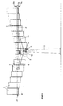
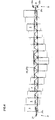
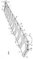
- the in the FIG.1 to FIG.3 illustrated plant for the production of electrical energy by means of photovoltaic elements has two support columns 1 and 1b, on which a support structure 2 for photovoltaic elements 3 is located.
- the structure 2 consists of a support cable 21 and one of them at a distance, to the support cable 21 parallel aligned support and control cable 22 with two runs 22a and 22b, wherein between the support cable 21 and the support and control cable 22 stringers 20, 20a and 20b are for the structure 2 of the photovoltaic elements 3, which are hinged to the support cable 21 and to the support and control cable 22.
- the support beam 20 and the support beam 20b are pivotally mounted on the support columns 1 and 1b, whereby the support structure 2 is supported by the support columns 1 and 1b.
- the support beams 20a are in contrast carried by the support cable 21 and the support and control cable 22. Groups of a plurality of photovoltaic elements 3 are attached to the support beams 20 and 20a, respectively.
- the two strands 22a and 22b of the support and positioning cable 22, which are arranged vertically one above the other, are connected to each other by means of transverse struts 23 and 23a, which are hinged to the two strands 22a and 22b of the support and control cable 22, for example by means of ball joints.
- the support cables 21 associated ends of the support beams 20 and 20a are rotatably mounted on the support cable 21 on the one hand about a respective vertical axis pivotable about the longitudinal axes of the support beams 20 and 20a.
- the other ends of the supporting beams 20 and 20a are rigidly connected to the transverse struts 23 and 23a, these ends being located approximately in the middle between the two strands 22a and 22b of the supporting and adjusting cable 22.
- the carrying cable 21 and the carrying and adjusting cable 22 are connected to one another by means of the supporting beam 20 b, wherein the beam 20 b is articulated to a transverse strut 23 b which is located between the two runs 22 a and 22 b.
- a first servo motor 4 by which the support beam 20 is pivotable about a vertical axis in a horizontal plane. Furthermore, located on the support column 1, a second servo motor 5 through which the support beam 20 is rotatable about its horizontally oriented axis.
- FIG.3 located on the drive shaft of the motor 4, a pinion 41 which cooperates with a rotatable about a vertical axis gear 42.
- a two-armed adjusting bar 43 is fixedly connected, which is pivotable about the vertical axis of rotation of the gear 42 and which is fixedly connected to the support beam 20. Since the left end of the support beam 20 is pivotally mounted on the associated support cable 21 about the vertical axis of rotation, thereby the support beam 20 can be pivoted in a horizontal plane.
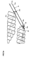
- the support beams 20 and 20a may be formed as a framework, which is provided at its two ends with support pins 20c, which are articulated at the left end to the support cable 21 and are connected at the right end to the transverse struts 23 and 23a, the ends thereof are hinged to the two strands 22a and 22b of the support and control cable 22.
- the right end of the support beams 20 and 20a is fixedly connected to a transverse strut 23 and 23a, at the free ends horizontally aligned sleeves 61 are attached.
- horizontally aligned bolts 62 are mounted.
- To the bolt 62 90 ° curved bracket 63 are attached to the other ends vertically aligned bolts 64 are attached, which in coaxial with these sleeves 65th are rotatably mounted.
- the sleeves 65 are clamped to the two strands 22a and 22b of the support and control cable 22.
- FIG.5 . 5a and 5 b illustrated second embodiment of a system according to the invention differs from the first embodiment only in that the drive motor 5a is arranged for the support and control cable 22 on the support beam 20 and a sprocket 51a a mounted on the support beam 20 gear 52a twisted, to which the two dreams 22a and 22b are articulated.
- the support beam 20b is pivotably mounted by means of a control bar 43b on the support column 1b.
- a link 53 which is articulated via a ball joint 54 to the supporting beam 20b, is articulated to the transverse strut 23b.
- the two strands 22a and 22b of the support and control cable 22 are adjusted by means of the drive motor 5a against each other, whereby the transverse struts 23a are pivoted by this adjusting movement, whereby the supporting beams 20a are rotated.
- the pivoting of the photovoltaic elements 3 takes place for their adjustment to the ridge of the sun.
- the adjustment of the support beam 20a corresponding to the east-west movement of the sun in the same manner as in the first embodiment by the pivoting of the support beam 20, said pivoting about the support and control cable 22 and provided between the two strands 22a and 22b cross struts 23a is transmitted to the support beam 20a.
- the photovoltaic elements 3 fastened to the support beams 20 and 20a are offset from one another in their height, as a result of which shading by other photovoltaic elements 3 is largely avoided.
- the structural design of such a system can also be chosen so that in the central region is a support column with servomotors, from which extends the structure for the photovoltaic elements on both sides, wherein at the two outer ends in each case a further support column or the like. is provided for the structure.
Landscapes
- Engineering & Computer Science (AREA)
- Life Sciences & Earth Sciences (AREA)
- Sustainable Development (AREA)
- Physics & Mathematics (AREA)
- Sustainable Energy (AREA)
- Thermal Sciences (AREA)
- Chemical & Material Sciences (AREA)
- Combustion & Propulsion (AREA)
- Mechanical Engineering (AREA)
- General Engineering & Computer Science (AREA)
- Photovoltaic Devices (AREA)
Applications Claiming Priority (2)
| Application Number | Priority Date | Filing Date | Title |
|---|---|---|---|
| AT0007609A AT507820B1 (de) | 2009-01-19 | 2009-01-19 | Anlage zur erzeugung von elektrischer energie mittels fotovoltaischer elemente |
| PCT/AT2010/000015 WO2010081184A2 (de) | 2009-01-19 | 2010-01-19 | Anlage zur erzeugung von elektrischer energie mittels fotovoltaischer elemente |
Publications (2)
| Publication Number | Publication Date |
|---|---|
| EP2379957A2 EP2379957A2 (de) | 2011-10-26 |
| EP2379957B1 true EP2379957B1 (de) | 2016-10-12 |
Family
ID=42340131
Family Applications (1)
| Application Number | Title | Priority Date | Filing Date |
|---|---|---|---|
| EP10708689.4A Not-in-force EP2379957B1 (de) | 2009-01-19 | 2010-01-19 | Anlage zur erzeugung von elektrischer energie mittels fotovoltaischer elemente |
Country Status (12)
| Country | Link |
|---|---|
| US (1) | US20110290301A1 (pt) |
| EP (1) | EP2379957B1 (pt) |
| JP (1) | JP2012515439A (pt) |
| KR (1) | KR101356290B1 (pt) |
| CN (1) | CN102282432B (pt) |
| AT (1) | AT507820B1 (pt) |
| AU (1) | AU2010205889A1 (pt) |
| BR (1) | BRPI1006835A2 (pt) |
| CA (1) | CA2749688C (pt) |
| ES (1) | ES2609690T3 (pt) |
| RU (1) | RU2483390C2 (pt) |
| WO (1) | WO2010081184A2 (pt) |
Families Citing this family (14)
| Publication number | Priority date | Publication date | Assignee | Title |
|---|---|---|---|---|
| ITRM20100423A1 (it) * | 2010-07-29 | 2010-10-28 | Nhoe S R L | Inseguitore solare biassiale su palo con moto di elevazione per gruppi di moduli fotovoltaici paralleli la cui struttura di supporto e' vincolata unicamente nella zona centrale |
| KR101221638B1 (ko) | 2010-10-01 | 2013-01-14 | 박선용 | 일렬 그룹 연동형 태양광 추적 장치 |
| EP2518420A1 (en) * | 2011-04-27 | 2012-10-31 | NV Bekaert SA | Photovoltaic energy harvesting system with flexible support |
| CN102679601B (zh) * | 2012-04-16 | 2013-07-10 | 大连理工大学 | 太阳能抛物面聚光集热器的刚性与柔性混合支撑装置 |
| JP6053328B2 (ja) * | 2012-05-25 | 2016-12-27 | 宏明 石原 | 太陽光発電パネル支持装置 |
| DE202012104461U1 (de) * | 2012-11-19 | 2014-02-21 | Ideematec Deutschland Gmbh | Stabilisierungssystem |
| FR3005335B1 (fr) * | 2013-05-03 | 2015-11-20 | Exosun | Dispositif de support d'une longueur d'une barre de commande d'un systeme de suivi solaire |
| US20180019702A1 (en) * | 2015-01-28 | 2018-01-18 | Skysun Llc | Hybrid ganged heliostat |
| KR102048966B1 (ko) | 2018-04-06 | 2019-11-26 | (주)아이엔오기술 | 태양전지 모듈 장치 |
| KR102022624B1 (ko) * | 2017-11-02 | 2019-10-18 | 주식회사 택한 | 가동형 태양광패널 시스템 |
| KR102112354B1 (ko) | 2018-07-20 | 2020-05-15 | 강희성 | 태양전지 모듈 장치 및 이를 구비하는 태양광 발전 설비 |
| FR3133502B1 (fr) * | 2022-03-08 | 2026-01-02 | Tse | Système de connexion de panneaux photovoltaïques sur une structure comprenant des câbles suspendus |
| ES1295389Y (es) * | 2022-05-26 | 2023-01-23 | Gonzalez Ruisanchez Jose Raul | Instalacion solar fotovoltaica aerea |
| SE547659C2 (en) * | 2023-10-11 | 2025-11-04 | Vaja Ab | A solar suspension system for suspending wind-responsive panels above ground |
Family Cites Families (12)
| Publication number | Priority date | Publication date | Assignee | Title |
|---|---|---|---|---|
| US4466423A (en) * | 1982-09-30 | 1984-08-21 | The United States Of America As Represented By The United States Department Of Energy | Rim-drive cable-aligned heliostat collector system |
| DE4020032C2 (de) * | 1990-06-23 | 1994-09-01 | Fraenkisches Ueberlandwerk Ag | Vorrichtung zur Umwandlung von Sonnenenergie in Strom, insbesondere zum Nachladen der Batterien elektrisch angetriebener Fahrzeuge |
| RU2105936C1 (ru) * | 1996-07-25 | 1998-02-27 | Беграмбеков Леон Богданович | Гидромеханическое устройство для поворота гелиопоглощающей системы |
| US6498290B1 (en) * | 2001-05-29 | 2002-12-24 | The Sun Trust, L.L.C. | Conversion of solar energy |
| JP4402334B2 (ja) * | 2002-05-10 | 2010-01-20 | 聖士郎 宗平 | 太陽光集光システム |
| RU2222755C1 (ru) * | 2002-05-17 | 2004-01-27 | Государственное унитарное предприятие "НПО Астрофизика" | Гелиоэнергетическая установка |
| EP2083451B1 (en) * | 2003-03-18 | 2016-10-12 | SunPower Corporation, Systems | Tracking solar collector assembly |
| GB0414184D0 (en) * | 2004-06-24 | 2004-07-28 | Heliodynamics Ltd | Solar energy collection systems |
| US7357132B2 (en) * | 2004-11-09 | 2008-04-15 | Arizona Public Service Company | Positioning system and method of orienting an object using same |
| WO2006130892A1 (de) * | 2005-06-06 | 2006-12-14 | Innova Patent Gmbh | Anlage zur gewinnung von elektrischer energie |
| JP3128040U (ja) * | 2006-10-11 | 2006-12-21 | 有限会社グリテックスインターナショナルリミテッド | 光源追尾装置 |
| WO2008064382A2 (de) * | 2006-11-30 | 2008-06-05 | Innova Patent Gmbh | Anlage zur gewinnung von elektrischer energie mittels photovoltaischer elemente |
-
2009
- 2009-01-19 AT AT0007609A patent/AT507820B1/de not_active IP Right Cessation
-
2010
- 2010-01-19 RU RU2011134650/06A patent/RU2483390C2/ru not_active IP Right Cessation
- 2010-01-19 CN CN201080004811.9A patent/CN102282432B/zh not_active Expired - Fee Related
- 2010-01-19 US US13/145,213 patent/US20110290301A1/en not_active Abandoned
- 2010-01-19 WO PCT/AT2010/000015 patent/WO2010081184A2/de not_active Ceased
- 2010-01-19 JP JP2011545591A patent/JP2012515439A/ja active Pending
- 2010-01-19 ES ES10708689.4T patent/ES2609690T3/es active Active
- 2010-01-19 AU AU2010205889A patent/AU2010205889A1/en not_active Abandoned
- 2010-01-19 BR BRPI1006835A patent/BRPI1006835A2/pt not_active IP Right Cessation
- 2010-01-19 EP EP10708689.4A patent/EP2379957B1/de not_active Not-in-force
- 2010-01-19 KR KR1020117017465A patent/KR101356290B1/ko not_active Expired - Fee Related
- 2010-01-19 CA CA2749688A patent/CA2749688C/en not_active Expired - Fee Related
Also Published As
| Publication number | Publication date |
|---|---|
| WO2010081184A2 (de) | 2010-07-22 |
| AT507820A1 (de) | 2010-08-15 |
| KR101356290B1 (ko) | 2014-01-28 |
| WO2010081184A3 (de) | 2011-05-05 |
| RU2483390C2 (ru) | 2013-05-27 |
| BRPI1006835A2 (pt) | 2016-04-12 |
| AU2010205889A1 (en) | 2011-08-11 |
| RU2011134650A (ru) | 2013-02-27 |
| EP2379957A2 (de) | 2011-10-26 |
| CN102282432B (zh) | 2014-05-14 |
| US20110290301A1 (en) | 2011-12-01 |
| ES2609690T3 (es) | 2017-04-21 |
| JP2012515439A (ja) | 2012-07-05 |
| CN102282432A (zh) | 2011-12-14 |
| AT507820B1 (de) | 2011-12-15 |
| KR20110122108A (ko) | 2011-11-09 |
| CA2749688A1 (en) | 2010-07-22 |
| CA2749688C (en) | 2016-03-29 |
Similar Documents
| Publication | Publication Date | Title |
|---|---|---|
| AT507820B1 (de) | Anlage zur erzeugung von elektrischer energie mittels fotovoltaischer elemente | |
| EP2885587B1 (de) | Tragkonstruktion für solarmodule | |
| DE102008021484B4 (de) | Knickbares Transportband für eine Baumaschine, selbstfahrende Baumaschine und Verfahren zum Verschwenken eines Transportbandes | |
| DE69103363T2 (de) | Drehbarer Balken um Kameras für stereophotogrammetrische Aufnahmen auf einem Hubschrauber zu montieren. | |
| EP0241820A2 (de) | Spritzling-Entnahmevorrichtung für Spritzgiessmaschinen | |
| EP0129157B1 (de) | Roboterarm | |
| WO2011029758A1 (de) | Photovoltaikanlage gebildet durch eine vielzahl von photovoltaikmodulen | |
| DE202012104461U1 (de) | Stabilisierungssystem | |
| WO2008064382A2 (de) | Anlage zur gewinnung von elektrischer energie mittels photovoltaischer elemente | |
| DE202010016104U1 (de) | Vorrichtung zur Umrahmung eines Photovoltaik-Moduls | |
| EP0795471A1 (de) | Vorrichtung zum Entfalten von zwei Paneelen für Solargeneratoren | |
| EP2436357B1 (de) | Operationstisch mit verstellbaren Fussauslegern | |
| DE3113184A1 (de) | Dreiachsgelenk fuer roboter, handhabungseinrichtungen und dergleichen | |
| EP2136156A2 (de) | Nachführeinrichtung zur Anpassung der Ausrichtung eines Traggestells an den Sonnenstand | |
| DE102012008559B4 (de) | Roboterarm-Modul für einen Roboterarm bzw. Roboterarm | |
| DE102005046874A1 (de) | Vorrichtung zur Aufnahme und Nachführung von Solarkollektormodulen | |
| DE102008029451B4 (de) | Vorrichtung zur automatischen Entnahme von Gegenständen aus Behältern | |
| AT505714B1 (de) | Schneegleitbrett mit bindung | |
| DE202014101447U1 (de) | Einzelantrieb zur rotierenden Bewegung wenigstens einer Welle | |
| DE3002665C2 (de) | Laserstrahlmessermanipulator | |
| DE3135088A1 (de) | Auslegerarm, insbesondere fuer handhabungsgeraete | |
| DE2331528A1 (de) | Kegelaufstellvorrichtung | |
| AT10083U1 (de) | Anlage zur gewinnung von elektrischer energie mittels photovolatischer elemente | |
| EP4324092A1 (de) | Eine photovoltaikanlage mit ausrichtbarer struktur | |
| EP0661014A2 (de) | Vorrichtung zum Verstellen der Höhe und/oder Neigung einer Tischplatte |
Legal Events
| Date | Code | Title | Description |
|---|---|---|---|
| PUAI | Public reference made under article 153(3) epc to a published international application that has entered the european phase |
Free format text: ORIGINAL CODE: 0009012 |
|
| 17P | Request for examination filed |
Effective date: 20100322 |
|
| AK | Designated contracting states |
Kind code of ref document: A2 Designated state(s): AT BE BG CH CY CZ DE DK EE ES FI FR GB GR HR HU IE IS IT LI LT LU LV MC MK MT NL NO PL PT RO SE SI SK SM TR |
|
| RIN1 | Information on inventor provided before grant (corrected) |
Inventor name: CZALOUN, HANS GUENTER Inventor name: ERHART, PHILIPP |
|
| DAX | Request for extension of the european patent (deleted) | ||
| GRAP | Despatch of communication of intention to grant a patent |
Free format text: ORIGINAL CODE: EPIDOSNIGR1 |
|
| INTG | Intention to grant announced |
Effective date: 20160715 |
|
| GRAS | Grant fee paid |
Free format text: ORIGINAL CODE: EPIDOSNIGR3 |
|
| GRAA | (expected) grant |
Free format text: ORIGINAL CODE: 0009210 |
|
| AK | Designated contracting states |
Kind code of ref document: B1 Designated state(s): AT BE BG CH CY CZ DE DK EE ES FI FR GB GR HR HU IE IS IT LI LT LU LV MC MK MT NL NO PL PT RO SE SI SK SM TR |
|
| REG | Reference to a national code |
Ref country code: GB Ref legal event code: FG4D Free format text: NOT ENGLISH |
|
| REG | Reference to a national code |
Ref country code: CH Ref legal event code: EP |
|
| REG | Reference to a national code |
Ref country code: AT Ref legal event code: REF Ref document number: 836890 Country of ref document: AT Kind code of ref document: T Effective date: 20161015 |
|
| REG | Reference to a national code |
Ref country code: IE Ref legal event code: FG4D Free format text: LANGUAGE OF EP DOCUMENT: GERMAN |
|
| REG | Reference to a national code |
Ref country code: DE Ref legal event code: R096 Ref document number: 502010012549 Country of ref document: DE |
|
| REG | Reference to a national code |
Ref country code: FR Ref legal event code: PLFP Year of fee payment: 8 |
|
| REG | Reference to a national code |
Ref country code: LT Ref legal event code: MG4D |
|
| REG | Reference to a national code |
Ref country code: NL Ref legal event code: MP Effective date: 20161012 |
|
| PG25 | Lapsed in a contracting state [announced via postgrant information from national office to epo] |
Ref country code: LV Free format text: LAPSE BECAUSE OF FAILURE TO SUBMIT A TRANSLATION OF THE DESCRIPTION OR TO PAY THE FEE WITHIN THE PRESCRIBED TIME-LIMIT Effective date: 20161012 |
|
| PGFP | Annual fee paid to national office [announced via postgrant information from national office to epo] |
Ref country code: FR Payment date: 20161214 Year of fee payment: 8 |
|
| REG | Reference to a national code |
Ref country code: ES Ref legal event code: FG2A Ref document number: 2609690 Country of ref document: ES Kind code of ref document: T3 Effective date: 20170421 |
|
| PG25 | Lapsed in a contracting state [announced via postgrant information from national office to epo] |
Ref country code: NO Free format text: LAPSE BECAUSE OF FAILURE TO SUBMIT A TRANSLATION OF THE DESCRIPTION OR TO PAY THE FEE WITHIN THE PRESCRIBED TIME-LIMIT Effective date: 20170112 Ref country code: GR Free format text: LAPSE BECAUSE OF FAILURE TO SUBMIT A TRANSLATION OF THE DESCRIPTION OR TO PAY THE FEE WITHIN THE PRESCRIBED TIME-LIMIT Effective date: 20170113 Ref country code: LT Free format text: LAPSE BECAUSE OF FAILURE TO SUBMIT A TRANSLATION OF THE DESCRIPTION OR TO PAY THE FEE WITHIN THE PRESCRIBED TIME-LIMIT Effective date: 20161012 Ref country code: SE Free format text: LAPSE BECAUSE OF FAILURE TO SUBMIT A TRANSLATION OF THE DESCRIPTION OR TO PAY THE FEE WITHIN THE PRESCRIBED TIME-LIMIT Effective date: 20161012 |
|
| PGFP | Annual fee paid to national office [announced via postgrant information from national office to epo] |
Ref country code: DE Payment date: 20161215 Year of fee payment: 8 |
|
| PG25 | Lapsed in a contracting state [announced via postgrant information from national office to epo] |
Ref country code: IS Free format text: LAPSE BECAUSE OF FAILURE TO SUBMIT A TRANSLATION OF THE DESCRIPTION OR TO PAY THE FEE WITHIN THE PRESCRIBED TIME-LIMIT Effective date: 20170212 Ref country code: FI Free format text: LAPSE BECAUSE OF FAILURE TO SUBMIT A TRANSLATION OF THE DESCRIPTION OR TO PAY THE FEE WITHIN THE PRESCRIBED TIME-LIMIT Effective date: 20161012 Ref country code: BE Free format text: LAPSE BECAUSE OF NON-PAYMENT OF DUE FEES Effective date: 20170131 Ref country code: PL Free format text: LAPSE BECAUSE OF FAILURE TO SUBMIT A TRANSLATION OF THE DESCRIPTION OR TO PAY THE FEE WITHIN THE PRESCRIBED TIME-LIMIT Effective date: 20161012 Ref country code: PT Free format text: LAPSE BECAUSE OF FAILURE TO SUBMIT A TRANSLATION OF THE DESCRIPTION OR TO PAY THE FEE WITHIN THE PRESCRIBED TIME-LIMIT Effective date: 20170213 Ref country code: HR Free format text: LAPSE BECAUSE OF FAILURE TO SUBMIT A TRANSLATION OF THE DESCRIPTION OR TO PAY THE FEE WITHIN THE PRESCRIBED TIME-LIMIT Effective date: 20161012 Ref country code: NL Free format text: LAPSE BECAUSE OF FAILURE TO SUBMIT A TRANSLATION OF THE DESCRIPTION OR TO PAY THE FEE WITHIN THE PRESCRIBED TIME-LIMIT Effective date: 20161012 |
|
| PGFP | Annual fee paid to national office [announced via postgrant information from national office to epo] |
Ref country code: IT Payment date: 20170126 Year of fee payment: 8 Ref country code: ES Payment date: 20170104 Year of fee payment: 8 |
|
| REG | Reference to a national code |
Ref country code: DE Ref legal event code: R097 Ref document number: 502010012549 Country of ref document: DE |
|
| PG25 | Lapsed in a contracting state [announced via postgrant information from national office to epo] |
Ref country code: DK Free format text: LAPSE BECAUSE OF FAILURE TO SUBMIT A TRANSLATION OF THE DESCRIPTION OR TO PAY THE FEE WITHIN THE PRESCRIBED TIME-LIMIT Effective date: 20161012 Ref country code: SK Free format text: LAPSE BECAUSE OF FAILURE TO SUBMIT A TRANSLATION OF THE DESCRIPTION OR TO PAY THE FEE WITHIN THE PRESCRIBED TIME-LIMIT Effective date: 20161012 Ref country code: EE Free format text: LAPSE BECAUSE OF FAILURE TO SUBMIT A TRANSLATION OF THE DESCRIPTION OR TO PAY THE FEE WITHIN THE PRESCRIBED TIME-LIMIT Effective date: 20161012 Ref country code: CZ Free format text: LAPSE BECAUSE OF FAILURE TO SUBMIT A TRANSLATION OF THE DESCRIPTION OR TO PAY THE FEE WITHIN THE PRESCRIBED TIME-LIMIT Effective date: 20161012 Ref country code: RO Free format text: LAPSE BECAUSE OF FAILURE TO SUBMIT A TRANSLATION OF THE DESCRIPTION OR TO PAY THE FEE WITHIN THE PRESCRIBED TIME-LIMIT Effective date: 20161012 |
|
| RAP2 | Party data changed (patent owner data changed or rights of a patent transferred) |
Owner name: INNOVA PATENT GMBH |
|
| PLBE | No opposition filed within time limit |
Free format text: ORIGINAL CODE: 0009261 |
|
| STAA | Information on the status of an ep patent application or granted ep patent |
Free format text: STATUS: NO OPPOSITION FILED WITHIN TIME LIMIT |
|
| PG25 | Lapsed in a contracting state [announced via postgrant information from national office to epo] |
Ref country code: SM Free format text: LAPSE BECAUSE OF FAILURE TO SUBMIT A TRANSLATION OF THE DESCRIPTION OR TO PAY THE FEE WITHIN THE PRESCRIBED TIME-LIMIT Effective date: 20161012 Ref country code: BG Free format text: LAPSE BECAUSE OF FAILURE TO SUBMIT A TRANSLATION OF THE DESCRIPTION OR TO PAY THE FEE WITHIN THE PRESCRIBED TIME-LIMIT Effective date: 20170112 |
|
| REG | Reference to a national code |
Ref country code: CH Ref legal event code: PL |
|
| 26N | No opposition filed |
Effective date: 20170713 |
|
| GBPC | Gb: european patent ceased through non-payment of renewal fee |
Effective date: 20170119 |
|
| PG25 | Lapsed in a contracting state [announced via postgrant information from national office to epo] |
Ref country code: MC Free format text: LAPSE BECAUSE OF FAILURE TO SUBMIT A TRANSLATION OF THE DESCRIPTION OR TO PAY THE FEE WITHIN THE PRESCRIBED TIME-LIMIT Effective date: 20161012 |
|
| PG25 | Lapsed in a contracting state [announced via postgrant information from national office to epo] |
Ref country code: CH Free format text: LAPSE BECAUSE OF NON-PAYMENT OF DUE FEES Effective date: 20170131 Ref country code: LI Free format text: LAPSE BECAUSE OF NON-PAYMENT OF DUE FEES Effective date: 20170131 |
|
| REG | Reference to a national code |
Ref country code: IE Ref legal event code: MM4A |
|
| REG | Reference to a national code |
Ref country code: DE Ref legal event code: R079 Ref document number: 502010012549 Country of ref document: DE Free format text: PREVIOUS MAIN CLASS: F24J0002540000 Ipc: F24S0030400000 |
|
| PG25 | Lapsed in a contracting state [announced via postgrant information from national office to epo] |
Ref country code: SI Free format text: LAPSE BECAUSE OF FAILURE TO SUBMIT A TRANSLATION OF THE DESCRIPTION OR TO PAY THE FEE WITHIN THE PRESCRIBED TIME-LIMIT Effective date: 20161012 Ref country code: GB Free format text: LAPSE BECAUSE OF NON-PAYMENT OF DUE FEES Effective date: 20170119 Ref country code: LU Free format text: LAPSE BECAUSE OF NON-PAYMENT OF DUE FEES Effective date: 20170119 |
|
| REG | Reference to a national code |
Ref country code: BE Ref legal event code: MM Effective date: 20170131 |
|
| PG25 | Lapsed in a contracting state [announced via postgrant information from national office to epo] |
Ref country code: IE Free format text: LAPSE BECAUSE OF NON-PAYMENT OF DUE FEES Effective date: 20170119 |
|
| REG | Reference to a national code |
Ref country code: AT Ref legal event code: MM01 Ref document number: 836890 Country of ref document: AT Kind code of ref document: T Effective date: 20170119 |
|
| PG25 | Lapsed in a contracting state [announced via postgrant information from national office to epo] |
Ref country code: AT Free format text: LAPSE BECAUSE OF NON-PAYMENT OF DUE FEES Effective date: 20170119 |
|
| REG | Reference to a national code |
Ref country code: DE Ref legal event code: R119 Ref document number: 502010012549 Country of ref document: DE |
|
| PG25 | Lapsed in a contracting state [announced via postgrant information from national office to epo] |
Ref country code: MT Free format text: LAPSE BECAUSE OF FAILURE TO SUBMIT A TRANSLATION OF THE DESCRIPTION OR TO PAY THE FEE WITHIN THE PRESCRIBED TIME-LIMIT Effective date: 20161012 |
|
| PG25 | Lapsed in a contracting state [announced via postgrant information from national office to epo] |
Ref country code: FR Free format text: LAPSE BECAUSE OF NON-PAYMENT OF DUE FEES Effective date: 20180131 Ref country code: DE Free format text: LAPSE BECAUSE OF NON-PAYMENT OF DUE FEES Effective date: 20180801 |
|
| REG | Reference to a national code |
Ref country code: FR Ref legal event code: ST Effective date: 20180928 |
|
| PG25 | Lapsed in a contracting state [announced via postgrant information from national office to epo] |
Ref country code: IT Free format text: LAPSE BECAUSE OF NON-PAYMENT OF DUE FEES Effective date: 20180119 |
|
| PG25 | Lapsed in a contracting state [announced via postgrant information from national office to epo] |
Ref country code: HU Free format text: LAPSE BECAUSE OF FAILURE TO SUBMIT A TRANSLATION OF THE DESCRIPTION OR TO PAY THE FEE WITHIN THE PRESCRIBED TIME-LIMIT; INVALID AB INITIO Effective date: 20100119 |
|
| REG | Reference to a national code |
Ref country code: ES Ref legal event code: FD2A Effective date: 20190731 |
|
| PG25 | Lapsed in a contracting state [announced via postgrant information from national office to epo] |
Ref country code: ES Free format text: LAPSE BECAUSE OF NON-PAYMENT OF DUE FEES Effective date: 20180120 Ref country code: CY Free format text: LAPSE BECAUSE OF NON-PAYMENT OF DUE FEES Effective date: 20161012 |
|
| PG25 | Lapsed in a contracting state [announced via postgrant information from national office to epo] |
Ref country code: MK Free format text: LAPSE BECAUSE OF FAILURE TO SUBMIT A TRANSLATION OF THE DESCRIPTION OR TO PAY THE FEE WITHIN THE PRESCRIBED TIME-LIMIT Effective date: 20161012 |
|
| PG25 | Lapsed in a contracting state [announced via postgrant information from national office to epo] |
Ref country code: TR Free format text: LAPSE BECAUSE OF FAILURE TO SUBMIT A TRANSLATION OF THE DESCRIPTION OR TO PAY THE FEE WITHIN THE PRESCRIBED TIME-LIMIT Effective date: 20161012 |