EP2379971B1 - Co2-gewinnungs- und kaltwassererzeugungsverfahren - Google Patents
Co2-gewinnungs- und kaltwassererzeugungsverfahren Download PDFInfo
- Publication number
- EP2379971B1 EP2379971B1 EP09803851.6A EP09803851A EP2379971B1 EP 2379971 B1 EP2379971 B1 EP 2379971B1 EP 09803851 A EP09803851 A EP 09803851A EP 2379971 B1 EP2379971 B1 EP 2379971B1
- Authority
- EP
- European Patent Office
- Prior art keywords
- fluid
- gas
- treated
- solid
- condensation
- Prior art date
- Legal status (The legal status is an assumption and is not a legal conclusion. Google has not performed a legal analysis and makes no representation as to the accuracy of the status listed.)
- Not-in-force
Links
Images







Classifications
-
- B—PERFORMING OPERATIONS; TRANSPORTING
- B01—PHYSICAL OR CHEMICAL PROCESSES OR APPARATUS IN GENERAL
- B01D—SEPARATION
- B01D53/00—Separation of gases or vapours; Recovering vapours of volatile solvents from gases; Chemical or biological purification of waste gases, e.g. engine exhaust gases, smoke, fumes, flue gases, aerosols
- B01D53/002—Separation of gases or vapours; Recovering vapours of volatile solvents from gases; Chemical or biological purification of waste gases, e.g. engine exhaust gases, smoke, fumes, flue gases, aerosols by condensation
-
- C—CHEMISTRY; METALLURGY
- C10—PETROLEUM, GAS OR COKE INDUSTRIES; TECHNICAL GASES CONTAINING CARBON MONOXIDE; FUELS; LUBRICANTS; PEAT
- C10L—FUELS NOT OTHERWISE PROVIDED FOR; NATURAL GAS; SYNTHETIC NATURAL GAS OBTAINED BY PROCESSES NOT COVERED BY SUBCLASSES C10G OR C10K; LIQUIFIED PETROLEUM GAS; USE OF ADDITIVES TO FUELS OR FIRES; FIRE-LIGHTERS
- C10L3/00—Gaseous fuels; Natural gas; Synthetic natural gas obtained by processes not covered by subclass C10G, C10K; Liquefied petroleum gas
- C10L3/06—Natural gas; Synthetic natural gas obtained by processes not covered by C10G, C10K3/02 or C10K3/04
- C10L3/10—Working-up natural gas or synthetic natural gas
-
- F—MECHANICAL ENGINEERING; LIGHTING; HEATING; WEAPONS; BLASTING
- F25—REFRIGERATION OR COOLING; COMBINED HEATING AND REFRIGERATION SYSTEMS; HEAT PUMP SYSTEMS; MANUFACTURE OR STORAGE OF ICE; LIQUEFACTION SOLIDIFICATION OF GASES
- F25J—LIQUEFACTION, SOLIDIFICATION OR SEPARATION OF GASES OR GASEOUS OR LIQUEFIED GASEOUS MIXTURES BY PRESSURE AND COLD TREATMENT OR BY BRINGING THEM INTO THE SUPERCRITICAL STATE
- F25J3/00—Processes or apparatus for separating the constituents of gaseous or liquefied gaseous mixtures involving the use of liquefaction or solidification
- F25J3/02—Processes or apparatus for separating the constituents of gaseous or liquefied gaseous mixtures involving the use of liquefaction or solidification by rectification, i.e. by continuous interchange of heat and material between a vapour stream and a liquid stream
- F25J3/0204—Processes or apparatus for separating the constituents of gaseous or liquefied gaseous mixtures involving the use of liquefaction or solidification by rectification, i.e. by continuous interchange of heat and material between a vapour stream and a liquid stream characterised by the feed stream
- F25J3/0219—Refinery gas, cracking gas, coke oven gas, gaseous mixtures containing aliphatic unsaturated CnHm or gaseous mixtures of undefined nature
-
- F—MECHANICAL ENGINEERING; LIGHTING; HEATING; WEAPONS; BLASTING
- F25—REFRIGERATION OR COOLING; COMBINED HEATING AND REFRIGERATION SYSTEMS; HEAT PUMP SYSTEMS; MANUFACTURE OR STORAGE OF ICE; LIQUEFACTION SOLIDIFICATION OF GASES
- F25J—LIQUEFACTION, SOLIDIFICATION OR SEPARATION OF GASES OR GASEOUS OR LIQUEFIED GASEOUS MIXTURES BY PRESSURE AND COLD TREATMENT OR BY BRINGING THEM INTO THE SUPERCRITICAL STATE
- F25J3/00—Processes or apparatus for separating the constituents of gaseous or liquefied gaseous mixtures involving the use of liquefaction or solidification
- F25J3/02—Processes or apparatus for separating the constituents of gaseous or liquefied gaseous mixtures involving the use of liquefaction or solidification by rectification, i.e. by continuous interchange of heat and material between a vapour stream and a liquid stream
- F25J3/0204—Processes or apparatus for separating the constituents of gaseous or liquefied gaseous mixtures involving the use of liquefaction or solidification by rectification, i.e. by continuous interchange of heat and material between a vapour stream and a liquid stream characterised by the feed stream
- F25J3/0223—H2/CO mixtures, i.e. synthesis gas; Water gas or shifted synthesis gas
-
- F—MECHANICAL ENGINEERING; LIGHTING; HEATING; WEAPONS; BLASTING
- F25—REFRIGERATION OR COOLING; COMBINED HEATING AND REFRIGERATION SYSTEMS; HEAT PUMP SYSTEMS; MANUFACTURE OR STORAGE OF ICE; LIQUEFACTION SOLIDIFICATION OF GASES
- F25J—LIQUEFACTION, SOLIDIFICATION OR SEPARATION OF GASES OR GASEOUS OR LIQUEFIED GASEOUS MIXTURES BY PRESSURE AND COLD TREATMENT OR BY BRINGING THEM INTO THE SUPERCRITICAL STATE
- F25J3/00—Processes or apparatus for separating the constituents of gaseous or liquefied gaseous mixtures involving the use of liquefaction or solidification
- F25J3/02—Processes or apparatus for separating the constituents of gaseous or liquefied gaseous mixtures involving the use of liquefaction or solidification by rectification, i.e. by continuous interchange of heat and material between a vapour stream and a liquid stream
- F25J3/0228—Processes or apparatus for separating the constituents of gaseous or liquefied gaseous mixtures involving the use of liquefaction or solidification by rectification, i.e. by continuous interchange of heat and material between a vapour stream and a liquid stream characterised by the separated product stream
- F25J3/0252—Processes or apparatus for separating the constituents of gaseous or liquefied gaseous mixtures involving the use of liquefaction or solidification by rectification, i.e. by continuous interchange of heat and material between a vapour stream and a liquid stream characterised by the separated product stream separation of hydrogen
-
- F—MECHANICAL ENGINEERING; LIGHTING; HEATING; WEAPONS; BLASTING
- F25—REFRIGERATION OR COOLING; COMBINED HEATING AND REFRIGERATION SYSTEMS; HEAT PUMP SYSTEMS; MANUFACTURE OR STORAGE OF ICE; LIQUEFACTION SOLIDIFICATION OF GASES
- F25J—LIQUEFACTION, SOLIDIFICATION OR SEPARATION OF GASES OR GASEOUS OR LIQUEFIED GASEOUS MIXTURES BY PRESSURE AND COLD TREATMENT OR BY BRINGING THEM INTO THE SUPERCRITICAL STATE
- F25J3/00—Processes or apparatus for separating the constituents of gaseous or liquefied gaseous mixtures involving the use of liquefaction or solidification
- F25J3/02—Processes or apparatus for separating the constituents of gaseous or liquefied gaseous mixtures involving the use of liquefaction or solidification by rectification, i.e. by continuous interchange of heat and material between a vapour stream and a liquid stream
- F25J3/0228—Processes or apparatus for separating the constituents of gaseous or liquefied gaseous mixtures involving the use of liquefaction or solidification by rectification, i.e. by continuous interchange of heat and material between a vapour stream and a liquid stream characterised by the separated product stream
- F25J3/0257—Processes or apparatus for separating the constituents of gaseous or liquefied gaseous mixtures involving the use of liquefaction or solidification by rectification, i.e. by continuous interchange of heat and material between a vapour stream and a liquid stream characterised by the separated product stream separation of nitrogen
-
- F—MECHANICAL ENGINEERING; LIGHTING; HEATING; WEAPONS; BLASTING
- F25—REFRIGERATION OR COOLING; COMBINED HEATING AND REFRIGERATION SYSTEMS; HEAT PUMP SYSTEMS; MANUFACTURE OR STORAGE OF ICE; LIQUEFACTION SOLIDIFICATION OF GASES
- F25J—LIQUEFACTION, SOLIDIFICATION OR SEPARATION OF GASES OR GASEOUS OR LIQUEFIED GASEOUS MIXTURES BY PRESSURE AND COLD TREATMENT OR BY BRINGING THEM INTO THE SUPERCRITICAL STATE
- F25J3/00—Processes or apparatus for separating the constituents of gaseous or liquefied gaseous mixtures involving the use of liquefaction or solidification
- F25J3/02—Processes or apparatus for separating the constituents of gaseous or liquefied gaseous mixtures involving the use of liquefaction or solidification by rectification, i.e. by continuous interchange of heat and material between a vapour stream and a liquid stream
- F25J3/0228—Processes or apparatus for separating the constituents of gaseous or liquefied gaseous mixtures involving the use of liquefaction or solidification by rectification, i.e. by continuous interchange of heat and material between a vapour stream and a liquid stream characterised by the separated product stream
- F25J3/0261—Processes or apparatus for separating the constituents of gaseous or liquefied gaseous mixtures involving the use of liquefaction or solidification by rectification, i.e. by continuous interchange of heat and material between a vapour stream and a liquid stream characterised by the separated product stream separation of carbon monoxide
-
- F—MECHANICAL ENGINEERING; LIGHTING; HEATING; WEAPONS; BLASTING
- F25—REFRIGERATION OR COOLING; COMBINED HEATING AND REFRIGERATION SYSTEMS; HEAT PUMP SYSTEMS; MANUFACTURE OR STORAGE OF ICE; LIQUEFACTION SOLIDIFICATION OF GASES
- F25J—LIQUEFACTION, SOLIDIFICATION OR SEPARATION OF GASES OR GASEOUS OR LIQUEFIED GASEOUS MIXTURES BY PRESSURE AND COLD TREATMENT OR BY BRINGING THEM INTO THE SUPERCRITICAL STATE
- F25J3/00—Processes or apparatus for separating the constituents of gaseous or liquefied gaseous mixtures involving the use of liquefaction or solidification
- F25J3/02—Processes or apparatus for separating the constituents of gaseous or liquefied gaseous mixtures involving the use of liquefaction or solidification by rectification, i.e. by continuous interchange of heat and material between a vapour stream and a liquid stream
- F25J3/0228—Processes or apparatus for separating the constituents of gaseous or liquefied gaseous mixtures involving the use of liquefaction or solidification by rectification, i.e. by continuous interchange of heat and material between a vapour stream and a liquid stream characterised by the separated product stream
- F25J3/0266—Processes or apparatus for separating the constituents of gaseous or liquefied gaseous mixtures involving the use of liquefaction or solidification by rectification, i.e. by continuous interchange of heat and material between a vapour stream and a liquid stream characterised by the separated product stream separation of carbon dioxide
-
- F—MECHANICAL ENGINEERING; LIGHTING; HEATING; WEAPONS; BLASTING
- F25—REFRIGERATION OR COOLING; COMBINED HEATING AND REFRIGERATION SYSTEMS; HEAT PUMP SYSTEMS; MANUFACTURE OR STORAGE OF ICE; LIQUEFACTION SOLIDIFICATION OF GASES
- F25J—LIQUEFACTION, SOLIDIFICATION OR SEPARATION OF GASES OR GASEOUS OR LIQUEFIED GASEOUS MIXTURES BY PRESSURE AND COLD TREATMENT OR BY BRINGING THEM INTO THE SUPERCRITICAL STATE
- F25J3/00—Processes or apparatus for separating the constituents of gaseous or liquefied gaseous mixtures involving the use of liquefaction or solidification
- F25J3/02—Processes or apparatus for separating the constituents of gaseous or liquefied gaseous mixtures involving the use of liquefaction or solidification by rectification, i.e. by continuous interchange of heat and material between a vapour stream and a liquid stream
- F25J3/0295—Start-up or control of the process; Details of the apparatus used, e.g. sieve plates, packings
-
- F—MECHANICAL ENGINEERING; LIGHTING; HEATING; WEAPONS; BLASTING
- F25—REFRIGERATION OR COOLING; COMBINED HEATING AND REFRIGERATION SYSTEMS; HEAT PUMP SYSTEMS; MANUFACTURE OR STORAGE OF ICE; LIQUEFACTION SOLIDIFICATION OF GASES
- F25J—LIQUEFACTION, SOLIDIFICATION OR SEPARATION OF GASES OR GASEOUS OR LIQUEFIED GASEOUS MIXTURES BY PRESSURE AND COLD TREATMENT OR BY BRINGING THEM INTO THE SUPERCRITICAL STATE
- F25J3/00—Processes or apparatus for separating the constituents of gaseous or liquefied gaseous mixtures involving the use of liquefaction or solidification
- F25J3/02—Processes or apparatus for separating the constituents of gaseous or liquefied gaseous mixtures involving the use of liquefaction or solidification by rectification, i.e. by continuous interchange of heat and material between a vapour stream and a liquid stream
- F25J3/04—Processes or apparatus for separating the constituents of gaseous or liquefied gaseous mixtures involving the use of liquefaction or solidification by rectification, i.e. by continuous interchange of heat and material between a vapour stream and a liquid stream for air
- F25J3/04521—Coupling of the air fractionation unit to an air gas-consuming unit, so-called integrated processes
- F25J3/04527—Integration with an oxygen consuming unit, e.g. glass facility, waste incineration or oxygen based processes in general
- F25J3/04533—Integration with an oxygen consuming unit, e.g. glass facility, waste incineration or oxygen based processes in general for the direct combustion of fuels in a power plant, so-called "oxyfuel combustion"
-
- F—MECHANICAL ENGINEERING; LIGHTING; HEATING; WEAPONS; BLASTING
- F25—REFRIGERATION OR COOLING; COMBINED HEATING AND REFRIGERATION SYSTEMS; HEAT PUMP SYSTEMS; MANUFACTURE OR STORAGE OF ICE; LIQUEFACTION SOLIDIFICATION OF GASES
- F25J—LIQUEFACTION, SOLIDIFICATION OR SEPARATION OF GASES OR GASEOUS OR LIQUEFIED GASEOUS MIXTURES BY PRESSURE AND COLD TREATMENT OR BY BRINGING THEM INTO THE SUPERCRITICAL STATE
- F25J3/00—Processes or apparatus for separating the constituents of gaseous or liquefied gaseous mixtures involving the use of liquefaction or solidification
- F25J3/02—Processes or apparatus for separating the constituents of gaseous or liquefied gaseous mixtures involving the use of liquefaction or solidification by rectification, i.e. by continuous interchange of heat and material between a vapour stream and a liquid stream
- F25J3/04—Processes or apparatus for separating the constituents of gaseous or liquefied gaseous mixtures involving the use of liquefaction or solidification by rectification, i.e. by continuous interchange of heat and material between a vapour stream and a liquid stream for air
- F25J3/04521—Coupling of the air fractionation unit to an air gas-consuming unit, so-called integrated processes
- F25J3/04527—Integration with an oxygen consuming unit, e.g. glass facility, waste incineration or oxygen based processes in general
- F25J3/04539—Integration with an oxygen consuming unit, e.g. glass facility, waste incineration or oxygen based processes in general for the H2/CO synthesis by partial oxidation or oxygen consuming reforming processes of fuels
-
- F—MECHANICAL ENGINEERING; LIGHTING; HEATING; WEAPONS; BLASTING
- F25—REFRIGERATION OR COOLING; COMBINED HEATING AND REFRIGERATION SYSTEMS; HEAT PUMP SYSTEMS; MANUFACTURE OR STORAGE OF ICE; LIQUEFACTION SOLIDIFICATION OF GASES
- F25J—LIQUEFACTION, SOLIDIFICATION OR SEPARATION OF GASES OR GASEOUS OR LIQUEFIED GASEOUS MIXTURES BY PRESSURE AND COLD TREATMENT OR BY BRINGING THEM INTO THE SUPERCRITICAL STATE
- F25J3/00—Processes or apparatus for separating the constituents of gaseous or liquefied gaseous mixtures involving the use of liquefaction or solidification
- F25J3/02—Processes or apparatus for separating the constituents of gaseous or liquefied gaseous mixtures involving the use of liquefaction or solidification by rectification, i.e. by continuous interchange of heat and material between a vapour stream and a liquid stream
- F25J3/04—Processes or apparatus for separating the constituents of gaseous or liquefied gaseous mixtures involving the use of liquefaction or solidification by rectification, i.e. by continuous interchange of heat and material between a vapour stream and a liquid stream for air
- F25J3/04521—Coupling of the air fractionation unit to an air gas-consuming unit, so-called integrated processes
- F25J3/04527—Integration with an oxygen consuming unit, e.g. glass facility, waste incineration or oxygen based processes in general
- F25J3/04539—Integration with an oxygen consuming unit, e.g. glass facility, waste incineration or oxygen based processes in general for the H2/CO synthesis by partial oxidation or oxygen consuming reforming processes of fuels
- F25J3/04545—Integration with an oxygen consuming unit, e.g. glass facility, waste incineration or oxygen based processes in general for the H2/CO synthesis by partial oxidation or oxygen consuming reforming processes of fuels for the gasification of solid or heavy liquid fuels, e.g. integrated gasification combined cycle [IGCC]
-
- F—MECHANICAL ENGINEERING; LIGHTING; HEATING; WEAPONS; BLASTING
- F25—REFRIGERATION OR COOLING; COMBINED HEATING AND REFRIGERATION SYSTEMS; HEAT PUMP SYSTEMS; MANUFACTURE OR STORAGE OF ICE; LIQUEFACTION SOLIDIFICATION OF GASES
- F25J—LIQUEFACTION, SOLIDIFICATION OR SEPARATION OF GASES OR GASEOUS OR LIQUEFIED GASEOUS MIXTURES BY PRESSURE AND COLD TREATMENT OR BY BRINGING THEM INTO THE SUPERCRITICAL STATE
- F25J3/00—Processes or apparatus for separating the constituents of gaseous or liquefied gaseous mixtures involving the use of liquefaction or solidification
- F25J3/02—Processes or apparatus for separating the constituents of gaseous or liquefied gaseous mixtures involving the use of liquefaction or solidification by rectification, i.e. by continuous interchange of heat and material between a vapour stream and a liquid stream
- F25J3/04—Processes or apparatus for separating the constituents of gaseous or liquefied gaseous mixtures involving the use of liquefaction or solidification by rectification, i.e. by continuous interchange of heat and material between a vapour stream and a liquid stream for air
- F25J3/04521—Coupling of the air fractionation unit to an air gas-consuming unit, so-called integrated processes
- F25J3/04527—Integration with an oxygen consuming unit, e.g. glass facility, waste incineration or oxygen based processes in general
- F25J3/04551—Integration with an oxygen consuming unit, e.g. glass facility, waste incineration or oxygen based processes in general for the metal production
- F25J3/04557—Integration with an oxygen consuming unit, e.g. glass facility, waste incineration or oxygen based processes in general for the metal production for pig iron or steel making, e.g. blast furnace, Corex
-
- F—MECHANICAL ENGINEERING; LIGHTING; HEATING; WEAPONS; BLASTING
- F25—REFRIGERATION OR COOLING; COMBINED HEATING AND REFRIGERATION SYSTEMS; HEAT PUMP SYSTEMS; MANUFACTURE OR STORAGE OF ICE; LIQUEFACTION SOLIDIFICATION OF GASES
- F25J—LIQUEFACTION, SOLIDIFICATION OR SEPARATION OF GASES OR GASEOUS OR LIQUEFIED GASEOUS MIXTURES BY PRESSURE AND COLD TREATMENT OR BY BRINGING THEM INTO THE SUPERCRITICAL STATE
- F25J3/00—Processes or apparatus for separating the constituents of gaseous or liquefied gaseous mixtures involving the use of liquefaction or solidification
- F25J3/02—Processes or apparatus for separating the constituents of gaseous or liquefied gaseous mixtures involving the use of liquefaction or solidification by rectification, i.e. by continuous interchange of heat and material between a vapour stream and a liquid stream
- F25J3/04—Processes or apparatus for separating the constituents of gaseous or liquefied gaseous mixtures involving the use of liquefaction or solidification by rectification, i.e. by continuous interchange of heat and material between a vapour stream and a liquid stream for air
- F25J3/04521—Coupling of the air fractionation unit to an air gas-consuming unit, so-called integrated processes
- F25J3/04563—Integration with a nitrogen consuming unit, e.g. for purging, inerting, cooling or heating
-
- F—MECHANICAL ENGINEERING; LIGHTING; HEATING; WEAPONS; BLASTING
- F25—REFRIGERATION OR COOLING; COMBINED HEATING AND REFRIGERATION SYSTEMS; HEAT PUMP SYSTEMS; MANUFACTURE OR STORAGE OF ICE; LIQUEFACTION SOLIDIFICATION OF GASES
- F25J—LIQUEFACTION, SOLIDIFICATION OR SEPARATION OF GASES OR GASEOUS OR LIQUEFIED GASEOUS MIXTURES BY PRESSURE AND COLD TREATMENT OR BY BRINGING THEM INTO THE SUPERCRITICAL STATE
- F25J3/00—Processes or apparatus for separating the constituents of gaseous or liquefied gaseous mixtures involving the use of liquefaction or solidification
- F25J3/02—Processes or apparatus for separating the constituents of gaseous or liquefied gaseous mixtures involving the use of liquefaction or solidification by rectification, i.e. by continuous interchange of heat and material between a vapour stream and a liquid stream
- F25J3/04—Processes or apparatus for separating the constituents of gaseous or liquefied gaseous mixtures involving the use of liquefaction or solidification by rectification, i.e. by continuous interchange of heat and material between a vapour stream and a liquid stream for air
- F25J3/04521—Coupling of the air fractionation unit to an air gas-consuming unit, so-called integrated processes
- F25J3/04612—Heat exchange integration with process streams, e.g. from the air gas consuming unit
-
- F—MECHANICAL ENGINEERING; LIGHTING; HEATING; WEAPONS; BLASTING
- F25—REFRIGERATION OR COOLING; COMBINED HEATING AND REFRIGERATION SYSTEMS; HEAT PUMP SYSTEMS; MANUFACTURE OR STORAGE OF ICE; LIQUEFACTION SOLIDIFICATION OF GASES
- F25J—LIQUEFACTION, SOLIDIFICATION OR SEPARATION OF GASES OR GASEOUS OR LIQUEFIED GASEOUS MIXTURES BY PRESSURE AND COLD TREATMENT OR BY BRINGING THEM INTO THE SUPERCRITICAL STATE
- F25J3/00—Processes or apparatus for separating the constituents of gaseous or liquefied gaseous mixtures involving the use of liquefaction or solidification
- F25J3/02—Processes or apparatus for separating the constituents of gaseous or liquefied gaseous mixtures involving the use of liquefaction or solidification by rectification, i.e. by continuous interchange of heat and material between a vapour stream and a liquid stream
- F25J3/04—Processes or apparatus for separating the constituents of gaseous or liquefied gaseous mixtures involving the use of liquefaction or solidification by rectification, i.e. by continuous interchange of heat and material between a vapour stream and a liquid stream for air
- F25J3/04763—Start-up or control of the process; Details of the apparatus used
- F25J3/04769—Operation, control and regulation of the process; Instrumentation within the process
- F25J3/04812—Different modes, i.e. "runs" of operation
- F25J3/04836—Variable air feed, i.e. "load" or product demand during specified periods, e.g. during periods with high respectively low power costs
-
- F—MECHANICAL ENGINEERING; LIGHTING; HEATING; WEAPONS; BLASTING
- F25—REFRIGERATION OR COOLING; COMBINED HEATING AND REFRIGERATION SYSTEMS; HEAT PUMP SYSTEMS; MANUFACTURE OR STORAGE OF ICE; LIQUEFACTION SOLIDIFICATION OF GASES
- F25J—LIQUEFACTION, SOLIDIFICATION OR SEPARATION OF GASES OR GASEOUS OR LIQUEFIED GASEOUS MIXTURES BY PRESSURE AND COLD TREATMENT OR BY BRINGING THEM INTO THE SUPERCRITICAL STATE
- F25J3/00—Processes or apparatus for separating the constituents of gaseous or liquefied gaseous mixtures involving the use of liquefaction or solidification
- F25J3/06—Processes or apparatus for separating the constituents of gaseous or liquefied gaseous mixtures involving the use of liquefaction or solidification by partial condensation
- F25J3/0605—Processes or apparatus for separating the constituents of gaseous or liquefied gaseous mixtures involving the use of liquefaction or solidification by partial condensation characterised by the feed stream
- F25J3/0625—H2/CO mixtures, i.e. synthesis gas; Water gas or shifted synthesis gas
-
- F—MECHANICAL ENGINEERING; LIGHTING; HEATING; WEAPONS; BLASTING
- F25—REFRIGERATION OR COOLING; COMBINED HEATING AND REFRIGERATION SYSTEMS; HEAT PUMP SYSTEMS; MANUFACTURE OR STORAGE OF ICE; LIQUEFACTION SOLIDIFICATION OF GASES
- F25J—LIQUEFACTION, SOLIDIFICATION OR SEPARATION OF GASES OR GASEOUS OR LIQUEFIED GASEOUS MIXTURES BY PRESSURE AND COLD TREATMENT OR BY BRINGING THEM INTO THE SUPERCRITICAL STATE
- F25J3/00—Processes or apparatus for separating the constituents of gaseous or liquefied gaseous mixtures involving the use of liquefaction or solidification
- F25J3/06—Processes or apparatus for separating the constituents of gaseous or liquefied gaseous mixtures involving the use of liquefaction or solidification by partial condensation
- F25J3/063—Processes or apparatus for separating the constituents of gaseous or liquefied gaseous mixtures involving the use of liquefaction or solidification by partial condensation characterised by the separated product stream
- F25J3/0655—Processes or apparatus for separating the constituents of gaseous or liquefied gaseous mixtures involving the use of liquefaction or solidification by partial condensation characterised by the separated product stream separation of hydrogen
-
- F—MECHANICAL ENGINEERING; LIGHTING; HEATING; WEAPONS; BLASTING
- F25—REFRIGERATION OR COOLING; COMBINED HEATING AND REFRIGERATION SYSTEMS; HEAT PUMP SYSTEMS; MANUFACTURE OR STORAGE OF ICE; LIQUEFACTION SOLIDIFICATION OF GASES
- F25J—LIQUEFACTION, SOLIDIFICATION OR SEPARATION OF GASES OR GASEOUS OR LIQUEFIED GASEOUS MIXTURES BY PRESSURE AND COLD TREATMENT OR BY BRINGING THEM INTO THE SUPERCRITICAL STATE
- F25J3/00—Processes or apparatus for separating the constituents of gaseous or liquefied gaseous mixtures involving the use of liquefaction or solidification
- F25J3/06—Processes or apparatus for separating the constituents of gaseous or liquefied gaseous mixtures involving the use of liquefaction or solidification by partial condensation
- F25J3/063—Processes or apparatus for separating the constituents of gaseous or liquefied gaseous mixtures involving the use of liquefaction or solidification by partial condensation characterised by the separated product stream
- F25J3/067—Processes or apparatus for separating the constituents of gaseous or liquefied gaseous mixtures involving the use of liquefaction or solidification by partial condensation characterised by the separated product stream separation of carbon dioxide
-
- F—MECHANICAL ENGINEERING; LIGHTING; HEATING; WEAPONS; BLASTING
- F25—REFRIGERATION OR COOLING; COMBINED HEATING AND REFRIGERATION SYSTEMS; HEAT PUMP SYSTEMS; MANUFACTURE OR STORAGE OF ICE; LIQUEFACTION SOLIDIFICATION OF GASES
- F25J—LIQUEFACTION, SOLIDIFICATION OR SEPARATION OF GASES OR GASEOUS OR LIQUEFIED GASEOUS MIXTURES BY PRESSURE AND COLD TREATMENT OR BY BRINGING THEM INTO THE SUPERCRITICAL STATE
- F25J3/00—Processes or apparatus for separating the constituents of gaseous or liquefied gaseous mixtures involving the use of liquefaction or solidification
- F25J3/06—Processes or apparatus for separating the constituents of gaseous or liquefied gaseous mixtures involving the use of liquefaction or solidification by partial condensation
- F25J3/0695—Start-up or control of the process; Details of the apparatus used
-
- B—PERFORMING OPERATIONS; TRANSPORTING
- B01—PHYSICAL OR CHEMICAL PROCESSES OR APPARATUS IN GENERAL
- B01D—SEPARATION
- B01D2257/00—Components to be removed
- B01D2257/50—Carbon oxides
- B01D2257/504—Carbon dioxide
-
- F—MECHANICAL ENGINEERING; LIGHTING; HEATING; WEAPONS; BLASTING
- F23—COMBUSTION APPARATUS; COMBUSTION PROCESSES
- F23J—REMOVAL OR TREATMENT OF COMBUSTION PRODUCTS OR COMBUSTION RESIDUES; FLUES
- F23J2900/00—Special arrangements for conducting or purifying combustion fumes; Treatment of fumes or ashes
- F23J2900/15061—Deep cooling or freezing of flue gas rich of CO2 to deliver CO2-free emissions, or to deliver liquid CO2
-
- F—MECHANICAL ENGINEERING; LIGHTING; HEATING; WEAPONS; BLASTING
- F25—REFRIGERATION OR COOLING; COMBINED HEATING AND REFRIGERATION SYSTEMS; HEAT PUMP SYSTEMS; MANUFACTURE OR STORAGE OF ICE; LIQUEFACTION SOLIDIFICATION OF GASES
- F25J—LIQUEFACTION, SOLIDIFICATION OR SEPARATION OF GASES OR GASEOUS OR LIQUEFIED GASEOUS MIXTURES BY PRESSURE AND COLD TREATMENT OR BY BRINGING THEM INTO THE SUPERCRITICAL STATE
- F25J2205/00—Processes or apparatus using other separation and/or other processing means
- F25J2205/02—Processes or apparatus using other separation and/or other processing means using simple phase separation in a vessel or drum
- F25J2205/04—Processes or apparatus using other separation and/or other processing means using simple phase separation in a vessel or drum in the feed line, i.e. upstream of the fractionation step
-
- F—MECHANICAL ENGINEERING; LIGHTING; HEATING; WEAPONS; BLASTING
- F25—REFRIGERATION OR COOLING; COMBINED HEATING AND REFRIGERATION SYSTEMS; HEAT PUMP SYSTEMS; MANUFACTURE OR STORAGE OF ICE; LIQUEFACTION SOLIDIFICATION OF GASES
- F25J—LIQUEFACTION, SOLIDIFICATION OR SEPARATION OF GASES OR GASEOUS OR LIQUEFIED GASEOUS MIXTURES BY PRESSURE AND COLD TREATMENT OR BY BRINGING THEM INTO THE SUPERCRITICAL STATE
- F25J2205/00—Processes or apparatus using other separation and/or other processing means
- F25J2205/10—Processes or apparatus using other separation and/or other processing means using combined expansion and separation, e.g. in a vortex tube, "Ranque tube" or a "cyclonic fluid separator", i.e. combination of an isentropic nozzle and a cyclonic separator; Centrifugal separation
-
- F—MECHANICAL ENGINEERING; LIGHTING; HEATING; WEAPONS; BLASTING
- F25—REFRIGERATION OR COOLING; COMBINED HEATING AND REFRIGERATION SYSTEMS; HEAT PUMP SYSTEMS; MANUFACTURE OR STORAGE OF ICE; LIQUEFACTION SOLIDIFICATION OF GASES
- F25J—LIQUEFACTION, SOLIDIFICATION OR SEPARATION OF GASES OR GASEOUS OR LIQUEFIED GASEOUS MIXTURES BY PRESSURE AND COLD TREATMENT OR BY BRINGING THEM INTO THE SUPERCRITICAL STATE
- F25J2205/00—Processes or apparatus using other separation and/or other processing means
- F25J2205/20—Processes or apparatus using other separation and/or other processing means using solidification of components
-
- F—MECHANICAL ENGINEERING; LIGHTING; HEATING; WEAPONS; BLASTING
- F25—REFRIGERATION OR COOLING; COMBINED HEATING AND REFRIGERATION SYSTEMS; HEAT PUMP SYSTEMS; MANUFACTURE OR STORAGE OF ICE; LIQUEFACTION SOLIDIFICATION OF GASES
- F25J—LIQUEFACTION, SOLIDIFICATION OR SEPARATION OF GASES OR GASEOUS OR LIQUEFIED GASEOUS MIXTURES BY PRESSURE AND COLD TREATMENT OR BY BRINGING THEM INTO THE SUPERCRITICAL STATE
- F25J2205/00—Processes or apparatus using other separation and/or other processing means
- F25J2205/30—Processes or apparatus using other separation and/or other processing means using a washing, e.g. "scrubbing" or bubble column for purification purposes
-
- F—MECHANICAL ENGINEERING; LIGHTING; HEATING; WEAPONS; BLASTING
- F25—REFRIGERATION OR COOLING; COMBINED HEATING AND REFRIGERATION SYSTEMS; HEAT PUMP SYSTEMS; MANUFACTURE OR STORAGE OF ICE; LIQUEFACTION SOLIDIFICATION OF GASES
- F25J—LIQUEFACTION, SOLIDIFICATION OR SEPARATION OF GASES OR GASEOUS OR LIQUEFIED GASEOUS MIXTURES BY PRESSURE AND COLD TREATMENT OR BY BRINGING THEM INTO THE SUPERCRITICAL STATE
- F25J2205/00—Processes or apparatus using other separation and/or other processing means
- F25J2205/30—Processes or apparatus using other separation and/or other processing means using a washing, e.g. "scrubbing" or bubble column for purification purposes
- F25J2205/32—Processes or apparatus using other separation and/or other processing means using a washing, e.g. "scrubbing" or bubble column for purification purposes as direct contact cooling tower to produce a cooled gas stream, e.g. direct contact after cooler [DCAC]
-
- F—MECHANICAL ENGINEERING; LIGHTING; HEATING; WEAPONS; BLASTING
- F25—REFRIGERATION OR COOLING; COMBINED HEATING AND REFRIGERATION SYSTEMS; HEAT PUMP SYSTEMS; MANUFACTURE OR STORAGE OF ICE; LIQUEFACTION SOLIDIFICATION OF GASES
- F25J—LIQUEFACTION, SOLIDIFICATION OR SEPARATION OF GASES OR GASEOUS OR LIQUEFIED GASEOUS MIXTURES BY PRESSURE AND COLD TREATMENT OR BY BRINGING THEM INTO THE SUPERCRITICAL STATE
- F25J2205/00—Processes or apparatus using other separation and/or other processing means
- F25J2205/30—Processes or apparatus using other separation and/or other processing means using a washing, e.g. "scrubbing" or bubble column for purification purposes
- F25J2205/34—Processes or apparatus using other separation and/or other processing means using a washing, e.g. "scrubbing" or bubble column for purification purposes as evaporative cooling tower to produce chilled water, e.g. evaporative water chiller [EWC]
-
- F—MECHANICAL ENGINEERING; LIGHTING; HEATING; WEAPONS; BLASTING
- F25—REFRIGERATION OR COOLING; COMBINED HEATING AND REFRIGERATION SYSTEMS; HEAT PUMP SYSTEMS; MANUFACTURE OR STORAGE OF ICE; LIQUEFACTION SOLIDIFICATION OF GASES
- F25J—LIQUEFACTION, SOLIDIFICATION OR SEPARATION OF GASES OR GASEOUS OR LIQUEFIED GASEOUS MIXTURES BY PRESSURE AND COLD TREATMENT OR BY BRINGING THEM INTO THE SUPERCRITICAL STATE
- F25J2205/00—Processes or apparatus using other separation and/or other processing means
- F25J2205/90—Mixing of components
-
- F—MECHANICAL ENGINEERING; LIGHTING; HEATING; WEAPONS; BLASTING
- F25—REFRIGERATION OR COOLING; COMBINED HEATING AND REFRIGERATION SYSTEMS; HEAT PUMP SYSTEMS; MANUFACTURE OR STORAGE OF ICE; LIQUEFACTION SOLIDIFICATION OF GASES
- F25J—LIQUEFACTION, SOLIDIFICATION OR SEPARATION OF GASES OR GASEOUS OR LIQUEFIED GASEOUS MIXTURES BY PRESSURE AND COLD TREATMENT OR BY BRINGING THEM INTO THE SUPERCRITICAL STATE
- F25J2210/00—Processes characterised by the type or other details of the feed stream
- F25J2210/04—Mixing or blending of fluids with the feed stream
-
- F—MECHANICAL ENGINEERING; LIGHTING; HEATING; WEAPONS; BLASTING
- F25—REFRIGERATION OR COOLING; COMBINED HEATING AND REFRIGERATION SYSTEMS; HEAT PUMP SYSTEMS; MANUFACTURE OR STORAGE OF ICE; LIQUEFACTION SOLIDIFICATION OF GASES
- F25J—LIQUEFACTION, SOLIDIFICATION OR SEPARATION OF GASES OR GASEOUS OR LIQUEFIED GASEOUS MIXTURES BY PRESSURE AND COLD TREATMENT OR BY BRINGING THEM INTO THE SUPERCRITICAL STATE
- F25J2210/00—Processes characterised by the type or other details of the feed stream
- F25J2210/14—Coke-ovens gas
-
- F—MECHANICAL ENGINEERING; LIGHTING; HEATING; WEAPONS; BLASTING
- F25—REFRIGERATION OR COOLING; COMBINED HEATING AND REFRIGERATION SYSTEMS; HEAT PUMP SYSTEMS; MANUFACTURE OR STORAGE OF ICE; LIQUEFACTION SOLIDIFICATION OF GASES
- F25J—LIQUEFACTION, SOLIDIFICATION OR SEPARATION OF GASES OR GASEOUS OR LIQUEFIED GASEOUS MIXTURES BY PRESSURE AND COLD TREATMENT OR BY BRINGING THEM INTO THE SUPERCRITICAL STATE
- F25J2210/00—Processes characterised by the type or other details of the feed stream
- F25J2210/70—Flue or combustion exhaust gas
-
- F—MECHANICAL ENGINEERING; LIGHTING; HEATING; WEAPONS; BLASTING
- F25—REFRIGERATION OR COOLING; COMBINED HEATING AND REFRIGERATION SYSTEMS; HEAT PUMP SYSTEMS; MANUFACTURE OR STORAGE OF ICE; LIQUEFACTION SOLIDIFICATION OF GASES
- F25J—LIQUEFACTION, SOLIDIFICATION OR SEPARATION OF GASES OR GASEOUS OR LIQUEFIED GASEOUS MIXTURES BY PRESSURE AND COLD TREATMENT OR BY BRINGING THEM INTO THE SUPERCRITICAL STATE
- F25J2220/00—Processes or apparatus involving steps for the removal of impurities
- F25J2220/80—Separating impurities from carbon dioxide, e.g. H2O or water-soluble contaminants
-
- F—MECHANICAL ENGINEERING; LIGHTING; HEATING; WEAPONS; BLASTING
- F25—REFRIGERATION OR COOLING; COMBINED HEATING AND REFRIGERATION SYSTEMS; HEAT PUMP SYSTEMS; MANUFACTURE OR STORAGE OF ICE; LIQUEFACTION SOLIDIFICATION OF GASES
- F25J—LIQUEFACTION, SOLIDIFICATION OR SEPARATION OF GASES OR GASEOUS OR LIQUEFIED GASEOUS MIXTURES BY PRESSURE AND COLD TREATMENT OR BY BRINGING THEM INTO THE SUPERCRITICAL STATE
- F25J2220/00—Processes or apparatus involving steps for the removal of impurities
- F25J2220/80—Separating impurities from carbon dioxide, e.g. H2O or water-soluble contaminants
- F25J2220/82—Separating low boiling, i.e. more volatile components, e.g. He, H2, CO, Air gases, CH4
-
- F—MECHANICAL ENGINEERING; LIGHTING; HEATING; WEAPONS; BLASTING
- F25—REFRIGERATION OR COOLING; COMBINED HEATING AND REFRIGERATION SYSTEMS; HEAT PUMP SYSTEMS; MANUFACTURE OR STORAGE OF ICE; LIQUEFACTION SOLIDIFICATION OF GASES
- F25J—LIQUEFACTION, SOLIDIFICATION OR SEPARATION OF GASES OR GASEOUS OR LIQUEFIED GASEOUS MIXTURES BY PRESSURE AND COLD TREATMENT OR BY BRINGING THEM INTO THE SUPERCRITICAL STATE
- F25J2220/00—Processes or apparatus involving steps for the removal of impurities
- F25J2220/80—Separating impurities from carbon dioxide, e.g. H2O or water-soluble contaminants
- F25J2220/84—Separating high boiling, i.e. less volatile components, e.g. NOx, SOx, H2S
-
- F—MECHANICAL ENGINEERING; LIGHTING; HEATING; WEAPONS; BLASTING
- F25—REFRIGERATION OR COOLING; COMBINED HEATING AND REFRIGERATION SYSTEMS; HEAT PUMP SYSTEMS; MANUFACTURE OR STORAGE OF ICE; LIQUEFACTION SOLIDIFICATION OF GASES
- F25J—LIQUEFACTION, SOLIDIFICATION OR SEPARATION OF GASES OR GASEOUS OR LIQUEFIED GASEOUS MIXTURES BY PRESSURE AND COLD TREATMENT OR BY BRINGING THEM INTO THE SUPERCRITICAL STATE
- F25J2230/00—Processes or apparatus involving steps for increasing the pressure of gaseous process streams
- F25J2230/08—Cold compressor, i.e. suction of the gas at cryogenic temperature and generally without afterstage-cooler
-
- F—MECHANICAL ENGINEERING; LIGHTING; HEATING; WEAPONS; BLASTING
- F25—REFRIGERATION OR COOLING; COMBINED HEATING AND REFRIGERATION SYSTEMS; HEAT PUMP SYSTEMS; MANUFACTURE OR STORAGE OF ICE; LIQUEFACTION SOLIDIFICATION OF GASES
- F25J—LIQUEFACTION, SOLIDIFICATION OR SEPARATION OF GASES OR GASEOUS OR LIQUEFIED GASEOUS MIXTURES BY PRESSURE AND COLD TREATMENT OR BY BRINGING THEM INTO THE SUPERCRITICAL STATE
- F25J2230/00—Processes or apparatus involving steps for increasing the pressure of gaseous process streams
- F25J2230/30—Compression of the feed stream
-
- F—MECHANICAL ENGINEERING; LIGHTING; HEATING; WEAPONS; BLASTING
- F25—REFRIGERATION OR COOLING; COMBINED HEATING AND REFRIGERATION SYSTEMS; HEAT PUMP SYSTEMS; MANUFACTURE OR STORAGE OF ICE; LIQUEFACTION SOLIDIFICATION OF GASES
- F25J—LIQUEFACTION, SOLIDIFICATION OR SEPARATION OF GASES OR GASEOUS OR LIQUEFIED GASEOUS MIXTURES BY PRESSURE AND COLD TREATMENT OR BY BRINGING THEM INTO THE SUPERCRITICAL STATE
- F25J2230/00—Processes or apparatus involving steps for increasing the pressure of gaseous process streams
- F25J2230/32—Compression of the product stream
-
- F—MECHANICAL ENGINEERING; LIGHTING; HEATING; WEAPONS; BLASTING
- F25—REFRIGERATION OR COOLING; COMBINED HEATING AND REFRIGERATION SYSTEMS; HEAT PUMP SYSTEMS; MANUFACTURE OR STORAGE OF ICE; LIQUEFACTION SOLIDIFICATION OF GASES
- F25J—LIQUEFACTION, SOLIDIFICATION OR SEPARATION OF GASES OR GASEOUS OR LIQUEFIED GASEOUS MIXTURES BY PRESSURE AND COLD TREATMENT OR BY BRINGING THEM INTO THE SUPERCRITICAL STATE
- F25J2235/00—Processes or apparatus involving steps for increasing the pressure or for conveying of liquid process streams
- F25J2235/80—Processes or apparatus involving steps for increasing the pressure or for conveying of liquid process streams the fluid being carbon dioxide
-
- F—MECHANICAL ENGINEERING; LIGHTING; HEATING; WEAPONS; BLASTING
- F25—REFRIGERATION OR COOLING; COMBINED HEATING AND REFRIGERATION SYSTEMS; HEAT PUMP SYSTEMS; MANUFACTURE OR STORAGE OF ICE; LIQUEFACTION SOLIDIFICATION OF GASES
- F25J—LIQUEFACTION, SOLIDIFICATION OR SEPARATION OF GASES OR GASEOUS OR LIQUEFIED GASEOUS MIXTURES BY PRESSURE AND COLD TREATMENT OR BY BRINGING THEM INTO THE SUPERCRITICAL STATE
- F25J2240/00—Processes or apparatus involving steps for expanding of process streams
- F25J2240/02—Expansion of a process fluid in a work-extracting turbine (i.e. isentropic expansion), e.g. of the feed stream
-
- F—MECHANICAL ENGINEERING; LIGHTING; HEATING; WEAPONS; BLASTING
- F25—REFRIGERATION OR COOLING; COMBINED HEATING AND REFRIGERATION SYSTEMS; HEAT PUMP SYSTEMS; MANUFACTURE OR STORAGE OF ICE; LIQUEFACTION SOLIDIFICATION OF GASES
- F25J—LIQUEFACTION, SOLIDIFICATION OR SEPARATION OF GASES OR GASEOUS OR LIQUEFIED GASEOUS MIXTURES BY PRESSURE AND COLD TREATMENT OR BY BRINGING THEM INTO THE SUPERCRITICAL STATE
- F25J2245/00—Processes or apparatus involving steps for recycling of process streams
- F25J2245/42—Processes or apparatus involving steps for recycling of process streams the recycled stream being nitrogen
-
- F—MECHANICAL ENGINEERING; LIGHTING; HEATING; WEAPONS; BLASTING
- F25—REFRIGERATION OR COOLING; COMBINED HEATING AND REFRIGERATION SYSTEMS; HEAT PUMP SYSTEMS; MANUFACTURE OR STORAGE OF ICE; LIQUEFACTION SOLIDIFICATION OF GASES
- F25J—LIQUEFACTION, SOLIDIFICATION OR SEPARATION OF GASES OR GASEOUS OR LIQUEFIED GASEOUS MIXTURES BY PRESSURE AND COLD TREATMENT OR BY BRINGING THEM INTO THE SUPERCRITICAL STATE
- F25J2260/00—Coupling of processes or apparatus to other units; Integrated schemes
- F25J2260/42—Integration in an installation using nitrogen, e.g. as utility gas, for inerting or purging purposes in IGCC, POX, GTL, PSA, float glass forming, incineration processes, for heat recovery or for enhanced oil recovery
- F25J2260/44—Integration in an installation using nitrogen, e.g. as utility gas, for inerting or purging purposes in IGCC, POX, GTL, PSA, float glass forming, incineration processes, for heat recovery or for enhanced oil recovery using nitrogen for cooling purposes
-
- F—MECHANICAL ENGINEERING; LIGHTING; HEATING; WEAPONS; BLASTING
- F25—REFRIGERATION OR COOLING; COMBINED HEATING AND REFRIGERATION SYSTEMS; HEAT PUMP SYSTEMS; MANUFACTURE OR STORAGE OF ICE; LIQUEFACTION SOLIDIFICATION OF GASES
- F25J—LIQUEFACTION, SOLIDIFICATION OR SEPARATION OF GASES OR GASEOUS OR LIQUEFIED GASEOUS MIXTURES BY PRESSURE AND COLD TREATMENT OR BY BRINGING THEM INTO THE SUPERCRITICAL STATE
- F25J2270/00—Refrigeration techniques used
- F25J2270/02—Internal refrigeration with liquid vaporising loop
-
- F—MECHANICAL ENGINEERING; LIGHTING; HEATING; WEAPONS; BLASTING
- F25—REFRIGERATION OR COOLING; COMBINED HEATING AND REFRIGERATION SYSTEMS; HEAT PUMP SYSTEMS; MANUFACTURE OR STORAGE OF ICE; LIQUEFACTION SOLIDIFICATION OF GASES
- F25J—LIQUEFACTION, SOLIDIFICATION OR SEPARATION OF GASES OR GASEOUS OR LIQUEFIED GASEOUS MIXTURES BY PRESSURE AND COLD TREATMENT OR BY BRINGING THEM INTO THE SUPERCRITICAL STATE
- F25J2270/00—Refrigeration techniques used
- F25J2270/04—Internal refrigeration with work-producing gas expansion loop
-
- F—MECHANICAL ENGINEERING; LIGHTING; HEATING; WEAPONS; BLASTING
- F25—REFRIGERATION OR COOLING; COMBINED HEATING AND REFRIGERATION SYSTEMS; HEAT PUMP SYSTEMS; MANUFACTURE OR STORAGE OF ICE; LIQUEFACTION SOLIDIFICATION OF GASES
- F25J—LIQUEFACTION, SOLIDIFICATION OR SEPARATION OF GASES OR GASEOUS OR LIQUEFIED GASEOUS MIXTURES BY PRESSURE AND COLD TREATMENT OR BY BRINGING THEM INTO THE SUPERCRITICAL STATE
- F25J2270/00—Refrigeration techniques used
- F25J2270/04—Internal refrigeration with work-producing gas expansion loop
- F25J2270/06—Internal refrigeration with work-producing gas expansion loop with multiple gas expansion loops
-
- F—MECHANICAL ENGINEERING; LIGHTING; HEATING; WEAPONS; BLASTING
- F25—REFRIGERATION OR COOLING; COMBINED HEATING AND REFRIGERATION SYSTEMS; HEAT PUMP SYSTEMS; MANUFACTURE OR STORAGE OF ICE; LIQUEFACTION SOLIDIFICATION OF GASES
- F25J—LIQUEFACTION, SOLIDIFICATION OR SEPARATION OF GASES OR GASEOUS OR LIQUEFIED GASEOUS MIXTURES BY PRESSURE AND COLD TREATMENT OR BY BRINGING THEM INTO THE SUPERCRITICAL STATE
- F25J2270/00—Refrigeration techniques used
- F25J2270/14—External refrigeration with work-producing gas expansion loop
-
- F—MECHANICAL ENGINEERING; LIGHTING; HEATING; WEAPONS; BLASTING
- F25—REFRIGERATION OR COOLING; COMBINED HEATING AND REFRIGERATION SYSTEMS; HEAT PUMP SYSTEMS; MANUFACTURE OR STORAGE OF ICE; LIQUEFACTION SOLIDIFICATION OF GASES
- F25J—LIQUEFACTION, SOLIDIFICATION OR SEPARATION OF GASES OR GASEOUS OR LIQUEFIED GASEOUS MIXTURES BY PRESSURE AND COLD TREATMENT OR BY BRINGING THEM INTO THE SUPERCRITICAL STATE
- F25J2270/00—Refrigeration techniques used
- F25J2270/58—Quasi-closed internal or closed external argon refrigeration cycle
-
- F—MECHANICAL ENGINEERING; LIGHTING; HEATING; WEAPONS; BLASTING
- F25—REFRIGERATION OR COOLING; COMBINED HEATING AND REFRIGERATION SYSTEMS; HEAT PUMP SYSTEMS; MANUFACTURE OR STORAGE OF ICE; LIQUEFACTION SOLIDIFICATION OF GASES
- F25J—LIQUEFACTION, SOLIDIFICATION OR SEPARATION OF GASES OR GASEOUS OR LIQUEFIED GASEOUS MIXTURES BY PRESSURE AND COLD TREATMENT OR BY BRINGING THEM INTO THE SUPERCRITICAL STATE
- F25J2270/00—Refrigeration techniques used
- F25J2270/80—Quasi-closed internal or closed external carbon dioxide refrigeration cycle
-
- F—MECHANICAL ENGINEERING; LIGHTING; HEATING; WEAPONS; BLASTING
- F25—REFRIGERATION OR COOLING; COMBINED HEATING AND REFRIGERATION SYSTEMS; HEAT PUMP SYSTEMS; MANUFACTURE OR STORAGE OF ICE; LIQUEFACTION SOLIDIFICATION OF GASES
- F25J—LIQUEFACTION, SOLIDIFICATION OR SEPARATION OF GASES OR GASEOUS OR LIQUEFIED GASEOUS MIXTURES BY PRESSURE AND COLD TREATMENT OR BY BRINGING THEM INTO THE SUPERCRITICAL STATE
- F25J2270/00—Refrigeration techniques used
- F25J2270/88—Quasi-closed internal refrigeration or heat pump cycle, if not otherwise provided
-
- F—MECHANICAL ENGINEERING; LIGHTING; HEATING; WEAPONS; BLASTING
- F25—REFRIGERATION OR COOLING; COMBINED HEATING AND REFRIGERATION SYSTEMS; HEAT PUMP SYSTEMS; MANUFACTURE OR STORAGE OF ICE; LIQUEFACTION SOLIDIFICATION OF GASES
- F25J—LIQUEFACTION, SOLIDIFICATION OR SEPARATION OF GASES OR GASEOUS OR LIQUEFIED GASEOUS MIXTURES BY PRESSURE AND COLD TREATMENT OR BY BRINGING THEM INTO THE SUPERCRITICAL STATE
- F25J2290/00—Other details not covered by groups F25J2200/00 - F25J2280/00
- F25J2290/42—Modularity, pre-fabrication of modules, assembling and erection, horizontal layout, i.e. plot plan, and vertical arrangement of parts of the cryogenic unit, e.g. of the cold box
-
- Y—GENERAL TAGGING OF NEW TECHNOLOGICAL DEVELOPMENTS; GENERAL TAGGING OF CROSS-SECTIONAL TECHNOLOGIES SPANNING OVER SEVERAL SECTIONS OF THE IPC; TECHNICAL SUBJECTS COVERED BY FORMER USPC CROSS-REFERENCE ART COLLECTIONS [XRACs] AND DIGESTS
- Y02—TECHNOLOGIES OR APPLICATIONS FOR MITIGATION OR ADAPTATION AGAINST CLIMATE CHANGE
- Y02C—CAPTURE, STORAGE, SEQUESTRATION OR DISPOSAL OF GREENHOUSE GASES [GHG]
- Y02C20/00—Capture or disposal of greenhouse gases
- Y02C20/40—Capture or disposal of greenhouse gases of CO2
Definitions
- the present invention relates to a method for producing chilled water, at least one low-CO 2 gas and one or more primary fluids enriched in CO 2 from a fluid to be treated comprising CO 2 and at least one a more volatile compound than CO 2 and industrial water.
- the invention can be applied in particular to electricity production units and / or steam from carbonaceous fuels such as coal, hydrocarbons (natural gas, fuel, petroleum residues ...), household waste, biomass but also to gases from refineries, chemical factories, steel factories or cement factories, to the processing of natural gas at the output of production wells. It could also apply to the fumes of boilers used for heating buildings or even the exhaust gas of transport vehicles, more generally to any industrial process generating fumes including CO 2 .
- carbonaceous fuels such as coal, hydrocarbons (natural gas, fuel, petroleum residues ...), household waste, biomass
- gases from refineries, chemical factories, steel factories or cement factories to the processing of natural gas at the output of production wells. It could also apply to the fumes of boilers used for heating buildings or even the exhaust gas of transport vehicles, more generally to any industrial process generating fumes including CO 2 .
- Carbon dioxide is a greenhouse gas. For environmental and / or economic reasons, it is increasingly desirable to reduce or even eliminate CO 2 emissions into the atmosphere, by capturing it and then, for example, storing it in appropriate geological layers or enhancing it. as a product.
- the document FR-A-2894838 discloses the same type of process, with recycling of a portion of the liquid CO 2 produced.
- Cold can be provided by the vaporization of LNG (liquefied natural gas). This synergy reduces the specific energy consumption of the process, which nevertheless remains high, and requires an LNG terminal.
- LNG liquefied natural gas
- the preamble of the claim is based on this document.
- the low CO 2 gas serves to pre-cool the fumes to be treated.
- WO-2006/072753 discloses a process according to the preamble of claim 1 wherein air is cooled by direct exchange with high pH water to produce CO 2 enriched water, the water then being cooled by heat exchange with nitrogen produced by distillation of the cooled air.
- An object of the present invention is to provide an improved method of capturing carbon dioxide from a fluid comprising CO 2 and at least one more volatile compound than this.
- the invention firstly relates to a method according to claim 1.
- the fluid to be treated generally comes from a boiler or any installation producing smoke. These fumes may have undergone several pre-treatments, in particular to remove NOx (nitrogen oxides), dust, SOx (sulfur oxides) and / or water.
- NOx nitrogen oxides
- SOx sulfur oxides
- the fluid to be treated is either monophasic, in gaseous or liquid form, or multiphase.
- gaseous form is meant “essentially gaseous”, that is to say it may contain especially dust, solid particles such as soot and / or droplets of liquid.
- the fluid to be treated contains CO 2 which it is desired to separate by cryo-condensation from the other constituents of said fluid.
- These other constituents comprise at least one or more compounds which are more volatile than carbon dioxide in the sense of condensation, for example methane CH4, oxygen O 2 , argon Ar, nitrogen N 2 , carbon monoxide. CO, helium He and / or hydrogen H 2 .
- the fluids to be treated generally comprise mainly nitrogen, or mainly CO or predominantly hydrogen.
- the fluid to be treated is separated into at least one low-CO 2 gas and one or more CO 2 -rich primary fluids by methods known to those skilled in the art.
- it may be a method of separation by solid cryo-condensation of CO 2 at low temperature.
- step b) the low-CO 2 gas produced in step a) is brought into direct contact with one or more industrial water streams.
- This contact between a gas unsaturated with water and water causes the vaporization of a portion of said industrial water.
- the vaporization of this water heat and the warming potential of CO 2 lean gas used to cool the non-vaporized water.
- a direct-contact tower may simply consist of a spray system so as to form droplets of water which, under the action of gravity, will descend in countercurrent to the low-CO 2 gas.
- gas-liquid contactors of trays or packings (loose or structured) type it is also possible to use gas-liquid contactors of trays or packings (loose or structured) type.
- step a1) the fluid to be treated is first cooled without changing state.
- This cooling can advantageously be done at least in part by heat exchange with CO 2 -rich fluids from the separation process.
- it can advantageously be done at least partly by heat exchange with the low-CO 2 gas resulting from the separation process.
- Stage a2) consists in solidifying initially gaseous CO 2 by bringing the fluid to be treated to a temperature below the triple point of CO 2 , whereas the partial pressure of CO 2 in the fluid to be treated is less than that of the point triple CO 2 .
- the total pressure of the fluid to be treated is close to atmospheric pressure. This solidification operation is sometimes called “cryo-condensation” or “anti-sublimation” of CO 2 and by extension of the fluid to be treated.
- Some compounds that are more volatile than CO 2 do not solidify and remain in the gaseous state. With non-solidified CO 2 , they will constitute said gas which is poor in CO 2 , ie comprising less than 50% of CO 2 by volume and preferably less than 10% CO 2 by volume.
- said low-CO 2 gas comprises more than 1% of CO 2 by volume. According to another particular mode, it comprises more than 2%. According to another particular mode, he has more than 5%.
- a solid is formed comprising predominantly CO 2 , ie at least 90% by volume brought back to the gaseous state, preferably at least 95% by volume and even more preferably at least 99% of CO 2 by volume.
- This solid may comprise other compounds than CO 2 . There may be mentioned, for example, other compounds which would also have solidified, or else bubbles and / or drops of fluid taken in mass in said solid. This explains that the solid may not be purely constituted by solid CO 2 .
- This "solid” may comprise non-solid parts such as fluid inclusions (drops, bubbles, etc.).
- This solid is then isolated from the non-solidified compounds after the cryo-condensation and recovered. Then, in step a3), it is brought back to conditions of temperature and pressure such that it changes to a fluid, liquid and / or gaseous state. It can therefore occur liquefaction of at least a portion of said solid. This gives rise to one or more primary fluids rich in CO 2 . These fluids are said to be “primary” to distinguish them from process fluids that are called “secondary” fluids. By “rich in CO 2 " is meant “comprising predominantly CO 2 " in the sense defined above.
- the inventors have shown that it is particularly advantageous to carry out the first and / or second cooling of the fluid to be treated by means of one or more refrigerating cycles each comprising at least one almost isentropic expansion of a gas.
- These refrigerating cycles consist of several steps that pass a fluid called "working" by several physical states characterized by given conditions of composition, temperature, pressure ...
- one or more cycles can be used comprising a non-isentropic expansion of a fluid, for example inverted Rankine cycles. They are said to be inverted because used in refrigerating cycles. Their interest, as a complement to refrigeration cycles with almost isentropic expansion, is not to require a large amount of working fluid. On the other hand, they are less energy efficient.
- some of the quasi-isentropic detents of the refrigerating cycle or cycles provide work. They are for example made by introducing the working fluid into a turbine.
- Working fluids can be of different types. According to different embodiments, these fluids may comprise nitrogen and / or argon. They may also include all or part of the low CO 2 gas obtained or the fluid to be treated. These fluids can be mixed with other fluids or have undergone intermediate stages of compression, relaxation, etc.
- the working fluid of the refrigerating cycle comprises all or part of the fluid to be treated
- the almost isentropic expansion (s) without providing external work can give rise to a cooling of the working fluid such that solid CO 2 appears.
- This may constitute all or part of the second cooling of the fluid to be treated.
- these quasi-isentropic detents are performed through a Venturi (a neck with Venturi effect).
- the rotation of the fluid of which it question above can be obtained by any conventional means, for example by appropriately oriented fins. Speeding is done by the Venturi effect. The temperature of the working fluid drops. Solid particles of CO 2 appear. The fluid has a rotational movement about an axis substantially parallel to the direction of flow, such as a spin. This creates a centrifugal effect making it possible to recover these solid particles at the periphery of the flow.
- the work possibly produced by the quasi-isentropic expansion (s) serves in part to compress fluids in other steps of the process.
- the invention also relates to the process applied to industrial fumes for the purpose of capturing CO 2 .
- these fumes come from an energy production plant (steam, electricity) and may have undergone pre-treatments.
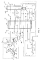
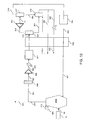
- Fluid 24 consisting of fumes is compressed in a compressor 101, in particular to compensate for losses in the various equipment of the installation. Note that this compression can also be combined with the so-called draw compression of the boiler giving rise to smoke. It can also be carried out between other stages of the process, or downstream of the CO 2 separation process;
- the compressed fluid 30 is injected into a filter 103 to remove the particles to a concentration level of less than 1 mg / m 3 , preferably less than 100 ⁇ g / m 3 .
- the de-dusted fluid 32 is cooled to a temperature close to 0 ° C, generally between 0 ° C and 10 ° C, so as to condense the water vapor that it contains.
- This cooling is performed in a tower 105, with two-level water injection, cold water 36 and water at a temperature close to the humid temperature of the ambient air 34. It is also possible to envisage indirect contact. Tower 105 may or may not have packings.
- the dried fluid 40 is then introduced into the exchanger 109 where the fluid is cooled to a close temperature, but in any case, greater than the solidification temperature of the CO 2 .
- This can be determined by those skilled in the art knowing the pressure and the composition of the fluid 40 to be treated. The latter is located around -100 ° C if the CO 2 content of the fluid to be treated is of the order of 15% by volume and for a pressure close to atmospheric pressure.
- the fluid 46 is then heated in the exchanger 109.
- the fluid 48 may also serve in particular to regenerate the residual vapor removal unit 107 and / or to produce the cold water 36a by evaporation in a tower with direct contact 115 where a dry fluid 50 is introduced which will saturate with water by vaporizing a part.
- the cold water may be further cooled in a refrigeration unit 119.
- the solid 62 comprising mainly CO 2 is transferred to a bath of liquid CO 2 121.
- Liquid 64 comprising mainly CO 2 is taken from bath 121. This liquid is divided into three streams. In the example, the first is obtained by an expansion 65 to 5.5 bar absolute producing a two-phase fluid, gas-liquid, 66. The second, 68, is obtained by compression 67, for example at 10 bar. The third, 70, is compressed for example at 55 bar. The 5.5 bar level brings cold to a temperature close to that of the triple point of CO 2 . The level at 10 bar allows the transfer of the latent heat of vaporization of the fluid 68 to about -40 ° C. Finally, at 55 bar, the fluid 70 does not vaporize during the exchange 109. This allows a good valuation of the frigories contained in the fluid 64 during the exchange 109 while limiting the energy required to produce a flow of CO 2 purified and compressed 5.
- a refrigerating cycle 200 employing a working fluid 51 which is argon. It comprises successively: a compression 129, possibly two compressions 56 and 57, a cooling by indirect exchange 109, a quasi isentropic expansion 131 which induces a cooling, a warming in the enclosure 111, a warming 109.
- a part of the working fluid is removed, then undergoes a near-isentropic expansion 130, then an indirect exchange 109 and finally a compression 128 to join the compression 129.
- the almost isentropic detents 130 and 131 provide a work from which a part serves for the compressions 56 and 57.
- This cycle 200 produces cold between about -100 and -120 ° C for the cryo-condensation 111 and between about 5 ° C and -100 ° C to overcome the cold deficit during the exchange 109.
- Another part of the cold required for the first cooling 109 is provided by an additional refrigerant cycle 181, 183, for example of the inverted Rankine type.
- Another part of the cold necessary for the second cooling 111 is provided by an additional refrigerant cycle 191, 193 for example of the inverted Rankine type.
- the CO 2 -rich primary fluids 66, 68, 70 are stagedly compressed 141, 142, 143.
- the first stages compress gas streams.
- the compressed CO 2 75 is cooled by an indirect contact exchanger to be liquid. Then it is mixed with the stream 73. This liquid mixture is pumped to the transport pressure (fluid 5).
- the transport pressure is generally supercritical, supercritical fluids will be considered to be supercritical fluids at a temperature below that of the CO 2 critical point.
- the figure 2 illustrates a variant of the quasi isentropic expansion with production of work, where the working fluid is the gas low in CO 2 44.
- the cryo-condensation process is the same as on the figure 1 . Only the changes are detailed below.
- the low-CO 2 gas 44 is compressed for example by a stepped compressor 315.
- the fluid 303 is cooled, if necessary, to the inlet temperature of the exchanger 109 via the exchanger 316. It can be in direct contact or indirect.
- the compressed CO 2 -reduced gas 304 is cooled in the exchanger 109 to be able to be expanded in the turbine 312 (virtually isentropic expansion), in order to supply a part of the cold necessary for the exchange 111.
- the fluid 307 leaving the Exchanger 111 is again expanded (almost isentropic expansion) to provide work and cold for the exchanger 111 via the fluid 308.
- This expansion loop CO 2 -lean gas can be repeated as many times as necessary.
- the low-CO 2 gas 46 is heated in the exchanger 109.
- the outgoing fluid 48 is treated as the fluid 48 of the figure 1 .
- Part of the cold necessary for the exchanger 111 can be provided by a Rankine-type refrigerant cycle 191, 193.
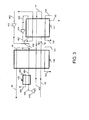
- the figure 3 illustrates another variant of quasi-isentropic relaxation with work output.
- the low-CO 2 gas 44 yields these frigories in the exchangers 111 and 109. It is then compressed by the stage compressor 415. Then it is cooled if necessary to the inlet temperature of the exchanger 109 in the exchanger 416. This may be direct or indirect contact.
- the gas low in CO 2 404 is again cooled in the exchanger 109 before being expanded by the turbine 412.
- This quasi isentropic turbine produces the cold necessary to offset part of the deficiency of frigories of the exchanger 111.
- the fluid 407 is again expanded by the quasi-isentropic turbine 414.
- the fluid 408 gives up its frigories to compensate for a part of the deficit of frigories of the exchanger 111.
- This loops loop of the CO 2 -lean gas can be repeated as much many times as necessary.
- the low-CO 2 gas 46 is heated in the exchanger 109. Finally, the outgoing fluid 48 is treated as the fluid 48 of the figure 1 .
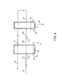
- the figure 4 illustrates another variant of quasi-isentropic relaxation with work output.
- the fluid to be treated 40 is compressed by the compressor 512 which can be stepped.
- the CO 2 -lean gas is expanded in a near isentropic turbine 514.
- the temperature of the fluid 503 must remain above the cryo-condensation temperature of the CO 2 .
- the solid CO 2 62 is poured into the liquid bath 121 and the following steps are the same as those described in FIG. figure 1 (from bath 121 and stream 64).
- the CO 2 poor gas 44 transmits its frigories to the exchangers 111 and 109.
- the outgoing fluid 48 is treated as the fluid 48 of the figure 1 .
- the figure 5 illustrates another variant of the quasi-isentropic relaxation with production of work, in which the working fluid is the fluid to be treated.
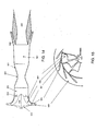
- This 612 expansion turbine must be designed with great care. It must be suitable for large flows such as those of fumes 40 of an industrial plant, have a very good isentropic efficiency, and resist the possible additional erosion due to the presence of solid CO 2 . To do this, it allows the presence of dry ice in the rotor part of the turbine (zone between the leading edge 951 and the trailing edge 954 on the Figures 14 and 15 and prohibit or minimize it in the stator part 960 upstream of the rotor part (zone lying upstream of the trailing edge of the stator vanes 950) so as not to erode the edge of the rotor. etching attack 952 of the rotor part.
- the CO 2 is in the vapor or supersaturated vapor state in the stator part, or that it has carbon dioxide nuclei sufficiently small to prevent erosion of the rotor part (lower at 10 ⁇ m, preferably 1 ⁇ m of hydraulic diameter).
- the turbine may be radial (centripetal or centrifugal). It can be supersonic shock wave. It can be axial.
- This last technology is best suited to large flows, but it requires many successive stator and rotor stages. To avoid erosion, it will be preferable to separate the dry ice downstream of each rotor stage, before the entry of the fluid into the next stator stage.
- the first two technologies have the advantage of remaining effective for high relaxation rates (greater than 10), so they avoid having to perform multiple separations.
- This carbon dioxide is then separated from the CO 2 depleted gas in a separator 612 so as to obtain a solid comprising mainly CO 2 62 and a gas that is poor in CO 2 44.
- This separation can be done downstream of the rotor part by using the rotation of the fluid in the rotor part and the centrifugal effect to separate a CO 2 -rich fraction at the periphery of a CO 2 fraction in the center. It may also be interesting to realize a setting speed and thus additional relaxation of the fluid in a convergent 956 (so-called Laval turbine). By decreasing the pressure before deceleration of the gas, this makes it possible to increase the amount of solidified CO 2 . Most of the CO 2 -lower gas is recovered at the center of the 959 flow and most of the solid CO 2 at the periphery 958 is mixed with a gas fraction.
- an additional refrigerant cycle 191, 193 of the Rankine type or comprising a quasi isentropic expansion of a working fluid with or without production of work brings cold to the separator 612.
- the solid comprising predominantly CO 2 62 is poured into the liquid bath 121 and the following steps are the same as those shown in FIG. figure 1 .
- the CO 2 -rich gas is heated by heat exchange with the fluid to be treated in the exchanger 109.
- the fluid 605 is then compressed at a pressure greater than or equal to atmospheric pressure.
- the outgoing fluid 48 is treated as in the figure 1 .
- the figure 6 illustrates an embodiment with almost isentropic relaxation without production of work.
- the fluid to be treated 42 is still cooled below the cryo-condensation temperature of CO 2 in enclosure 111 to produce a gas 701 low in CO 2 and cooled. It is also possible to place this chamber after the "relaxation / Venturi" portion 702 of the process, which will now be described.
- Part of the CO 2 to be captured has solidified in the form of a solid containing mainly CO 2 62 and is extracted from the enclosure 111.
- the fluid 701 is rotated around it. an axis substantially parallel to the direction of its flow by a system of fixed vanes 717.
- the fluid 703 is expanded at the outlet of the fins and cools below the cryo-condensation temperature of CO 2 without producing work.
- the expansion can be effected by the Venturi effect by passing the fluid in a restriction 718. Solid particles comprising predominantly CO 2 are formed and are recovered at the periphery of the flow due to the centrifugal effect induced by the rotation fluid.
- a 705 mixture of solid is recovered, mainly comprising CO 2 and gas.
- the incondensables 44, 46 outgoing yield their frigories in the exchangers 111 and 109.
- the stream 705 is composed mainly of solid, however it may be necessary to separate the residual gas from the solid in a separator pot 731.
- the incondensable part then yields its frigories in the exchangers 111 and 109.
- the solid comprising predominantly CO 2 62 is poured into the liquid bath 121 and undergoes the same steps as those described in FIG. figure 1 .
- Fluxes 48 are used to cool the water, in the same way as the flow 50 of the figure 1 .
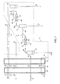
- the figure 7 illustrates another embodiment with almost isentropic relaxation without production of work.
- the fluid to be treated 40 is under pressure, for example up to 60 bar (compression performed by the compressor 101 or by an additional compressor). It is possibly more concentrated in CO 2 than in the other examples, typically between 50 and 90% by volume.
- the exchange 809 has the same characteristics as the exchange 109 of the figure 1 .
- the exchanger 811 cools the fluid to be treated 42 at a temperature below the liquefaction temperature of the CO 2 . There comes out a cooled 801 process fluid that is sent to a separator pot 812.
- a liquid rich in CO 2 816 is extracted by the separator 812.
- the residual fluid 802 is rotated about an axis substantially parallel to the flow direction by a fixed fin system 817. It is expanded at the outlet 803 of the fins after it is rotated and cools below the cryo-condensation temperature of CO 2 without producing work.
- the expansion can be effected by Venturi effect by passing the fluid in a restriction 818.
- Solid particles comprising predominantly CO 2 are formed and are recovered at the periphery of the flow due to the centrifugal effect induced by the rotation of the fluid.
- the stream 805 is composed mainly of solid, however it may be necessary to separate the residual gas from the solid in a separator pot 841.
- the incondensables 44 yield their frigories in the exchangers 811 and 809.
- the solid 62 comprising mainly CO 2 recovered at the outlet of separator pots 841 and optionally 851 is poured into the liquid bath 121 and treated as in figure 1 . Fluxes 48 are used to cool the water, in the same way as the flow 50 of the figure 1 .
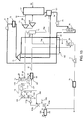
- the figure 8 represents a coal-based electricity generation plant, using different purification units 4, 5, 6 and 7 of the fumes 19.
- a primary air flow 15 passes through the unit 3 where the coal 15 is sprayed and driven to the burners of the boiler 1.
- a secondary air flow 16 is supplied directly to the burners to provide additional oxygen. necessary for an almost complete combustion of coal.
- Supply water 17 is sent to boiler 1 to produce steam 18 which is expanded in a turbine 8.
- the fumes 19 from combustion comprising nitrogen, CO 2 , water vapor and other impurities, undergo several treatments to remove some of said impurities.
- Unit 4 removes NOx for example by catalysis in the presence of ammonia.
- Unit 5 removes dust for example by electrostatic filter and unit 6 is a desulfurization system for removing SO2 2 and / or SO 3 .
- Units 4 and 6 may be redundant depending on the composition of the required product.
- the purified flow 24 from unit 6 (or 5 if 6 is not present) is sent to a low temperature purification unit 7 by cryo-condensation to produce a relatively pure CO 2 flow rate 26 and a waste flow rate. 25 enriched in nitrogen.
- This unit 7 is also called CO 2 capture unit and implements the method object of the invention, as illustrated, for example, by the Figures 1 to 7 .
- the figure 9 represents a coal-based power generation installation, implementing different purification units 5 and 7 of the fumes 19.
- a primary air flow 15 passes through unit 3, where coal 15 is pulverized and driven to the burners of boiler 1.
- a secondary oxidizer flow 16 is supplied directly to the burners to provide additional oxygen. necessary for an almost complete combustion of coal. This secondary oxidant results from the mixture of recirculated fumes 94 using a fan 91 and oxygen 90 produced by an air separation unit 10.
- Supply water 17 is sent to the boiler 1 to produce steam 18, which is expanded in a turbine 8.
- Unit 5 removes dust, for example by means of an electrostatic filter.
- the de-dusted flow 24 from the unit 5 is sent to a low temperature purification unit 7, by cryo-condensation, to produce a relatively pure CO 2 flow rate 26 and a nitrogen-enriched residual flow rate.
- This unit 7 is also called CO 2 capture unit and implements the method object of the invention, as illustrated, for example, by the Figures 1 to 7 .
- the fluid 93 may be in liquid, gaseous or two-phase form and consists of a mixture of cooled air gases.
- it may be air or cold nitrogen gas (between -56 ° C and -196 ° C), or air or liquid nitrogen. It is intended to be introduced in the enclosure referenced 111 on the Figures 1 to 4 and on the figure 6 , 612 on the figure 5 , 731 on the figure 6 and finally 841, 851 on the figure 7 .
- the unit 7 can also produce a fluid 92 that will be used in the air separation unit.
- a fluid 92 that will be used in the air separation unit.
- it may be a fraction of the lean gas leaving the enclosure 111 of the Figures 1 to 4 and 6 , 612 of the figure 5 , 731 of the figure 7 and 841, 851 of the figure 8 .
- This lean gas in a way, returns cold to the unit 10 at a higher temperature level than that brought from the unit 10 by the fluid 93. It is advantageous to vary the flow rate of this fluid injection 93 over time. For example, it is possible to produce and store liquid nitrogen at night, when the energy is available and inexpensive, and to inject the liquid nitrogen during the day. in order to reduce the energy consumed.
- the moment when the cold is produced by the unit 10 for example liquid nitrogen
- the unit 7 is dissociated. In this case, the quasi-isentropic expansion of a gas can be carried out in the unit 10 rather than unit 7.
- This scheme may prove to be well adapted to cases of modification of existing factories, where the replacement of the primary air sent to the carbon sprays by a mixture of recycled fumes plus oxygen can prove to be complex, partly because of the increasing the water content, fumes containing much more than moist air, and secondly for safety reasons, although this should not be overestimated.
- the figure 10 schematically represents the use of a process according to the invention in a steel plant.
- An air separation unit 10 provided with oxygen 90 to a blast furnace 900 in which iron ore 901 and carbon products 902 (coal and coke) are also introduced.
- the blast furnace works in this case in the presence of very little nitrogen.
- the blast furnace gases 903 composed for example of 47% of CO, 36% of CO 2 , 8% of N 2 and 9% of other compounds such as H 2 and H 2 O can be divided in two. Most of the 905 goes to the CO 2 capture unit, another part 904 serves to deconcentrate the nitrogen content in the loop.
- the fluid 905 is previously cooled in a direct contact heat exchanger 906, dedusted in the filter 103, then compressed by a compressor 901, cooled in a heat exchanger 105 and dried in a dryer 107, before entering the heat exchanger at low temperature 109, where it will be cooled and then partially liquefied at a temperature close to the triple point of CO 2 without formation of solid.
- the two-phase gas-liquid fluid 912 obtained is separated into a gaseous fraction 502 and a liquid fraction 920 in the separator 928.
- the gaseous fraction 502 is then cooled by a quasi-isentropic expansion, for example in a turbine 514, so as to obtain a two-phase gas-solid fluid 503.
- This is separated in the chamber 111 into a gas fraction 44 and a solid fraction 62 rich in CO 2 .
- the solid fraction 62 is compressed for example by a worm and mixed with the liquid 920 in the bath 121, which is heated by gas 72 produced by the vaporization of the liquid 74 in the exchanger 109.
- the liquid CO 2 64 is compressed by a pump 69 so as to obtain a pressurized liquid 70 and heated in the exchanger 109 without undergoing vaporization, or pseudo-vaporization if the pressure is greater than the supercritical pressure.
- the lean gas is successively heated by a compressor 315 and the exchanger 109.
- the invention can also be adapted for types of blast furnace operating with enriched air, for example by adding a CO / N 2 separation by cryogenic distillation, cooling the gas 44 to the necessary temperature.
- the figure 11 schematically represents the use of a process according to the invention in an installation for producing synthesis gas from an oxygen process (partial oxidation, gasification, auto-thermal reformer, etc.).
- An air gas separation unit 10 supplies oxygen 90 to a reactor 900 into which a carbon product 902 (coal, natural gas, biomass, household waste, etc.) is introduced.
- the synthesis gas 903 mainly comprises the compounds CO, CO 2 , H 2 and H 2 O.
- the CO can be converted (so-called shift reaction) into CO 2 and H 2 in the presence of water vapor: CO + H 2 O ⁇ -> CO 2 + H 2 in unit 907.
- This unit may also include one or more exchangers for cooling the gas before compression.
- the fluid 905 may optionally be dedusted in a filter 103, then compressed by a compressor 101, cooled in an exchanger 105 and dried in a dryer 107, before entering the low temperature heat exchanger 109, where it may be partially liquefied at a temperature close to that of the triple point of CO 2 .
- This two-phase gas-liquid fluid 912 is separated into a gas fraction 502 and a liquid fraction 920 into the separator 928.
- the gaseous fraction 502 is then cooled by a quasi-isentropic expansion, for example in a turbine 514, so as to obtain a gas-solid two-phase flow 503.
- This is separated into a gaseous fraction 44 and a fraction a solid rich in CO 2 62 in the enclosure 111.
- the solid fraction 62 is mixed with the liquid 920 in the bath 121, which is heated by gas 74 produced by the vaporization of the liquid 72 in the exchanger 109.
- the liquid CO 2 64 is compressed by a pump and heated in the exchanger 109 without undergoing vaporization, or pseudo-vaporization if the pressure is greater than the supercritical pressure.
- the lean gas 44 is successively heated by a compressor 924 and the exchanger 109.
- This lean gas consists essentially of hydrogen can be sent to a gas turbine to achieve combustion without CO 2 emission.
- the unit 10 can supply hot nitrogen 90a, which will be introduced downstream of the dryers 910, and / or cold nitrogen 90b, introduced directly into the chamber 111 to increase the amount of CO 2 captured.
- the expansion in the turbine 514 of the hot nitrogen present in the flow 502 provides additional cooling for the solid cryo-condensation of CO 2 in the turbine 514; in the second case, the cold nitrogen 90b, by heating in contact with the fluid 503, generates the solid cryo-condensation of CO 2 .
- the other advantage of the hot nitrogen 90a is to increase the molecular weight of the gas 502, which may be advantageous for reducing the cost of the expansion 514 and / or the compression 924. Indeed, when these gases are very rich in hydrogen, it is not easy to compress / relax these gases with the most suitable technologies for large flows namely axial type technologies, radial or supersonic shock wave. It is then necessary to use volumetric type technologies such as piston or screw very expensive to implement.
- the figure 12 schematically represents the use of a process according to the invention in a synthesis gas production facility from a steam reforming.
- Carbonaceous product 902 (natural gas, methanol, naphtha, etc.) is introduced into a reactor 900.
- the synthesis gas 903 produced in the reactor 900 mainly comprises the compounds CO, CO 2 , H 2 and H 2 O.
- the fluid 905 may optionally be compressed by a compressor 101, cooled in an exchanger 105 and dried in a dryer 107, before entering a low temperature exchanger 109, where it can be partially liquefied at a temperature close to that of the triple point of CO 2 .
- the two-phase gas-liquid fluid 912 obtained is separated into a gaseous fraction 502 and a liquid fraction 920 in the separator 928.
- the gaseous fraction 502 is then cooled by a quasi-isentropic expansion, for example in a turbine 514, so as to obtain a gas-solid biphasic 503.
- the solid fraction 62 is mixed with the liquid 920 in the bath 121, which is heated by gas 74 produced by the vaporization of the liquid 72 in the exchanger 109.
- the liquid CO 2 64 is compressed by a pump and heated in the exchanger 109 without undergoing vaporization, or pseudo-vaporization if the pressure is greater than the supercritical pressure.
- the lean gas 44 can then be purified to CO 2 at low temperature, for example by adsorption with a 13X molecular sieve before being introduced into a cryogenic unit 924 for the production of CO. This works for example by washing with methane or partial condensation of CO.
- This unit 924 produces a hydrogen enriched gas 929 and a CO 925 enriched gas.
- One or more fluids of this unit can be compressed at low temperature and then reintroduced into the heat exchanger 926.
- the solid cryo-condensation replaces an elimination of CO 2 by absorption with amines (MDEA or MEA). If it is desired to produce pure hydrogen, it is possible to add a PSA H 2 in this scheme either upstream of this purification by solid cryo-condensation that is to say at the outlet of reformer 900 after cooling synthesis gas, either on the gas rich in H 2 929.
- the figure 13 schematically represents a variant of the invention associated with a method implementing a transcritical Rankine cycle on CO 2 . It also includes the characteristics of a process where a liquid cryo-condensation is successively carried out, then a solid cryo-condensation and where the purity of the CO 2 produced by two distillation columns, one to eliminate the components, is improved. less volatile than CO 2 (NO 2 or N 2 O 4 , SO 2 , ...) and another to remove more volatile components.
- the fluid 24 consists of fumes and may be at a temperature of the order of 150 ° C is injected into a filter 103 to remove the particles to a concentration level of less than 1 mg / m 3 , preferably less than 1 mg / m 3. 100 ⁇ g / m 3 .
- the dust-free fluid 30 is cooled to a temperature close to 0 ° C., generally between 0 ° C. and 10 ° C., so as to condense the water vapor that it contains.
- This cooling is performed in a tower 105b, with two-level water injection, cold water 36b and water at a temperature close to the humid temperature of the ambient air 34b.
- Tower 105 may or may not have packings. This tower can also serve as an SO 2 scrubber.
- the optionally desaturated fluid is compressed at a pressure between 5 and 50 bar abs in the compressor 101.
- the fluid 32 is cooled to a temperature close to 0 ° C., generally between 0 ° C. and 10 ° C. C, so as to condense the water vapor that it contains.
- This cooling is performed in a tower 105, with two-level water injection, cold water 36 and water at a temperature close to the humid temperature of the ambient air 34. It is also possible to envisage indirect contact.
- Tower 105 may or may not have packings.
- the fluid to be treated 40 is cooled, then contacted in a distillation column 79 with pure CO 2 , so as to recover the less volatile compounds that the CO 2 in the form of a liquid containing CO 2 and for example NO 2 (or its dimer N 2 O 4 ).
- This liquid can be pumped and vaporized in the unit 78, and then sent, either into a combustion chamber to reduce the NO 2 , or into the purification unit of the stream 30 by low pressure SO 2 washing, to serve it.
- reagent either directly as NO 2 , or as nitric acid after reaction with water.
- the fluid to be treated 74a is then cooled and partially condensed in liquid form and sent to the separator 76.
- the liquid fraction 76a is sent to the bath 121.
- the gaseous fraction 76b is sent to an expansion turbine so as to produce a two-phase flow therein.
- gas-solid 42 which is sent into the chamber 111 to be separated there between a gas low in CO 2 44 and solid CO 2 62.
- An auxiliary fluid 93 for example from a gas separation unit of the air can possibly provide additional cooling for solid cryo-condensation. In this case, it may be advantageous to take from the CO 2 gas 44 a fluid 92 which returns to the unit which supplied the fluid 93.
- the solid 62 is compressed for example by an endless screw and injected into the liquid CO 2 bath 121, wherein a liquid is taken 64.
- This liquid can optionally be pumped and introduced into a distillation column 80 to remove more volatile compounds that CO 2 .
- the pure liquid 68 is heated without undergoing vaporization, or pseudo-vaporization if it is supercritical. It can be pumped again to obtain the fluid ready for transport.
- Part of the fluid can be removed for vaporization, or pseudo-vaporization, in a unit 72.
- This unit 72 is for example any source of heat from the plant producing the fluid to be treated.
- This portion of the fluid is then expanded in a turbine 73 serving to produce electricity or mechanical power, then cooled in the exchanger 109 and condensed by direct exchange in the bath 121, while carrying out the melting of the solid CO 2 .
- the fluid 48 may also serve in particular to regenerate the residual vapor removal unit 107 and / or to produce the cold water 36a by evaporation in a tower with direct contact 115 where a dry fluid 50 is introduced which will saturate with water by vaporizing a part.
- the cold water can undergo additional cooling in a refrigeration unit 119. Then, this cold water can be used in one and / or the other of the towers 105 and 105b so as to cool the gas to be treated before and / or after compression.
- the Figures 14 and 15 represent a turbine for practically isentropic expansion of the fluid to be treated with production of external work according to the invention.
- the upstream stator portion 960 begins with the volute (not shown) and then with vanes 950 which can be fixed or variable. Then returns to the rotor portion 960 which comprises for example fins 952 with a leading edge 951 where begins the rotor portion 960 and a trailing edge 954 where it ends.
- the rotor part Downstream of the rotor part, if it is not desired to use the centrifugal force on the solid parts, the rotor part may consist of a simple deceleration cone.
- downstream stator portion 961 it is possible to use the rotation of the fluid in the rotor part as well as the centrifugal effect to separate a fraction rich in CO 2 at the periphery of a fraction CO 2 depleted in the center. It may also be interesting to realize a speed setting and therefore an additional relaxation of the fluid in a convergent 956 (turbine called "Laval"). By decreasing the pressure before deceleration of the gas, this makes it possible to increase the amount of solidified CO 2 . Most of the CO 2 -lower gas is recovered at the center of the 959 flow and most of the solid CO 2 at the periphery 958 is mixed with a gas fraction.
Landscapes
- Engineering & Computer Science (AREA)
- Physics & Mathematics (AREA)
- Mechanical Engineering (AREA)
- Thermal Sciences (AREA)
- General Engineering & Computer Science (AREA)
- Chemical & Material Sciences (AREA)
- Chemical Kinetics & Catalysis (AREA)
- Oil, Petroleum & Natural Gas (AREA)
- General Chemical & Material Sciences (AREA)
- Manufacturing & Machinery (AREA)
- Combustion & Propulsion (AREA)
- Analytical Chemistry (AREA)
- Organic Chemistry (AREA)
- Separation By Low-Temperature Treatments (AREA)
- Carbon And Carbon Compounds (AREA)
- Treating Waste Gases (AREA)
- Organic Low-Molecular-Weight Compounds And Preparation Thereof (AREA)
Claims (7)
- Verfahren zur Herstellung von gekühltem Wasser (36a), von mindestens einem CO2-armen Gas (44) und von einem oder mehreren mit CO2 angereicherten Primärfluiden (64, 66, 68, 70) ausgehend von einem zu behandelnden Fluid (40), das von industriellen Rauchgasen gebildet ist, die CO2, mindestens eine flüchtigere Verbindung als CO2 und Industriewasser (58) enthalten, das die Trennung (109, 111) des zu behandelnden Fluids (40) in mindestens das CO2-arme Gas (44) und in mindestens ein CO2-reiches Primärfluid (64, 66, 68, 70) umfasst; und dadurch gekennzeichnet, dass es einen Schritt der Kühlung des Industriewassers (58) durch Wärmeaustausch in einem Turm mit direktem Kontakt (115) mit einer Fraktion ungleich Null des CO2-armen Gases (50) umfasst, derart, dass das gekühlte Wasser (36a) erhalten wird.
- Verfahren nach Anspruch 1, dadurch gekennzeichnet, dass es ferner einen Schritt c) aufweist, bei dem ein Wärmeaustausch (105) zwischen einer Fraktion ungleich Null des zu behandelnden Fluids (32) und einer Fraktion ungleich Null des gekühlten Wassers (36), das in Schritt b) hergestellt wurde, durchgeführt wird, derart, dass das zu behandelnde Fluid (32) vor dessen Durchführung in Schritt a) gekühlt wird.
- Verfahren nach Anspruch 2, dadurch gekennzeichnet, dass, in Schritt c), der Wärmeaustausch (105) durch direkten Kontakt erfolgt.
- Verfahren nach Anspruch 3, dadurch gekennzeichnet, dass es ferner einen Schritt c0) umfasst, bei dem das zu behandelnde Fluid (32), vor dessen Durchführung in Schritt c), gekühlt wird durch direkten Kontakt (105) mit einem Wasserstrom (34) mit einer Temperatur, die höher als die Feuchttemperatur der Umgebungsluft ist.
- Verfahren nach einem der Ansprüche 2 bis 4, dadurch gekennzeichnet, dass es ferner einen Schritt b1) umfasst, bei dem das gekühlte Wasser (36a), das in Schritt b) hergestellt wurde, vor dessen Durchführung in Schritt c) in einem Kühlanlage (119) gekühlt wird.
- Verfahren nach einem der Ansprüche 2 bis 5, dadurch gekennzeichnet, dass es ferner, nach dessen Durchführung in Schritt c) und vor dessen Durchführung in Schritt a), einen Schritt c1) der Trocknung in einer Adsorptionseinheit (107) und/oder Verdichtungseinheit (101a, 512) des zu behandelnden Fluids (38) umfasst.
- Verfahren nach einem der Ansprüche 1 bis 6, dadurch gekennzeichnet, dass Schritt a) aus den folgenden Teilschritten besteht:a1) eine erste Kühlung (109) des zu behandelnden Fluids (40) durch Wärmeaustausch ohne Zustandsänderung;a2) eine zweite Kühlung (111) mindestens eines Teils des zu behandelnden Fluids (42), die in Schritt a) gekühlt wurden, derart, dass mindestens ein Festkörper (62) erhalten wird, der überwiegend CO2 und mindestens das CO2-arme Gas (44) enthält; unda3) einen Schritt, der die Verflüssigung und/oder die Sublimation mindestens eines Teils des Festkörpers (62) umfasst und es ermöglicht, das eine oder die mehreren CO2-reichen Primärfluide (66, 68, 70) zu erhalten.
Applications Claiming Priority (2)
| Application Number | Priority Date | Filing Date | Title |
|---|---|---|---|
| FR0858866A FR2940413B1 (fr) | 2008-12-19 | 2008-12-19 | Procede de capture du co2 par cryo-condensation |
| PCT/FR2009/052509 WO2010076467A1 (fr) | 2008-12-19 | 2009-12-14 | Procédé de capture du co2 et de production d'eau froide |
Publications (2)
| Publication Number | Publication Date |
|---|---|
| EP2379971A1 EP2379971A1 (de) | 2011-10-26 |
| EP2379971B1 true EP2379971B1 (de) | 2014-02-12 |
Family
ID=40943851
Family Applications (3)
| Application Number | Title | Priority Date | Filing Date |
|---|---|---|---|
| EP09803854A Withdrawn EP2379199A1 (de) | 2008-12-19 | 2009-12-14 | Verfahren zum einfangen von co2 durch feststoffcryokondensation in einer turbine |
| EP09803851.6A Not-in-force EP2379971B1 (de) | 2008-12-19 | 2009-12-14 | Co2-gewinnungs- und kaltwassererzeugungsverfahren |
| EP09803850A Withdrawn EP2379970A1 (de) | 2008-12-19 | 2009-12-14 | Verfahren zur co2-rückgewinnung mittels kryokondensation |
Family Applications Before (1)
| Application Number | Title | Priority Date | Filing Date |
|---|---|---|---|
| EP09803854A Withdrawn EP2379199A1 (de) | 2008-12-19 | 2009-12-14 | Verfahren zum einfangen von co2 durch feststoffcryokondensation in einer turbine |
Family Applications After (1)
| Application Number | Title | Priority Date | Filing Date |
|---|---|---|---|
| EP09803850A Withdrawn EP2379970A1 (de) | 2008-12-19 | 2009-12-14 | Verfahren zur co2-rückgewinnung mittels kryokondensation |
Country Status (5)
| Country | Link |
|---|---|
| US (3) | US20110302955A1 (de) |
| EP (3) | EP2379199A1 (de) |
| CN (3) | CN102317207A (de) |
| FR (1) | FR2940413B1 (de) |
| WO (3) | WO2010076466A1 (de) |
Families Citing this family (44)
| Publication number | Priority date | Publication date | Assignee | Title |
|---|---|---|---|---|
| EP2290202A1 (de) * | 2009-07-13 | 2011-03-02 | Siemens Aktiengesellschaft | Heizkraftwerk und Heizkraftverfahren |
| CN102740941A (zh) * | 2010-02-03 | 2012-10-17 | 埃克森美孚上游研究公司 | 使用冷却液从工艺气流中去除可凝固的气体组分的系统和方法 |
| US20120023947A1 (en) * | 2010-07-30 | 2012-02-02 | General Electric Company | Systems and methods for co2 capture |
| FR2972793A1 (fr) * | 2011-03-16 | 2012-09-21 | Air Liquide | Procede et appareil de liquefaction d'un gaz riche en co2 contenant au moins une impurete legere |
| EP2505948B1 (de) * | 2011-03-30 | 2018-10-10 | General Electric Technology GmbH | Kryogene CO2-Trennung mithilfe eines Kühlsystems |
| EP2866921B1 (de) * | 2011-05-26 | 2026-04-22 | Sustainable Energy Solutions, LLC | System zur trennung von kondensierbaren dämpfen von leichten gasen oder flüssigkeiten durch rekuperative kryogene verfahren |
| FR2976059B1 (fr) * | 2011-05-31 | 2013-05-31 | Air Liquide | Appareil et procede integre de separation d'un melange de dioxyde de carbone et au moins un autre gaz et de separation d'air par distillation cryogenique |
| US20130025317A1 (en) * | 2011-06-15 | 2013-01-31 | L'Air Liguide Societe Anonyme Pour L' Etude Et L' Exploitation Des Procedes Georges Claude | Process for Removing Carbon Dioxide From a Gas Stream using Desublimation |
| US20130025294A1 (en) * | 2011-07-28 | 2013-01-31 | Christian Vogel | System and method for carbon dioxide removal |
| US20130084794A1 (en) * | 2011-09-29 | 2013-04-04 | Vitali Victor Lissianski | Systems and methods for providing utilities and carbon dioxide |
| US20130111948A1 (en) * | 2011-11-04 | 2013-05-09 | Air Products And Chemicals, Inc. | Purification of Carbon Dioxide |
| US20130125580A1 (en) * | 2011-11-22 | 2013-05-23 | General Electric Company | Expander and method for co2 separation |
| US20130239608A1 (en) * | 2011-11-22 | 2013-09-19 | General Electric Company | System and method for separating components in a gas stream |
| FR2988167B1 (fr) * | 2012-03-13 | 2018-06-15 | L'air Liquide, Societe Anonyme Pour L'etude Et L'exploitation Des Procedes Georges Claude | Procede et appareil de separation d'un melange contenant du dioxyde de carbone par distillation |
| FR2988166B1 (fr) | 2012-03-13 | 2014-04-11 | Air Liquide | Procede et appareil de condensation d'un debit gazeux riche en dioxyde de carbone |
| CN102606240A (zh) * | 2012-03-27 | 2012-07-25 | 中国科学院微电子研究所 | 一种利用co2发电的系统及方法 |
| US20130283852A1 (en) * | 2012-04-26 | 2013-10-31 | General Electric Company | Method and systems for co2 separation |
| FR2992056B1 (fr) * | 2012-06-15 | 2018-11-09 | L'air Liquide,Societe Anonyme Pour L'etude Et L'exploitation Des Procedes Georges Claude | Procede et appareil de refroidissement ou de rechauffage d'un melange gazeux |
| FR2993353B1 (fr) * | 2012-07-13 | 2018-06-15 | Air Liquide | Procede et appareil de purification d'un melange riche en dioxyde de carbone a basse temperature |
| US20140144178A1 (en) * | 2012-11-28 | 2014-05-29 | L'Air Liquide Societe Anonyme Pour L'Etude Et L'Expoitation Des Procedes Georges Claude | Optimized heat exchange in a co2 de-sublimation process |
| CN103344090B (zh) * | 2013-06-19 | 2016-06-22 | 曲昭波 | 液化空气制冷和灭火系统 |
| US20150033792A1 (en) * | 2013-07-31 | 2015-02-05 | General Electric Company | System and integrated process for liquid natural gas production |
| EP2873939B1 (de) * | 2013-11-19 | 2019-02-27 | L'air Liquide, Societe Anonyme Pour L'etude Et L'exploitation Des Procedes Georges Claude | Verfahren und Vorrichtung zur Herstellung von CO und CO2 |
| US10473029B2 (en) * | 2013-12-30 | 2019-11-12 | William M. Conlon | Liquid air power and storage |
| NL2013653B1 (en) * | 2014-10-20 | 2016-10-04 | Haffmans Bv | A process installation for preparing a carbon dioxide (CO2) end product from a gaseous carbon dioxide containing starting product. |
| WO2016195999A1 (en) * | 2015-06-03 | 2016-12-08 | Conlon William M | Liquid air power and storage with carbon capture |
| EP3554675A4 (de) * | 2016-12-13 | 2020-07-08 | Linde GmbH | Reinigungsverfahren zur herstellung von hochreinem kohlenmonoxid |
| US20180187972A1 (en) * | 2017-01-05 | 2018-07-05 | Larry Baxter | Device for Separating Solid Carbon Dioxide from a Suspension |
| JP6776154B2 (ja) * | 2017-02-27 | 2020-10-28 | 三菱重工マリンマシナリ株式会社 | ラジアルタービン、ラジアルタービンの排気部材 |
| SG11202000720TA (en) * | 2017-08-24 | 2020-03-30 | Exxonmobil Upstream Res Co | Method and system for lng production using standardized multi-shaft gas turbines, compressors and refrigerant systems |
| EP3914848B1 (de) * | 2019-01-25 | 2024-10-23 | Saudi Arabian Oil Company | Verfahren und vorrichtung zum transport von flüssigem kohlenwasserstoff und co2 zur erzeugung von wasserstoff mit co2-aufnahme |
| US11486638B2 (en) | 2019-03-29 | 2022-11-01 | Carbon Capture America, Inc. | CO2 separation and liquefaction system and method |
| FR3099818B1 (fr) * | 2019-08-05 | 2022-11-04 | Air Liquide | Dispositif de réfrigération et installation et procédé de refroidissement et/ou de liquéfaction |
| CN113701446A (zh) * | 2021-04-07 | 2021-11-26 | 中国科学院理化技术研究所 | 超音速两相膨胀制冷循环的天然气液化系统 |
| CN113701449B (zh) * | 2021-07-05 | 2022-12-16 | 中国科学院理化技术研究所 | 基于氦制冷的超音速旋流两相膨胀氢液化系统及装置 |
| CN113701450A (zh) * | 2021-07-05 | 2021-11-26 | 中国科学院理化技术研究所 | 氢超音速两相直接膨胀液化系统及氢液化装置 |
| CN113701447A (zh) * | 2021-07-05 | 2021-11-26 | 中国科学院理化技术研究所 | 氢液化循环系统及氢液化装置 |
| CN113701448A (zh) * | 2021-07-05 | 2021-11-26 | 中国科学院理化技术研究所 | 基于多级超音速两相膨胀机的氢液化系统及氢液化装置 |
| CN114294039B (zh) * | 2021-12-14 | 2023-12-22 | 天地科技股份有限公司 | 一种煤矿风井中无功耗二氧化碳多路回收装置 |
| CN115382339B (zh) * | 2022-07-26 | 2024-05-07 | 中国石油大学(华东) | 用于工业制氢的超音速碳捕集能量回收装置及系统 |
| NL2034264B1 (en) * | 2023-03-03 | 2024-09-09 | Univ Delft Tech | Carbon dioxide capturing device |
| EP4491258A1 (de) * | 2023-07-14 | 2025-01-15 | Linde GmbH | Verfahren und anlage zur kühlung eines prozessgases |
| US20250198698A1 (en) * | 2023-12-19 | 2025-06-19 | Southwest Research Institute | Cryogenic-Based Carbon Dioxide Capture System |
| WO2025212518A1 (en) * | 2024-04-01 | 2025-10-09 | Carbon Capture America, Inc | Methods, systems and apparatus for processing gaseous streams including carbon dioxide |
Family Cites Families (24)
| Publication number | Priority date | Publication date | Assignee | Title |
|---|---|---|---|---|
| GB771405A (en) * | 1954-06-01 | 1957-04-03 | Union Carbide & Carbon Corp | Improvements in the cold separation of air |
| US3614872A (en) * | 1967-12-22 | 1971-10-26 | Texaco Inc | Synthesis gas separation process |
| US4791784A (en) * | 1985-06-17 | 1988-12-20 | University Of Dayton | Internal bypass gas turbine engines with blade cooling |
| JPH0914831A (ja) * | 1995-06-27 | 1997-01-17 | Mitsubishi Heavy Ind Ltd | Co2 回収装置及び回収方法 |
| CA2294742C (en) * | 1997-07-01 | 2005-04-05 | Exxon Production Research Company | Process for separating a multi-component gas stream containing at least one freezable component |
| TW366409B (en) * | 1997-07-01 | 1999-08-11 | Exxon Production Research Co | Process for liquefying a natural gas stream containing at least one freezable component |
| AU750712B2 (en) * | 1998-10-16 | 2002-07-25 | 3S Gas Technologies Ltd. | Method and Apparatus for the Separation of Components of Gas Mixtures and Liquefaction of a Gas |
| US6082133A (en) * | 1999-02-05 | 2000-07-04 | Cryo Fuel Systems, Inc | Apparatus and method for purifying natural gas via cryogenic separation |
| JP3538338B2 (ja) * | 1999-05-21 | 2004-06-14 | 株式会社神戸製鋼所 | 酸素ガスの製造方法 |
| DE19940371A1 (de) * | 1999-08-25 | 2001-03-01 | Messer Griesheim Gmbh | Verfahren und Vorrichtung zur Gewinnung von Kohlendioxid aus Abgasen |
| FR2820052B1 (fr) * | 2001-01-30 | 2003-11-28 | Armines Ass Pour La Rech Et Le | Procede d'extraction du dioxyde de carbone par anti-sublimation en vue de son stockage |
| JP4979138B2 (ja) * | 2001-01-31 | 2012-07-18 | 株式会社前川製作所 | ドライアイス製造方法とその装置 |
| US20020189443A1 (en) * | 2001-06-19 | 2002-12-19 | Mcguire Patrick L. | Method of removing carbon dioxide or hydrogen sulfide from a gas |
| US6884507B2 (en) * | 2001-10-05 | 2005-04-26 | General Electric Company | Use of high modulus, impact resistant foams for structural components |
| FR2851936B1 (fr) * | 2003-03-04 | 2006-12-08 | Procede d'extraction du dioxyde de carbone et du dioxyde de soufre par anti-sublimation en vue de leur stockage | |
| CN1956768A (zh) * | 2004-03-02 | 2007-05-02 | 中国电力株式会社 | 处理废气的方法和系统,和分离二氧化碳的方法和装置 |
| CN1956767A (zh) * | 2004-03-02 | 2007-05-02 | 中国电力株式会社 | 脱除废气中水分和有害气体组分的方法和系统 |
| EP1781400B1 (de) * | 2004-08-06 | 2013-07-03 | ALSTOM Technology Ltd | Reinigung von verbrennungsabgas mit entfernung von co2 |
| RU2272973C1 (ru) * | 2004-09-24 | 2006-03-27 | Салават Зайнетдинович Имаев | Способ низкотемпературной сепарации газа (варианты) |
| JP2006117458A (ja) * | 2004-10-20 | 2006-05-11 | Mitsubishi Heavy Ind Ltd | ドライアイス製造システム |
| FR2880677B1 (fr) | 2005-01-07 | 2012-10-12 | Air Liquide | Procede de pretraitement de l'air avant introduction dans une unite de separation d'air par voie cryogenique et appareil correspondant |
| FR2894838B1 (fr) * | 2005-12-21 | 2008-03-14 | Gaz De France Sa | Procede et systeme de capture du dioxyde de carbone present dans des fumees |
| US7867322B2 (en) * | 2007-01-31 | 2011-01-11 | Alstom Technology Ltd | Use of SO2 from flue gas for acid wash of ammonia |
| US8038388B2 (en) * | 2007-03-05 | 2011-10-18 | United Technologies Corporation | Abradable component for a gas turbine engine |
-
2008
- 2008-12-19 FR FR0858866A patent/FR2940413B1/fr not_active Expired - Fee Related
-
2009
- 2009-12-14 EP EP09803854A patent/EP2379199A1/de not_active Withdrawn
- 2009-12-14 EP EP09803851.6A patent/EP2379971B1/de not_active Not-in-force
- 2009-12-14 WO PCT/FR2009/052508 patent/WO2010076466A1/fr not_active Ceased
- 2009-12-14 WO PCT/FR2009/052509 patent/WO2010076467A1/fr not_active Ceased
- 2009-12-14 WO PCT/FR2009/052512 patent/WO2010070226A1/fr not_active Ceased
- 2009-12-14 US US13/133,543 patent/US20110302955A1/en not_active Abandoned
- 2009-12-14 US US13/133,697 patent/US20110296868A1/en not_active Abandoned
- 2009-12-14 EP EP09803850A patent/EP2379970A1/de not_active Withdrawn
- 2009-12-14 CN CN2009801569303A patent/CN102317207A/zh active Pending
- 2009-12-14 US US13/133,448 patent/US20110252827A1/en not_active Abandoned
- 2009-12-14 CN CN200980156957.2A patent/CN102326044B/zh not_active Expired - Fee Related
- 2009-12-14 CN CN2009801568635A patent/CN102317726A/zh active Pending
Also Published As
| Publication number | Publication date |
|---|---|
| WO2010076466A1 (fr) | 2010-07-08 |
| FR2940413A1 (fr) | 2010-06-25 |
| WO2010070226A1 (fr) | 2010-06-24 |
| WO2010076467A1 (fr) | 2010-07-08 |
| US20110302955A1 (en) | 2011-12-15 |
| EP2379970A1 (de) | 2011-10-26 |
| FR2940413B1 (fr) | 2013-01-11 |
| CN102317207A (zh) | 2012-01-11 |
| CN102326044A (zh) | 2012-01-18 |
| CN102326044B (zh) | 2015-08-19 |
| EP2379199A1 (de) | 2011-10-26 |
| EP2379971A1 (de) | 2011-10-26 |
| US20110252827A1 (en) | 2011-10-20 |
| CN102317726A (zh) | 2012-01-11 |
| US20110296868A1 (en) | 2011-12-08 |
Similar Documents
| Publication | Publication Date | Title |
|---|---|---|
| EP2379971B1 (de) | Co2-gewinnungs- und kaltwassererzeugungsverfahren | |
| EP2488278B1 (de) | Verfahren zur herstellung von mindestens einem gas mit niedrigem co2-gehalt und mindestens einer flüssigkeit mit hohem co2-gehalt | |
| EP1869385B1 (de) | Integriertes verfahren und integrierte anlage für die kryogene adsorption und trennung zur herstellung von co2 | |
| FR3075659B1 (fr) | Procede de production d'un courant de gaz naturel a partir d'un courant de biogaz. | |
| WO2010076463A1 (fr) | Procede de capture du dioxyde de carbone par cryo-condensation | |
| EP2379969A1 (de) | Verfahren zur abscheidung von kohlendioxid mittels kryokondensation | |
| FR2891609A1 (fr) | Procede d'oxy-combustion permettant la capture de la totalite du dioxyde de carbone produit. | |
| FR2760653A1 (fr) | Procede de desacidification avec production de gaz acides en phase liquide | |
| FR2848123A1 (fr) | Procede de recuperation du gaz de haut-fourneau et son utilisation pour la fabrication de la fonte | |
| CA2746904C (fr) | Procede de production d'hydrogene avec purge a pression intermediaire | |
| EP2547420A2 (de) | Verfahren und ausrüstung zur bearbeitung von co2-reichem rauch | |
| EP3727648A1 (de) | Verfahren zum destillieren eines sauerstoffhaltigen gasstroms | |
| FR2859483A1 (fr) | Procede de fabrication de fonte avec utilisation des gaz du haut-fourneau pour la recuperation assistee du petrole | |
| FR2823449A1 (fr) | Procede d'elimination d'oxygene d'un gaz contenant du gaz carbonique | |
| FR3164521A1 (fr) | Procédé de purification de dioxyde de carbone liquéfié | |
| BE436077A (de) | ||
| FR2889971A1 (fr) | Prcede de valorisation du gaz de depressurisation d'une unite vpsa co2 |
Legal Events
| Date | Code | Title | Description |
|---|---|---|---|
| PUAI | Public reference made under article 153(3) epc to a published international application that has entered the european phase |
Free format text: ORIGINAL CODE: 0009012 |
|
| 17P | Request for examination filed |
Effective date: 20110719 |
|
| AK | Designated contracting states |
Kind code of ref document: A1 Designated state(s): AT BE BG CH CY CZ DE DK EE ES FI FR GB GR HR HU IE IS IT LI LT LU LV MC MK MT NL NO PL PT RO SE SI SK SM TR |
|
| DAX | Request for extension of the european patent (deleted) | ||
| RIN1 | Information on inventor provided before grant (corrected) |
Inventor name: TRANIER, JEAN-PIERRE Inventor name: RAVEX, ALAIN Inventor name: LOCKWOOD, FREDERICK Inventor name: BOURHY-WEBER, CLAIRE |
|
| 17Q | First examination report despatched |
Effective date: 20121129 |
|
| REG | Reference to a national code |
Ref country code: DE Ref legal event code: R079 Ref document number: 602009021840 Country of ref document: DE Free format text: PREVIOUS MAIN CLASS: F25J0003060000 Ipc: F25J0003020000 |
|
| RIC1 | Information provided on ipc code assigned before grant |
Ipc: F25J 3/06 20060101ALI20130312BHEP Ipc: F25J 3/02 20060101AFI20130312BHEP Ipc: F25J 3/04 20060101ALI20130312BHEP Ipc: C10L 3/10 20060101ALI20130312BHEP Ipc: B01D 53/62 20060101ALI20130312BHEP |
|
| GRAP | Despatch of communication of intention to grant a patent |
Free format text: ORIGINAL CODE: EPIDOSNIGR1 |
|
| INTG | Intention to grant announced |
Effective date: 20130719 |
|
| GRAS | Grant fee paid |
Free format text: ORIGINAL CODE: EPIDOSNIGR3 |
|
| GRAA | (expected) grant |
Free format text: ORIGINAL CODE: 0009210 |
|
| AK | Designated contracting states |
Kind code of ref document: B1 Designated state(s): AT BE BG CH CY CZ DE DK EE ES FI FR GB GR HR HU IE IS IT LI LT LU LV MC MK MT NL NO PL PT RO SE SI SK SM TR |
|
| REG | Reference to a national code |
Ref country code: GB Ref legal event code: FG4D Free format text: NOT ENGLISH |
|
| REG | Reference to a national code |
Ref country code: CH Ref legal event code: EP |
|
| REG | Reference to a national code |
Ref country code: AT Ref legal event code: REF Ref document number: 652321 Country of ref document: AT Kind code of ref document: T Effective date: 20140215 |
|
| REG | Reference to a national code |
Ref country code: IE Ref legal event code: FG4D Free format text: LANGUAGE OF EP DOCUMENT: FRENCH |
|
| REG | Reference to a national code |
Ref country code: DE Ref legal event code: R096 Ref document number: 602009021840 Country of ref document: DE Effective date: 20140327 |
|
| REG | Reference to a national code |
Ref country code: NL Ref legal event code: VDEP Effective date: 20140212 |
|
| REG | Reference to a national code |
Ref country code: AT Ref legal event code: MK05 Ref document number: 652321 Country of ref document: AT Kind code of ref document: T Effective date: 20140212 |
|
| REG | Reference to a national code |
Ref country code: LT Ref legal event code: MG4D |
|
| PG25 | Lapsed in a contracting state [announced via postgrant information from national office to epo] |
Ref country code: NO Free format text: LAPSE BECAUSE OF FAILURE TO SUBMIT A TRANSLATION OF THE DESCRIPTION OR TO PAY THE FEE WITHIN THE PRESCRIBED TIME-LIMIT Effective date: 20140512 Ref country code: LT Free format text: LAPSE BECAUSE OF FAILURE TO SUBMIT A TRANSLATION OF THE DESCRIPTION OR TO PAY THE FEE WITHIN THE PRESCRIBED TIME-LIMIT Effective date: 20140212 Ref country code: IS Free format text: LAPSE BECAUSE OF FAILURE TO SUBMIT A TRANSLATION OF THE DESCRIPTION OR TO PAY THE FEE WITHIN THE PRESCRIBED TIME-LIMIT Effective date: 20140612 |
|
| PG25 | Lapsed in a contracting state [announced via postgrant information from national office to epo] |
Ref country code: ES Free format text: LAPSE BECAUSE OF FAILURE TO SUBMIT A TRANSLATION OF THE DESCRIPTION OR TO PAY THE FEE WITHIN THE PRESCRIBED TIME-LIMIT Effective date: 20140212 Ref country code: PT Free format text: LAPSE BECAUSE OF FAILURE TO SUBMIT A TRANSLATION OF THE DESCRIPTION OR TO PAY THE FEE WITHIN THE PRESCRIBED TIME-LIMIT Effective date: 20140612 Ref country code: NL Free format text: LAPSE BECAUSE OF FAILURE TO SUBMIT A TRANSLATION OF THE DESCRIPTION OR TO PAY THE FEE WITHIN THE PRESCRIBED TIME-LIMIT Effective date: 20140212 Ref country code: AT Free format text: LAPSE BECAUSE OF FAILURE TO SUBMIT A TRANSLATION OF THE DESCRIPTION OR TO PAY THE FEE WITHIN THE PRESCRIBED TIME-LIMIT Effective date: 20140212 Ref country code: CY Free format text: LAPSE BECAUSE OF FAILURE TO SUBMIT A TRANSLATION OF THE DESCRIPTION OR TO PAY THE FEE WITHIN THE PRESCRIBED TIME-LIMIT Effective date: 20140212 Ref country code: SE Free format text: LAPSE BECAUSE OF FAILURE TO SUBMIT A TRANSLATION OF THE DESCRIPTION OR TO PAY THE FEE WITHIN THE PRESCRIBED TIME-LIMIT Effective date: 20140212 Ref country code: FI Free format text: LAPSE BECAUSE OF FAILURE TO SUBMIT A TRANSLATION OF THE DESCRIPTION OR TO PAY THE FEE WITHIN THE PRESCRIBED TIME-LIMIT Effective date: 20140212 |
|
| PG25 | Lapsed in a contracting state [announced via postgrant information from national office to epo] |
Ref country code: LV Free format text: LAPSE BECAUSE OF FAILURE TO SUBMIT A TRANSLATION OF THE DESCRIPTION OR TO PAY THE FEE WITHIN THE PRESCRIBED TIME-LIMIT Effective date: 20140212 Ref country code: HR Free format text: LAPSE BECAUSE OF FAILURE TO SUBMIT A TRANSLATION OF THE DESCRIPTION OR TO PAY THE FEE WITHIN THE PRESCRIBED TIME-LIMIT Effective date: 20140212 |
|
| PG25 | Lapsed in a contracting state [announced via postgrant information from national office to epo] |
Ref country code: DK Free format text: LAPSE BECAUSE OF FAILURE TO SUBMIT A TRANSLATION OF THE DESCRIPTION OR TO PAY THE FEE WITHIN THE PRESCRIBED TIME-LIMIT Effective date: 20140212 Ref country code: RO Free format text: LAPSE BECAUSE OF FAILURE TO SUBMIT A TRANSLATION OF THE DESCRIPTION OR TO PAY THE FEE WITHIN THE PRESCRIBED TIME-LIMIT Effective date: 20140212 Ref country code: EE Free format text: LAPSE BECAUSE OF FAILURE TO SUBMIT A TRANSLATION OF THE DESCRIPTION OR TO PAY THE FEE WITHIN THE PRESCRIBED TIME-LIMIT Effective date: 20140212 Ref country code: CZ Free format text: LAPSE BECAUSE OF FAILURE TO SUBMIT A TRANSLATION OF THE DESCRIPTION OR TO PAY THE FEE WITHIN THE PRESCRIBED TIME-LIMIT Effective date: 20140212 |
|
| REG | Reference to a national code |
Ref country code: DE Ref legal event code: R097 Ref document number: 602009021840 Country of ref document: DE |
|
| PG25 | Lapsed in a contracting state [announced via postgrant information from national office to epo] |
Ref country code: PL Free format text: LAPSE BECAUSE OF FAILURE TO SUBMIT A TRANSLATION OF THE DESCRIPTION OR TO PAY THE FEE WITHIN THE PRESCRIBED TIME-LIMIT Effective date: 20140212 Ref country code: SK Free format text: LAPSE BECAUSE OF FAILURE TO SUBMIT A TRANSLATION OF THE DESCRIPTION OR TO PAY THE FEE WITHIN THE PRESCRIBED TIME-LIMIT Effective date: 20140212 |
|
| PLBE | No opposition filed within time limit |
Free format text: ORIGINAL CODE: 0009261 |
|
| STAA | Information on the status of an ep patent application or granted ep patent |
Free format text: STATUS: NO OPPOSITION FILED WITHIN TIME LIMIT |
|
| 26N | No opposition filed |
Effective date: 20141113 |
|
| REG | Reference to a national code |
Ref country code: DE Ref legal event code: R097 Ref document number: 602009021840 Country of ref document: DE Effective date: 20141113 |
|
| PG25 | Lapsed in a contracting state [announced via postgrant information from national office to epo] |
Ref country code: IT Free format text: LAPSE BECAUSE OF FAILURE TO SUBMIT A TRANSLATION OF THE DESCRIPTION OR TO PAY THE FEE WITHIN THE PRESCRIBED TIME-LIMIT Effective date: 20140212 |
|
| PG25 | Lapsed in a contracting state [announced via postgrant information from national office to epo] |
Ref country code: SI Free format text: LAPSE BECAUSE OF FAILURE TO SUBMIT A TRANSLATION OF THE DESCRIPTION OR TO PAY THE FEE WITHIN THE PRESCRIBED TIME-LIMIT Effective date: 20140212 |
|
| PG25 | Lapsed in a contracting state [announced via postgrant information from national office to epo] |
Ref country code: BE Free format text: LAPSE BECAUSE OF NON-PAYMENT OF DUE FEES Effective date: 20141231 |
|
| PG25 | Lapsed in a contracting state [announced via postgrant information from national office to epo] |
Ref country code: LU Free format text: LAPSE BECAUSE OF FAILURE TO SUBMIT A TRANSLATION OF THE DESCRIPTION OR TO PAY THE FEE WITHIN THE PRESCRIBED TIME-LIMIT Effective date: 20141214 |
|
| REG | Reference to a national code |
Ref country code: CH Ref legal event code: PL |
|
| REG | Reference to a national code |
Ref country code: IE Ref legal event code: MM4A |
|
| REG | Reference to a national code |
Ref country code: FR Ref legal event code: ST Effective date: 20150831 |
|
| PG25 | Lapsed in a contracting state [announced via postgrant information from national office to epo] |
Ref country code: CH Free format text: LAPSE BECAUSE OF NON-PAYMENT OF DUE FEES Effective date: 20141231 Ref country code: LI Free format text: LAPSE BECAUSE OF NON-PAYMENT OF DUE FEES Effective date: 20141231 Ref country code: IE Free format text: LAPSE BECAUSE OF NON-PAYMENT OF DUE FEES Effective date: 20141214 |
|
| PG25 | Lapsed in a contracting state [announced via postgrant information from national office to epo] |
Ref country code: FR Free format text: LAPSE BECAUSE OF NON-PAYMENT OF DUE FEES Effective date: 20141231 |
|
| PGFP | Annual fee paid to national office [announced via postgrant information from national office to epo] |
Ref country code: DE Payment date: 20151211 Year of fee payment: 7 Ref country code: GB Payment date: 20151221 Year of fee payment: 7 |
|
| PG25 | Lapsed in a contracting state [announced via postgrant information from national office to epo] |
Ref country code: SM Free format text: LAPSE BECAUSE OF FAILURE TO SUBMIT A TRANSLATION OF THE DESCRIPTION OR TO PAY THE FEE WITHIN THE PRESCRIBED TIME-LIMIT Effective date: 20140212 |
|
| PG25 | Lapsed in a contracting state [announced via postgrant information from national office to epo] |
Ref country code: MC Free format text: LAPSE BECAUSE OF FAILURE TO SUBMIT A TRANSLATION OF THE DESCRIPTION OR TO PAY THE FEE WITHIN THE PRESCRIBED TIME-LIMIT Effective date: 20140212 |
|
| PG25 | Lapsed in a contracting state [announced via postgrant information from national office to epo] |
Ref country code: BG Free format text: LAPSE BECAUSE OF FAILURE TO SUBMIT A TRANSLATION OF THE DESCRIPTION OR TO PAY THE FEE WITHIN THE PRESCRIBED TIME-LIMIT Effective date: 20140212 Ref country code: GR Free format text: LAPSE BECAUSE OF FAILURE TO SUBMIT A TRANSLATION OF THE DESCRIPTION OR TO PAY THE FEE WITHIN THE PRESCRIBED TIME-LIMIT Effective date: 20140513 |
|
| PG25 | Lapsed in a contracting state [announced via postgrant information from national office to epo] |
Ref country code: HU Free format text: LAPSE BECAUSE OF FAILURE TO SUBMIT A TRANSLATION OF THE DESCRIPTION OR TO PAY THE FEE WITHIN THE PRESCRIBED TIME-LIMIT; INVALID AB INITIO Effective date: 20091214 Ref country code: TR Free format text: LAPSE BECAUSE OF FAILURE TO SUBMIT A TRANSLATION OF THE DESCRIPTION OR TO PAY THE FEE WITHIN THE PRESCRIBED TIME-LIMIT Effective date: 20140212 Ref country code: MT Free format text: LAPSE BECAUSE OF FAILURE TO SUBMIT A TRANSLATION OF THE DESCRIPTION OR TO PAY THE FEE WITHIN THE PRESCRIBED TIME-LIMIT Effective date: 20140212 |
|
| REG | Reference to a national code |
Ref country code: DE Ref legal event code: R119 Ref document number: 602009021840 Country of ref document: DE |
|
| GBPC | Gb: european patent ceased through non-payment of renewal fee |
Effective date: 20161214 |
|
| PG25 | Lapsed in a contracting state [announced via postgrant information from national office to epo] |
Ref country code: DE Free format text: LAPSE BECAUSE OF NON-PAYMENT OF DUE FEES Effective date: 20170701 Ref country code: GB Free format text: LAPSE BECAUSE OF NON-PAYMENT OF DUE FEES Effective date: 20161214 |
|
| PG25 | Lapsed in a contracting state [announced via postgrant information from national office to epo] |
Ref country code: MK Free format text: LAPSE BECAUSE OF FAILURE TO SUBMIT A TRANSLATION OF THE DESCRIPTION OR TO PAY THE FEE WITHIN THE PRESCRIBED TIME-LIMIT Effective date: 20140212 |