EP2379983B1 - Optische empfängerlinse sowie optischer entfernungsmesser - Google Patents
Optische empfängerlinse sowie optischer entfernungsmesser Download PDFInfo
- Publication number
- EP2379983B1 EP2379983B1 EP09740110.3A EP09740110A EP2379983B1 EP 2379983 B1 EP2379983 B1 EP 2379983B1 EP 09740110 A EP09740110 A EP 09740110A EP 2379983 B1 EP2379983 B1 EP 2379983B1
- Authority
- EP
- European Patent Office
- Prior art keywords
- optical
- receiver lens
- lens
- measuring device
- distance measuring
- Prior art date
- Legal status (The legal status is an assumption and is not a legal conclusion. Google has not performed a legal analysis and makes no representation as to the accuracy of the status listed.)
- Active
Links
Images


Classifications
-
- G—PHYSICS
- G01—MEASURING; TESTING
- G01C—MEASURING DISTANCES, LEVELS OR BEARINGS; SURVEYING; NAVIGATION; GYROSCOPIC INSTRUMENTS; PHOTOGRAMMETRY OR VIDEOGRAMMETRY
- G01C3/00—Measuring distances in line of sight; Optical rangefinders
- G01C3/02—Details
- G01C3/06—Use of electric means to obtain final indication
- G01C3/08—Use of electric radiation detectors
- G01C3/085—Use of electric radiation detectors with electronic parallax measurement
-
- G—PHYSICS
- G01—MEASURING; TESTING
- G01S—RADIO DIRECTION-FINDING; RADIO NAVIGATION; DETERMINING DISTANCE OR VELOCITY BY USE OF RADIO WAVES; LOCATING OR PRESENCE-DETECTING BY USE OF THE REFLECTION OR RERADIATION OF RADIO WAVES; ANALOGOUS ARRANGEMENTS USING OTHER WAVES
- G01S7/00—Details of systems according to groups G01S13/00, G01S15/00, G01S17/00
- G01S7/48—Details of systems according to groups G01S13/00, G01S15/00, G01S17/00 of systems according to group G01S17/00
- G01S7/481—Constructional features, e.g. arrangements of optical elements
- G01S7/4811—Constructional features, e.g. arrangements of optical elements common to transmitter and receiver
Definitions
- the invention relates to an optical receiver lens with a three-dimensional lens surface according to the preamble of claim 1 and to an optical rangefinder, in particular a laser rangefinder, according to claim 5.
- the invention has for its object to provide a receiver lens, which is suitable for both the measuring in the near and far range. Furthermore, the object is to provide an optical rangefinder with a correspondingly improved optical receiver lens.
- the non-spherical area section is particularly preferably formed in such a way that the ratio between the optical power received by the optical receiver lens and the optical power detected by a photodetector increases with increasing distance, until a constant ratio of preferably more than 90% is reached.
- the optical power on the photodetector ie the detector circuit
- An equipped with a designed according to the concept of the invention optical receiver lens Distanzmesmes- is characterized by an optimized signal-to-noise ratio.
- the receiver lens is further characterized by the possibility of use for measurements in the near and far range. In particular, a good, stable signal amplitude can be obtained even with short distance measurements without further effort.
- a preferably realized parallax angle between a receiver beam path and a transmission beam path only insignificantly affects the measurement result.
- the first function describing the deflection of the first surface along the z-axis and / or the second function describing the deflection of the second surface along the z-axis are at least simply continuously differentiable.
- the lens surface can be made simplified. It is particularly advantageous if the functions describing the deflection are at least twice continuously differentiable.
- non-spherical surface section of the lens surface formed as described above is arranged on a receiver lens side facing the reflective object.
- the invention also relates to an optical rangefinder, in particular a laser rangefinder with an optical receiver lens formed as described above.
- the optical rangefinder can be designed to work in a manner known per se on the basis of interferometric measurements and / or on the basis of transit time measurements.
- the optical receiver lens is the only receiver lens in the receive beam path. Most preferably, no further optical elements, such as mirrors, etc. are provided in addition to the single receiver lens.
- the rangefinder wherein the receive beam path is arranged at a parallax angle to a transmit beam path, wherein the transmit beam path is very particularly preferably cut perpendicularly from the x-axis of the receive lens descriptive, three-dimensional coordinate system.
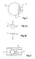
- Fig. 1 shows an optical receiver lens 1 for a in Fig. 3
- a rangefinder 2 designed as a laser rangefinder.
- a three-dimensional lens surface 3 facing the reflective object, the distance of which is to be determined by the rangefinder 2 comprises a spherical section 4, left in the plane of the drawing, not adjacent thereto in the plane of the drawing -spherical surface section 5 for medium distances and a non-spherical surface section 6 adjoining the latter surface section 5 for short distances.
- the surface sections identified by the reference numeral 7 have no receiving function.
- a receiver lens 1 in a three-dimensional, three mutually perpendicular axes (x, y, z) comprising, coordinate system can be seen. It can be seen that the x-axis and the y-axis characterize the areal extent of the lens surface 3, whereas the z-axis, which is perpendicular to the surface extent of the lens surface, coincides with the optical axis of the receiver lens 1.
- the receiver lens 1 is arranged to the left of a lens 8 of a transmission beam path, resulting in a not shown, known per se parallax angle between the transmission beam path and a through the receiver lens 1 radiating receiving beam path leads.
- Fig. 4a shows a diagram in which the ordinate logarhythmically a ratio v, from an optical power received by the receiver lens 1 and an optical power received by a photodetector is plotted and in which the distance is plotted logarithmically on the abscissa.
- the ratio value V in the logarithmic representation increases linearly with slope 2, ideally up to 100% (in practice less than 100%, but greater than 90%) and then remains constant.
- the optical power P of the photodetector is initially constant, that is to say constant in the near range and decreases at a certain distance value.
- the deflection along the z-axis in a receiver lens formed according to the concept of the invention can be determined by the addition of a first function f 1 (x + y) and a second function f 2 (x). So as the sum of a first function that depends on x 2 + y 2 and a second function that depends exclusively on x and not on y.
- the second function f 2 (x) can be defined, for example, by N piece-by-piece connected functions: f 2 x ⁇ f 2 . 1 x ⁇ x ⁇ x 0 K x 1 M f 2 . N x ⁇ x ⁇ x N - 1 K x N . wherein the pieces-by-piece functional sections f 2, i are given by second-order polynomials: f 2 . i x ⁇ a i . 0 + a i . 1 ⁇ x + a i . 2 ⁇ x 2 ,
- N -2 parameters are available as optimization parameters for the lens design.
Landscapes
- Physics & Mathematics (AREA)
- Engineering & Computer Science (AREA)
- General Physics & Mathematics (AREA)
- Radar, Positioning & Navigation (AREA)
- Remote Sensing (AREA)
- Electromagnetism (AREA)
- Computer Networks & Wireless Communication (AREA)
- Optical Radar Systems And Details Thereof (AREA)
- Lenses (AREA)
Description
- Die Erfindung betrifft eine optische Empfängerlinse mit einer dreidimensionalen Linsenoberfläche gemäß dem Oberbegriff des Anspruchs 1 sowie einen optischen Entfernungsmesser, insbesondere einen Laser-Entfernungsmesser, gemäß Anspruch 5.
- Verschiedenartige optische Entfernungsmesser sind in der
US 2007/0030474 A1 , derWO 03/002939 A1 DE 10 051 302 C5 , derWO 2005/064359 A1 , derEP 00 701 702 B WO 2006/024566 A1 und derDE 43 16 348 A1 beschrieben. - Schwierigkeiten bei der Auslegung von Empfängeroptiken für Entfernungsmesser bereitet die Vorgabe, dass die Entfernungsmesser sowohl zum präzisen Messen im Nah- als auch im Fernbereich einsetzbar sein sollen. Probleme beim Messen von großen Entfernungen bereiten Fremdlichteinflüsse, die sich negativ auf das Signal-Rausch-Verhältnis auswirken. Üblicherweise wird zur Reduzierung des Fremdlichteinflusses die Größe des zum Einsatz kommenden Fotodetektors so gut wie möglich auf die Größe des von weit entfernten Objekten reflektierten Lichtpunktes abgestimmt. Bei Nahfeldmessungen besteht u.a. das Problem, dass sich ein Parallaxwinkel zwischen einem ausgesendeten Lichtstrahl und einem empfangenen Lichtstrah vergleichsweise stark auf das Messergebnis auswirkt. Der Parallaxwinkel ist darauf zurückzuführen, dass das Sendelinsensystem benachbart zum Empfängerlinsensystem angeordnet ist. Ein weiteres, wesentliches Problem bei der Auslegung von Entfernungsmessern, die sowohl für den Nah- als auch für den Fernbereich einsetzbar sein sollen, besteht darin, dass bei großen Entfernungen, die empfangene optische Leistung proportional zur inversen Distanz im Quadrat ist. Dies resultiert in der Notwendigkeit das Empfangssystem zum Verarbeiten schwacher Signale auszulegen. Die starke Zunahme der empfangenen Laserleistung bei kurzen Entfernungen führt zur selben Zeit jedoch dazu, dass das Empfangssystem vergleichsweise ineffizient für kurze Entfernungen ausgelegt werden muss, um eine Sättigung der elektronischen Detektionsschaltung zu verhindern.
- Der Erfindung liegt die Aufgabe zugrunde, eine Empfängerlinse vorzuschlagen, die sowohl für den Messeinsatz im Nah- als auch im Fernbereich geeignet ist. Ferner besteht die Aufgabe darin, einen optischen Entfernungsmesser mit einer entsprechend verbesserten optischen Empfängerlinse bereitzustellen.
- Diese Aufgabe wird hinsichtlich der optischen Empfängerlinse mit den Merkmalen des Anspruchs 1 und hinsichtlich des optischen Entfernungsmessers mit den Merkmalen des Anspruchs 5 gelöst. Vorteilhafte Weiterbildungen der Erfindung sind in den abhängigen Ansprüchen angegeben.
- Der Erfindung liegt der Gedanke zugrunde, zumindest einen nicht-sphärischen Flächenabschnitt der Linsenoberfläche, vorzugsweise einen nicht-sphärischen Flächenabschnitt einer dem reflektierenden Objekt zugewandten Linsenoberfläche, derart auszubilden, dass dieser durch Addition von mindestens zwei, vorzugsweise von ausschließlich zwei, Flächen erhalten wird, nämlich einer ersten Fläche, deren Durchbiegung entlang der z-Achse, also deren Erstreckung entlang der z-Achse sowohl eine Funktion von x und y, insbesondere des Radiuses (r2=x2+y2) und einer zweiten Fläche, deren Durchbiegung entlang der z-Achse ausschließlich eine Funktion von x, d.h. nicht von y ist. Besonders bevorzugt wird der nicht-sphärische Flächenabschnitt dabei derart ausgebildet, dass das Verhältnis zwischen der von der optischen Empfängerlinse empfangenen optischen Leistung und der von einem Fotodetektor erfassten optischen Leistung mit zunehmendem Abstand ansteigt, bis ein konstantes Verhältnis, von vorzugsweise über 90% erreicht wird. Dies führt dazu, dass die optische Leistung auf dem Fotodetektor, d.h. die Detektorschaltung auch im Nahbereich nicht gesättigt ist und zu geringeren Distanzen hin abnimmt. Ein mit einer nach dem Konzept der Erfindung ausgebildeten optischen Empfängerlinse ausgestatteter Entfernungsmes-ser zeichnet sich durch ein optimiertes Signal-Rausch-Verhältnis aus. Die Empfängerlinse zeichnet sich ferner durch die Möglichkeit zum Einsatz für Messungen im Nah- sowie im Fernbereich aus. Insbesondere kann eine gute, stabile Signalamplitude auch bei kurzen Entfernungsmessungen ohne weiteren Aufwand erhalten werden. Darüber hinaus besteht die Möglichkeit die Empfängerlinse kostengünstig aus Kunststoff auszubilden. Ferner wirkt sich ein bevorzugt realisierter Parallaxwinkel zwischen einem Empfängerstrahlengang und einem Sendestrahlengang nur unwesentlich auf das Messergebnis aus.
- In Weiterbildung der Erfindung ist mit Vorteil vorgesehen, dass die die Durchbiegung der ersten Fläche entlang der z-Achse beschreibende erste Funktion und/oder die die Durchbiegung der zweiten Fläche entlang der z-Achse beschreibende zweite Funktion mindestens einfach stetig differenzierbar ist/sind. Hierdurch kann die Linsenoberfläche vereinfacht gefertigt werden. Besonders vorteilhaft ist es, wenn die die Durchbiegung beschreibenden Funktionen mindestens zweifach stetig differenzierbar sind.
- In Weiterbildung der Erfindung ist mit Vorteil vorgesehen, dass zusätzlich zu der ersten und der zweiten Funktion zur Beschreibung des nicht-sphärischen Flächenabschnittes oder eines Unterflächenabschnitts des nicht-sphärischen Flächenabschnitts mindestens eine dritte Fläche addierbar ist, deren Durchbiegung entlang der z-Achse durch eine dritte Funktion beschreibbar ist, beispielsweise durch eine von x und y abhängige Funktion, wie z.B.:

- Ganz besonders bevorzugt ist es, wenn der wie zuvor beschrieben ausgebildete nicht-sphärische Flächenabschnitt der Linsenoberfläche auf einer dem reflektierenden Objekt zugewandten Empfängerlinsenseite angeordnet ist.
- Die Erfindung führt auch auf einen optischen Entfernungsmesser, insbesondere einen Laser-Entfernungsmesser mit einer wie zuvor beschrieben ausgebildeten optischen Empfängerlinse. Der optische Entfernungsmesser kann in an sich bekannter Weise auf Basis interferrometrischer Messungen und/oder auf Basis von Laufzeitmessungen arbeitend ausgebildet sein.
- Bevorzugt ist eine Ausführungsform des Entfernungsmessers, bei der die optische Empfängerlinse die einzige Empfängerlinse im Empfangsstrahlengang ist. Ganz besonders bevorzugt sind zusätzlich zu der einzigen Empfängerlinse keine weiteren optischen Elemente, wie Spiegel, etc. vorgesehen.
- Besonders bevorzugt ist eine Ausführungsform des Entfernungsmessers, bei der der Empfangsstrahlengang unter einem Parallaxwinkel zu einem Sendestrahlengang angeordnet ist, wobei der Sendestrahlengang ganz besonders bevorzugt von der x-Achse des die Empfangslinse beschreibenden, dreidimensionalen Koordinatensystems senkrecht geschnitten wird.
- Weitere Vorteile, Merkmale und Einzelheiten der Erfindung ergeben sich aus der nachfolgenden Beschreibung bevorzugter Ausführungsbeispiele sowie anhand der Zeichnungen.
- Diese zeigen in:
- Fig. 1:
- eine Draufsicht auf eine dreidimensionale, einem nicht gezeigten reflektierenden Objekt zugewandten, Linsenoberfläche einer optischen Empfängerlinse,
- Fig. 2a u. Fig. 2b:
- zwei um 90° gedrehte Ansichten einer optischen Empfängerlinse, wobei aus den Ansichten die Lage eines dreidimensionalen Koordinatensystems mit den Achsen x, y und z deutlich wird,
- Fig. 3:
- eine mögliche Anordnung einer optischen Empfängerlinse in einem Entfernungsmesser,
- Fig. 4a:
- ein Diagramm, in dem das Verhältnis aus der von der optischen Empfängerlinse empfangenen optischen Leistung und der von einem Fotodetektor erfassten optischen Leistung über die zu messende Entfernung aufgetragen ist,
- Fig. 4b:
- ein weiteres Diagramm, das die auf dem Fotodetektor auftreffende optische Leistung über die zu messenden Entfernung zeigt,
- Fig. 5:
- eine optische Linse mit einem nicht-sphärischen Flächenabschnitt und
- Fig. 6:
- eine Beschreibung einer zweiten, ausschließlich von x abhängigen Funktion durch stückweise aneinandergehängte Polynome zweiter Ordnung.
-
Fig. 1 zeigt eine optische Empfängerlinse 1 für einen inFig. 3 dargestellten, als Laser-Entfernungsmesser ausgebildeten Entfernungsmesser 2. Eine dem reflektierenden nicht gezeigten Objekt, dessen Entfernung mittels des Entfernungsmessers 2 bestimmt werden soll, zugewandte dreidimensionale Linsenoberfläche 3 umfasst einen in der Zeichnungsebene linken, sphärischen Abschnitt 4, einen in der Zeichnungsebene rechts daran angrenzenden nicht-sphärischen Flächenabschnitt 5 für mittlere Distanzen und einen wiederum an letzteren Flächenabschnitt 5 angrenzenden, nicht-sphärischen Flächenabschnitt 6 für kurze Distanzen. Die mit dem Bezugszeichen 7 gekennzeichneten Flächenabschnitte haben keine Empfangsfunktion. - Aus den
Fig. 2a und 2b ist die Lage einer Empfängerlinse 1 in einem dreidimensionalen, drei rechtwinklig zueinander verlaufende Achsen (x, y, z) umfassenden, Koordinatensystem ersichtlich. Zu erkennen ist, dass die x-Achse und die yAchse die Flächenerstreckung der Linsenoberfläche 3 charakterisieren, wohingegen die z-Achse, die senkrecht auf der Flächenerstreckung der Linsenoberfläche steht mit der optischen Achse der Empfängerlinse 1 zusammenfällt. - Aus
Fig. 3 ergibt sich eine mögliche Anordnung der vorzugsweise aus Kunststoff ausgebildeten Empfängerlinse 1 in einem Entfernungsmesser 2. Zu erkennen ist, dass die Empfängerlinse 1 links neben einer Linse 8 eines Sendestrahlengangs angeordnet ist, was zu einem nicht eingezeichneten, an sich bekannten Parallaxwinkel zwischen dem Sendestrahlengang und einem durch die Empfängerlinse 1 strahlenden Empfangsstrahlengang führt. -
Fig. 4a zeigt ein Diagramm, bei dem auf der Ordinate logarhythmisch ein Verhältniswert v, aus einer von der Empfängerlinse 1 empfangenden optischen Leistung und einer von einem Fotodetektor empfangenen optischen Leistung aufgetragen ist und in dem auf der Abszisse logarhythmisch die Entfernung aufgetragen ist. Zu erkennen ist, dass der Verhältniswert V in der logarhythmischen Darstellung linear mit der Steigung 2 ansteigt, idealerweise bis auf 100% (in der Praxis kleiner als 100%, jedoch größer als 90%) und dann konstant bleibt. Hieraus resultiert, wie aus dem Diagramm gemäßFig. 4b zu entnehmen ist, dass die optische Leistung P des Fotodetektors zunächst, d.h. im Nahbereich konstant ist und ab einem bestimmten Distanzwert abnimmt. Auch bei dem Diagramm gem.Fig. 4b handelt es sich um logarhythmische Koordinatenachsen. - Allgemein ist festzuhalten, dass sich die Durchbiegung entlang der z-Achse bei einer nach dem Konzept der Erfindung ausgebildeten Empfängerlinse bestimmen lässt durch die Addition einer ersten Funktion f1(x+y) und einer zweiten Funktion f2(x). Also als Summe einer ersten Funktion, die abhängig ist von

- Anhand der
Fig. 5 und6 wird im Folgenden ein Beispiel für eine erste und eine zweite Funktion erläutert. Durch Addition dieser Funktionen f1, f2 ist die Durchbiegung des inFig. 5 mit dem Bezugszeichen 9 gekennzeichneten nichtsphärischen Flächenabschnitts entlang der z-Achse beschrieben. In der Zeichnungsebene links neben dem nicht sphärischen Flächenabschnitt 9 befindet sich ein sphärischer Flächenabschnitt 4 für den Fernbereich. - Gemäß einer bevorzugten Ausführungsform lautet die erste Funktion

- Die Variable r2 (r=Radius) kann substituiert werden durch x2+y2.
- In der ersten Funktion f1 sind:
- d:
- ein Linsendickenparameter,
- R0:
- ein sphärischer Parameter des Basis-Krümmungsradius der Linsenoberfläche
- e:
- ein konischer Parameter und
- z1:
- die Durchbiegung der ersten Fläche entlang des Abstands vom Vertex der Linse in der x-y-Ebene.
- Die zweite Funktion f2 lautet:

- Die zweite Funktion f2(x) kann beispielsweise durch N stückweise aneinandergehängte Funktionen definiert werden:


- Die Forderung, dass die auf diese Weise zusammengesetzte Funktion f2(x) mindestens einmal stetig differenzierbar ist, führt auf folgende 2(N+1) Bedingungen:


- Die verbleibenden N-2 Parameter stehen als Optimierungsparameter für das Linsendesign zur Verfügung.
- Die Durchbiegung des nicht-sphärischen Flächenabschnitts 9 wird also erhalten durch Addition der Durchbiegungen z1 und z2 der ersten und zweiten Fläche:

Claims (8)
- Optische Empfängerlinse mit einer dreidimensionalen Linsenoberfläche (3), zum Empfangen der an einem Objekt reflektierten Laserstrählung eines Laserentfernungsmessers (2), wobei die Empfängerlinse (1) in einem dreidimensionalen, drei rechtwinklig zueinander angeordnete Achsen x, y, z aufweisenden Koordinatensystem beschreibbar ist, und wobei die z-Achse mit der optischen Achse der Empfängerlinse (1) zusammen fällt, dadurch gekennzeichnet, dass die dreidimensionale Linsenoberfläche (3) mehrere Flächenabschnitte aufweist, wobei die Durchbiegung entlang der z-Achse zumindest eines nichtsphärischen Flächenabschnitts (9) der dreidimensionalen Linsenoberfläche (3) beschreibbar ist durch Addition einer ersten Funktion f1, die abhängig ist von √(x 2 + y 2), und einer zweiten Funktion f2, die ausschließlich von x und nicht von y abhängig ist.
- Optische Empfängerlinse nach Anspruch 1,
dadurch gekennzeichnet,
dass die erste und/oder die zweite Funktion (f1, f2) mindestens einfach stetig differenzierbar ist/sind. - Optische Empfängerlinse nach einem der vorhergehenden Ansprüche,
dadurch gekennzeichnet,
dass der nicht-sphärische Flächenabschnitt (9) der Linsenoberfläche (3) oder ein Unterflächenabschnitt des nicht-sphärischen Flächenabschnitts (9) beschreibbar ist durch zusätzliche Addition einer dritten Fläche deren Durchbiegung entlang der z-Achse eine dritte Funktion, insbesondere von x und/oder y, ist. - Optische Empfängerlinse nach einem der vorhergehenden Ansprüche,
dadurch gekennzeichnet,
dass der nicht-sphärische Flächenabschnitt (9) auf einer dem reflektierenden Objekt zugewandten Empfängerlinsenseite angeordnet ist. - Optischer Entfernungsmesser, insbesondere Laser-Entfernungsmesser, mit einer optischen Empfängerlinse (1) nach einem der vorhergehenden Ansprüche.
- Optischer Entfernungsmesser nach Anspruch 5,
dadurch gekennzeichnet,
dass die optische Empfängerlinse (1) die einzige Empfängerlinse (1) und/oder das einzige optische Element im Empfangsstrahlengang ist. - Optischer Entfernungsmesser nach einem der Ansprüche 5 oder 6,
dadurch gekennzeichnet,
dass der Empfangsstrahlengang unter einem Parallaxwinkel zu einem Sendestrahlengang angeordnet ist. - Optischer Entfernungsmesser nach Anspruch 7,
dadurch gekennzeichnet,
dass die optische Empfängerlinse (1) derart angeordnet ist, dass der Sendestrahlengang von der x-Achse geschnitten wird.
Applications Claiming Priority (2)
| Application Number | Priority Date | Filing Date | Title |
|---|---|---|---|
| DE102008054790A DE102008054790A1 (de) | 2008-12-17 | 2008-12-17 | Optische Empfängerlinse sowie optischer Entfernungsmesser |
| PCT/EP2009/063699 WO2010069633A1 (de) | 2008-12-17 | 2009-10-20 | Optische empfängerlinse sowie optischer entfernungsmesser |
Publications (2)
| Publication Number | Publication Date |
|---|---|
| EP2379983A1 EP2379983A1 (de) | 2011-10-26 |
| EP2379983B1 true EP2379983B1 (de) | 2015-06-03 |
Family
ID=41437728
Family Applications (1)
| Application Number | Title | Priority Date | Filing Date |
|---|---|---|---|
| EP09740110.3A Active EP2379983B1 (de) | 2008-12-17 | 2009-10-20 | Optische empfängerlinse sowie optischer entfernungsmesser |
Country Status (5)
| Country | Link |
|---|---|
| US (1) | US8611022B2 (de) |
| EP (1) | EP2379983B1 (de) |
| CN (1) | CN102257355B (de) |
| DE (1) | DE102008054790A1 (de) |
| WO (1) | WO2010069633A1 (de) |
Cited By (1)
| Publication number | Priority date | Publication date | Assignee | Title |
|---|---|---|---|---|
| WO2021083702A1 (de) | 2019-10-30 | 2021-05-06 | Robert Bosch Gmbh | Nivellierlaser sowie optische projektionslinse |
Families Citing this family (3)
| Publication number | Priority date | Publication date | Assignee | Title |
|---|---|---|---|---|
| US9686021B2 (en) | 2011-03-30 | 2017-06-20 | Schlumberger Technology Corporation | Wireless network discovery and path optimization algorithm and system |
| CN104266598A (zh) * | 2014-10-06 | 2015-01-07 | 上海工程技术大学 | 一种检测地铁站台屏蔽门与车体距离是否安全的方法 |
| CN106997091B (zh) * | 2017-05-24 | 2019-08-27 | 湖北三江航天万峰科技发展有限公司 | 一种激光测角镜头光学系统 |
Family Cites Families (17)
| Publication number | Priority date | Publication date | Assignee | Title |
|---|---|---|---|---|
| US4418992A (en) * | 1982-05-17 | 1983-12-06 | Younger Manufacturing Company | Ophthalmic progressive power lens and method of making same |
| US4838675A (en) * | 1987-06-19 | 1989-06-13 | Sola International Holdings, Ltd. | Method for improving progressive lens designs and resulting article |
| DE4316348A1 (de) | 1993-05-15 | 1994-11-17 | Wild Heerbrugg Ag | Vorrichtung zur Distanzmessung |
| US5691798A (en) * | 1995-07-27 | 1997-11-25 | Teijin Chemicals Ltd. | Progressive power ophthalmic lens |
| DE19804059B4 (de) * | 1998-02-03 | 2006-02-09 | Robert Bosch Gmbh | Vorrichtung zur optischen Distanzmessung |
| US6368763B2 (en) * | 1998-11-23 | 2002-04-09 | U.S. Philips Corporation | Method of detecting aberrations of an optical imaging system |
| US6220703B1 (en) * | 1999-12-29 | 2001-04-24 | Younger Manufacturing Co., Inc. | Ophthalmic lenses utilizing polyethylene terephthalate polarizing films |
| DE10051302C5 (de) | 2000-10-13 | 2007-12-27 | Jenoptik Ag | Laserentfernungsmessgerät für den Nah- und Fernbereich mit speziellem Empfänger |
| JP4349550B2 (ja) * | 2001-03-29 | 2009-10-21 | フジノン株式会社 | 反射型投映用光学系 |
| DE10130763A1 (de) | 2001-06-26 | 2003-01-02 | Bosch Gmbh Robert | Vorrichtung zur optischen Distanzmessung über einen grossen Messbereich |
| CN1894593B (zh) | 2003-12-19 | 2010-04-28 | 莱卡地球系统公开股份有限公司 | 测量至远处和近处目标的距离的装置 |
| CN1677126A (zh) * | 2004-04-01 | 2005-10-05 | 亚洲光学股份有限公司 | 激光测距仪的光学系统 |
| DE102004042466A1 (de) | 2004-09-02 | 2006-03-23 | Robert Bosch Gmbh | Vorrichtung und Verfahren zur optischen Distanzmessung |
| DE102005007945A1 (de) * | 2005-02-22 | 2006-08-24 | Adc Automotive Distance Control Systems Gmbh | Optische Linse |
| CN2811945Y (zh) * | 2005-08-08 | 2006-08-30 | 南京德朔实业有限公司 | 光学测距装置 |
| DE102005043418A1 (de) * | 2005-09-13 | 2007-03-22 | Robert Bosch Gmbh | Elektro-optisches Messgerät |
| EP1959281B1 (de) * | 2007-02-13 | 2010-01-20 | Konica Minolta Opto, Inc. | Optische Kopplungslinse und Lichtquelle |
-
2008
- 2008-12-17 DE DE102008054790A patent/DE102008054790A1/de not_active Ceased
-
2009
- 2009-10-20 EP EP09740110.3A patent/EP2379983B1/de active Active
- 2009-10-20 CN CN200980150684.0A patent/CN102257355B/zh active Active
- 2009-10-20 US US13/140,420 patent/US8611022B2/en not_active Expired - Fee Related
- 2009-10-20 WO PCT/EP2009/063699 patent/WO2010069633A1/de not_active Ceased
Cited By (2)
| Publication number | Priority date | Publication date | Assignee | Title |
|---|---|---|---|---|
| WO2021083702A1 (de) | 2019-10-30 | 2021-05-06 | Robert Bosch Gmbh | Nivellierlaser sowie optische projektionslinse |
| US12352573B2 (en) | 2019-10-30 | 2025-07-08 | Robert Bosch Gmbh | Levelling laser and optical projection lens |
Also Published As
| Publication number | Publication date |
|---|---|
| US8611022B2 (en) | 2013-12-17 |
| WO2010069633A1 (de) | 2010-06-24 |
| DE102008054790A1 (de) | 2010-07-01 |
| CN102257355B (zh) | 2014-12-03 |
| EP2379983A1 (de) | 2011-10-26 |
| CN102257355A (zh) | 2011-11-23 |
| US20120013918A1 (en) | 2012-01-19 |
Similar Documents
| Publication | Publication Date | Title |
|---|---|---|
| DE2834821C2 (de) | Einrichtung zum Überprüfen der Betriebseigenschaften von Laser-Entfernungsmeßgeräten | |
| EP3168642B1 (de) | Optoelektronischer sensor und verfahren zur erfassung eines objekts | |
| DE10035263C2 (de) | Optische Vorrichtung | |
| EP2458363A1 (de) | Messung der Positionen von Krümmungsmittelpunkten optischer Flächen eines mehrlinsigen optischen Systems | |
| EP2379983B1 (de) | Optische empfängerlinse sowie optischer entfernungsmesser | |
| WO2015027994A1 (de) | Messvorrichtung für reflexionsmessungen an prüfobjekten sowie verfahren zur messung von an prüfobjekten reflektierter strahlung | |
| DE102017205981A1 (de) | Messvorrichtung und Messverfahren zur Überwachung einer Flüssigkeit in einem Flüssigkeitstank sowie Flüssigkeitstank | |
| EP1695109B1 (de) | Vorrichtung zum messen der distanz zu fernen und nahen objekten | |
| WO1986004676A2 (en) | Device for optical determination of low-order errors in shape | |
| DE19902287B4 (de) | Verfahren und Anordnung zur automatischen Justage eines Laserscanner-Sensors | |
| EP1624278B1 (de) | Luftfeder mit einer Messeinrichtung zur Abstands-Bestimmung von Kraftfahrzeugteilen | |
| DE10141363A1 (de) | Vorrichtung zur Abtastung einer Szene | |
| EP2981809B1 (de) | Vorrichtung zur messung der streuung einer probe | |
| DE10160299A1 (de) | Verfahren und System zum Detektieren mindestens eines Objekts | |
| DE3311945C2 (de) | Vorrichtung zur berührungslosen Messung von Winkeln | |
| DE102013219830A1 (de) | Optische Vorrichtung zur Reflexionsmessung unter diffuser Beleuchtung und Verfahren zum Optimieren einer solchen | |
| DE10147987A1 (de) | Optoelektronisches Bauelement | |
| DE202013003898U1 (de) | Goniometer für optische Prismen | |
| DE69805598T2 (de) | Vorrichtung zur Messung von Abstand oder Einfallswinkel eines Lichtstrahls | |
| DE102018119412A1 (de) | Optische Baugruppe sowie Verfahren zur Herstellung einer optischen Baugruppe | |
| DE4102990C2 (de) | ||
| WO1994000778A1 (de) | Verfahren zur messung von relativen winkeln | |
| DE102005009424A1 (de) | Optischer Sensor mit optimierter Sensitivität | |
| AT506773B1 (de) | Verfahren und vorrichtung zur messung des füllstandes einer flüssigkeit in einem hohlraum mit sub-mm breiter öffnung | |
| EP1323170B1 (de) | Röntgenoptische anordnung |
Legal Events
| Date | Code | Title | Description |
|---|---|---|---|
| PUAI | Public reference made under article 153(3) epc to a published international application that has entered the european phase |
Free format text: ORIGINAL CODE: 0009012 |
|
| 17P | Request for examination filed |
Effective date: 20110718 |
|
| AK | Designated contracting states |
Kind code of ref document: A1 Designated state(s): AT BE BG CH CY CZ DE DK EE ES FI FR GB GR HR HU IE IS IT LI LT LU LV MC MK MT NL NO PL PT RO SE SI SK SM TR |
|
| DAX | Request for extension of the european patent (deleted) | ||
| 17Q | First examination report despatched |
Effective date: 20120502 |
|
| GRAP | Despatch of communication of intention to grant a patent |
Free format text: ORIGINAL CODE: EPIDOSNIGR1 |
|
| INTG | Intention to grant announced |
Effective date: 20150219 |
|
| GRAS | Grant fee paid |
Free format text: ORIGINAL CODE: EPIDOSNIGR3 |
|
| GRAA | (expected) grant |
Free format text: ORIGINAL CODE: 0009210 |
|
| AK | Designated contracting states |
Kind code of ref document: B1 Designated state(s): AT BE BG CH CY CZ DE DK EE ES FI FR GB GR HR HU IE IS IT LI LT LU LV MC MK MT NL NO PL PT RO SE SI SK SM TR |
|
| REG | Reference to a national code |
Ref country code: GB Ref legal event code: FG4D Free format text: NOT ENGLISH |
|
| REG | Reference to a national code |
Ref country code: CH Ref legal event code: EP |
|
| REG | Reference to a national code |
Ref country code: AT Ref legal event code: REF Ref document number: 730139 Country of ref document: AT Kind code of ref document: T Effective date: 20150715 Ref country code: IE Ref legal event code: FG4D Free format text: LANGUAGE OF EP DOCUMENT: GERMAN |
|
| REG | Reference to a national code |
Ref country code: DE Ref legal event code: R096 Ref document number: 502009011100 Country of ref document: DE |
|
| REG | Reference to a national code |
Ref country code: FR Ref legal event code: PLFP Year of fee payment: 7 |
|
| PG25 | Lapsed in a contracting state [announced via postgrant information from national office to epo] |
Ref country code: LT Free format text: LAPSE BECAUSE OF FAILURE TO SUBMIT A TRANSLATION OF THE DESCRIPTION OR TO PAY THE FEE WITHIN THE PRESCRIBED TIME-LIMIT Effective date: 20150603 Ref country code: FI Free format text: LAPSE BECAUSE OF FAILURE TO SUBMIT A TRANSLATION OF THE DESCRIPTION OR TO PAY THE FEE WITHIN THE PRESCRIBED TIME-LIMIT Effective date: 20150603 Ref country code: HR Free format text: LAPSE BECAUSE OF FAILURE TO SUBMIT A TRANSLATION OF THE DESCRIPTION OR TO PAY THE FEE WITHIN THE PRESCRIBED TIME-LIMIT Effective date: 20150603 Ref country code: NO Free format text: LAPSE BECAUSE OF FAILURE TO SUBMIT A TRANSLATION OF THE DESCRIPTION OR TO PAY THE FEE WITHIN THE PRESCRIBED TIME-LIMIT Effective date: 20150903 Ref country code: ES Free format text: LAPSE BECAUSE OF FAILURE TO SUBMIT A TRANSLATION OF THE DESCRIPTION OR TO PAY THE FEE WITHIN THE PRESCRIBED TIME-LIMIT Effective date: 20150603 |
|
| REG | Reference to a national code |
Ref country code: NL Ref legal event code: MP Effective date: 20150603 |
|
| REG | Reference to a national code |
Ref country code: LT Ref legal event code: MG4D |
|
| PG25 | Lapsed in a contracting state [announced via postgrant information from national office to epo] |
Ref country code: BG Free format text: LAPSE BECAUSE OF FAILURE TO SUBMIT A TRANSLATION OF THE DESCRIPTION OR TO PAY THE FEE WITHIN THE PRESCRIBED TIME-LIMIT Effective date: 20150903 Ref country code: GR Free format text: LAPSE BECAUSE OF FAILURE TO SUBMIT A TRANSLATION OF THE DESCRIPTION OR TO PAY THE FEE WITHIN THE PRESCRIBED TIME-LIMIT Effective date: 20150904 Ref country code: LV Free format text: LAPSE BECAUSE OF FAILURE TO SUBMIT A TRANSLATION OF THE DESCRIPTION OR TO PAY THE FEE WITHIN THE PRESCRIBED TIME-LIMIT Effective date: 20150603 |
|
| PG25 | Lapsed in a contracting state [announced via postgrant information from national office to epo] |
Ref country code: EE Free format text: LAPSE BECAUSE OF FAILURE TO SUBMIT A TRANSLATION OF THE DESCRIPTION OR TO PAY THE FEE WITHIN THE PRESCRIBED TIME-LIMIT Effective date: 20150603 |
|
| PG25 | Lapsed in a contracting state [announced via postgrant information from national office to epo] |
Ref country code: CZ Free format text: LAPSE BECAUSE OF FAILURE TO SUBMIT A TRANSLATION OF THE DESCRIPTION OR TO PAY THE FEE WITHIN THE PRESCRIBED TIME-LIMIT Effective date: 20150603 Ref country code: RO Free format text: LAPSE BECAUSE OF NON-PAYMENT OF DUE FEES Effective date: 20150603 Ref country code: PL Free format text: LAPSE BECAUSE OF FAILURE TO SUBMIT A TRANSLATION OF THE DESCRIPTION OR TO PAY THE FEE WITHIN THE PRESCRIBED TIME-LIMIT Effective date: 20150603 Ref country code: SK Free format text: LAPSE BECAUSE OF FAILURE TO SUBMIT A TRANSLATION OF THE DESCRIPTION OR TO PAY THE FEE WITHIN THE PRESCRIBED TIME-LIMIT Effective date: 20150603 Ref country code: IS Free format text: LAPSE BECAUSE OF FAILURE TO SUBMIT A TRANSLATION OF THE DESCRIPTION OR TO PAY THE FEE WITHIN THE PRESCRIBED TIME-LIMIT Effective date: 20151003 Ref country code: PT Free format text: LAPSE BECAUSE OF FAILURE TO SUBMIT A TRANSLATION OF THE DESCRIPTION OR TO PAY THE FEE WITHIN THE PRESCRIBED TIME-LIMIT Effective date: 20151006 |
|
| REG | Reference to a national code |
Ref country code: DE Ref legal event code: R097 Ref document number: 502009011100 Country of ref document: DE |
|
| PLBE | No opposition filed within time limit |
Free format text: ORIGINAL CODE: 0009261 |
|
| STAA | Information on the status of an ep patent application or granted ep patent |
Free format text: STATUS: NO OPPOSITION FILED WITHIN TIME LIMIT |
|
| PG25 | Lapsed in a contracting state [announced via postgrant information from national office to epo] |
Ref country code: DK Free format text: LAPSE BECAUSE OF FAILURE TO SUBMIT A TRANSLATION OF THE DESCRIPTION OR TO PAY THE FEE WITHIN THE PRESCRIBED TIME-LIMIT Effective date: 20150603 Ref country code: IT Free format text: LAPSE BECAUSE OF FAILURE TO SUBMIT A TRANSLATION OF THE DESCRIPTION OR TO PAY THE FEE WITHIN THE PRESCRIBED TIME-LIMIT Effective date: 20150603 |
|
| 26N | No opposition filed |
Effective date: 20160304 |
|
| PG25 | Lapsed in a contracting state [announced via postgrant information from national office to epo] |
Ref country code: SI Free format text: LAPSE BECAUSE OF FAILURE TO SUBMIT A TRANSLATION OF THE DESCRIPTION OR TO PAY THE FEE WITHIN THE PRESCRIBED TIME-LIMIT Effective date: 20150603 Ref country code: LU Free format text: LAPSE BECAUSE OF FAILURE TO SUBMIT A TRANSLATION OF THE DESCRIPTION OR TO PAY THE FEE WITHIN THE PRESCRIBED TIME-LIMIT Effective date: 20151020 |
|
| REG | Reference to a national code |
Ref country code: CH Ref legal event code: PL |
|
| PG25 | Lapsed in a contracting state [announced via postgrant information from national office to epo] |
Ref country code: MC Free format text: LAPSE BECAUSE OF FAILURE TO SUBMIT A TRANSLATION OF THE DESCRIPTION OR TO PAY THE FEE WITHIN THE PRESCRIBED TIME-LIMIT Effective date: 20150603 |
|
| REG | Reference to a national code |
Ref country code: IE Ref legal event code: MM4A |
|
| PG25 | Lapsed in a contracting state [announced via postgrant information from national office to epo] |
Ref country code: LI Free format text: LAPSE BECAUSE OF NON-PAYMENT OF DUE FEES Effective date: 20151031 Ref country code: CH Free format text: LAPSE BECAUSE OF NON-PAYMENT OF DUE FEES Effective date: 20151031 |
|
| REG | Reference to a national code |
Ref country code: FR Ref legal event code: PLFP Year of fee payment: 8 |
|
| PG25 | Lapsed in a contracting state [announced via postgrant information from national office to epo] |
Ref country code: IE Free format text: LAPSE BECAUSE OF NON-PAYMENT OF DUE FEES Effective date: 20151020 |
|
| REG | Reference to a national code |
Ref country code: AT Ref legal event code: MM01 Ref document number: 730139 Country of ref document: AT Kind code of ref document: T Effective date: 20151020 |
|
| PG25 | Lapsed in a contracting state [announced via postgrant information from national office to epo] |
Ref country code: AT Free format text: LAPSE BECAUSE OF NON-PAYMENT OF DUE FEES Effective date: 20151020 |
|
| PG25 | Lapsed in a contracting state [announced via postgrant information from national office to epo] |
Ref country code: SM Free format text: LAPSE BECAUSE OF FAILURE TO SUBMIT A TRANSLATION OF THE DESCRIPTION OR TO PAY THE FEE WITHIN THE PRESCRIBED TIME-LIMIT Effective date: 20150603 Ref country code: HU Free format text: LAPSE BECAUSE OF FAILURE TO SUBMIT A TRANSLATION OF THE DESCRIPTION OR TO PAY THE FEE WITHIN THE PRESCRIBED TIME-LIMIT; INVALID AB INITIO Effective date: 20091020 |
|
| PG25 | Lapsed in a contracting state [announced via postgrant information from national office to epo] |
Ref country code: CY Free format text: LAPSE BECAUSE OF FAILURE TO SUBMIT A TRANSLATION OF THE DESCRIPTION OR TO PAY THE FEE WITHIN THE PRESCRIBED TIME-LIMIT Effective date: 20150603 Ref country code: SE Free format text: LAPSE BECAUSE OF FAILURE TO SUBMIT A TRANSLATION OF THE DESCRIPTION OR TO PAY THE FEE WITHIN THE PRESCRIBED TIME-LIMIT Effective date: 20150603 Ref country code: NL Free format text: LAPSE BECAUSE OF FAILURE TO SUBMIT A TRANSLATION OF THE DESCRIPTION OR TO PAY THE FEE WITHIN THE PRESCRIBED TIME-LIMIT Effective date: 20150603 |
|
| PG25 | Lapsed in a contracting state [announced via postgrant information from national office to epo] |
Ref country code: BE Free format text: LAPSE BECAUSE OF NON-PAYMENT OF DUE FEES Effective date: 20151031 |
|
| PG25 | Lapsed in a contracting state [announced via postgrant information from national office to epo] |
Ref country code: MT Free format text: LAPSE BECAUSE OF FAILURE TO SUBMIT A TRANSLATION OF THE DESCRIPTION OR TO PAY THE FEE WITHIN THE PRESCRIBED TIME-LIMIT Effective date: 20150603 Ref country code: TR Free format text: LAPSE BECAUSE OF FAILURE TO SUBMIT A TRANSLATION OF THE DESCRIPTION OR TO PAY THE FEE WITHIN THE PRESCRIBED TIME-LIMIT Effective date: 20150603 |
|
| REG | Reference to a national code |
Ref country code: FR Ref legal event code: PLFP Year of fee payment: 9 |
|
| PG25 | Lapsed in a contracting state [announced via postgrant information from national office to epo] |
Ref country code: MK Free format text: LAPSE BECAUSE OF FAILURE TO SUBMIT A TRANSLATION OF THE DESCRIPTION OR TO PAY THE FEE WITHIN THE PRESCRIBED TIME-LIMIT Effective date: 20150603 |
|
| REG | Reference to a national code |
Ref country code: FR Ref legal event code: PLFP Year of fee payment: 10 |
|
| PGFP | Annual fee paid to national office [announced via postgrant information from national office to epo] |
Ref country code: FR Payment date: 20221020 Year of fee payment: 14 |
|
| PGFP | Annual fee paid to national office [announced via postgrant information from national office to epo] |
Ref country code: GB Payment date: 20221024 Year of fee payment: 14 |
|
| GBPC | Gb: european patent ceased through non-payment of renewal fee |
Effective date: 20231020 |
|
| PG25 | Lapsed in a contracting state [announced via postgrant information from national office to epo] |
Ref country code: GB Free format text: LAPSE BECAUSE OF NON-PAYMENT OF DUE FEES Effective date: 20231020 |
|
| PG25 | Lapsed in a contracting state [announced via postgrant information from national office to epo] |
Ref country code: GB Free format text: LAPSE BECAUSE OF NON-PAYMENT OF DUE FEES Effective date: 20231020 Ref country code: FR Free format text: LAPSE BECAUSE OF NON-PAYMENT OF DUE FEES Effective date: 20231031 |
|
| PGFP | Annual fee paid to national office [announced via postgrant information from national office to epo] |
Ref country code: DE Payment date: 20251209 Year of fee payment: 17 |