EP2380182B1 - Commutateur électrique - Google Patents
Commutateur électrique Download PDFInfo
- Publication number
- EP2380182B1 EP2380182B1 EP10706900.7A EP10706900A EP2380182B1 EP 2380182 B1 EP2380182 B1 EP 2380182B1 EP 10706900 A EP10706900 A EP 10706900A EP 2380182 B1 EP2380182 B1 EP 2380182B1
- Authority
- EP
- European Patent Office
- Prior art keywords
- contact
- contact system
- actuating member
- switching
- electric motor
- Prior art date
- Legal status (The legal status is an assumption and is not a legal conclusion. Google has not performed a legal analysis and makes no representation as to the accuracy of the status listed.)
- Active
Links
Images

Classifications
-
- H—ELECTRICITY
- H01—ELECTRIC ELEMENTS
- H01H—ELECTRIC SWITCHES; RELAYS; SELECTORS; EMERGENCY PROTECTIVE DEVICES
- H01H9/00—Details of switching devices, not covered by groups H01H1/00 - H01H7/00
- H01H9/02—Bases, casings, or covers
- H01H9/06—Casing of switch constituted by a handle serving a purpose other than the actuation of the switch, e.g. by the handle of a vacuum cleaner
- H01H9/061—Casing of switch constituted by a handle serving a purpose other than the actuation of the switch, e.g. by the handle of a vacuum cleaner enclosing a continuously variable impedance
Definitions
- the invention relates to an electrical switch according to the preamble of patent claim 1.
- Such switches are for power tools, such as hand-held power tools, such as electric drilling machines, rotary hammers, electric screwdriver o. The like., Used.
- the electrical energy from the network or a suitable battery system is converted or influenced so that a switch downstream electric motor of the power tool is controlled depending on the operator.
- the electric motor is switched on and / or off, braked, its speed changed or regulated torque and / or current dependent.
- the control device sets the speed of the power tool according to the adjustment made by the user of the actuator. If the actuator in the end position, so one of the bridging of the control device serving contact system is turned on, whereby the electric motor is operated at full voltage, the actuator thus acts in one position, namely when leaving the starting position and upon reaching the end position, switching on the respective contact system.
- a similar switch is also from the US Pat. No. 6,736,220 B1 known.
- the switch has a contact system consisting of a fixed contact and a switching contact.
- the switching contact is designed as a leaf spring with a punched-free spring tongue.
- the spring tongue cooperates with the pusher such that the switching contact switches with a snap action when pressing the pusher.
- this switch in which the on / off switching serving contact system is configured as a jump contact system, does not have a bridging contact system.
- the invention has for its object to further develop the electrical switch such that the reliability, especially in vibrating operation, is improved.
- the bridging contact system for the control device is designed as a jump contact system, with which the contact system switches over with a snap action.
- the actuator in the end position switching, so that this contact system is turned on to apply the full voltage to the electric motor. Since the full contact voltage for the power tool is thus applied to the bridging contact system, this provides particularly effective protection against premature destruction of this electrically highly loaded contact system.
- an electrical switch for power tools in the AC and / or DC range ie a power tool switch with control or regulating function in the nature of a "gas function", created a jump contact system for relief and / or to protect the bridging contact against stresses, in particular against teasing of the contact system.
- the switch may have a housing.
- the signaling device can cooperate with a control device for the power tool.
- the control device is used to operate the power tool, specifically for controlling and / or regulating the The electric motor.
- the control device can be arranged at a suitable location in the power tool. However, it is advisable that the control device is also located in the housing.
- the switch may additionally have another contact system.
- This further contact system is used to switch on the power supply for the control device by the actuator acting on the other contact system when adjusting from the initial position switching.
- the control device is then operated such that by means of the control device in dependence from the adjustment of the actuator reduced voltage is applied to the electric motor.
- the reduced voltage may in known manner be a pulse width (PWM) modulation for a DC electric motor or a phase angle and / or phase portion control for an AC electric motor, with which the electric motor, for example, with the signal corresponding to the signal device corresponding speed is operated.
- PWM pulse width
- This further contact system is less vulnerable due to the lower voltage to be switched and lower electrical load and can therefore be configured in a conventional manner.
- the contact system has a fixed contact and a switching contact. In a first position, the switch contact is removed from the fixed contact such that the contact system is turned off. In a second position, the switching contact is applied to the fixed contact, so that the contact system is turned on.
- the switching contact for the one contact system namely for the bridging contact system, is movably mounted with respect to the actuating member.
- the switching contact can be arranged on a carriage.
- the carriage and thus also the switching contact are by means of an elastic element, which may be for example a force acting on the carriage compression spring, with the actuating member in operative connection.
- the elastic element is tensioned, so that then the carriage is switched together with the switch contact with a kind of snap movement between the two positions.
- the switching contact of the further contact system which serves for switching on the power supply for the control device and / or for the signaling device, is designed as a pivotally mounted lever.
- a cam on the actuator acts in the starting position on the lever arm of the lever such that the switching contact is removed from the fixed contact. Upon adjustment of the actuator from the initial position of the cam releases the one lever arm, whereby the other lever arm is applied by the action of the force of a spring to the fixed contact.
- the signaling device on a grinder, wherein the grinder is arranged on the actuating member.
- the grinder acts on manual movement of the Actuator by the user with an at least a portion of the adjustment path associated contact surface electrically contacting to produce the signal corresponding to the adjustment of the actuator signal together.
- the contact surface is designed in the manner of a potentiometer and is located as a resistance surface on a printed circuit board.
- the signal which consists of a corresponding to the respective tapped potentiometer track control voltage is supplied to the control device.
- the electric motor is then operated by the control device as a function of the adjustment path of the actuating member.
- the advantages achieved by the invention are in particular that the contact system is protected against premature failure and thus its life and reliability for the switch is increased.
- the bridging contact is protected against failure due to special stresses, for example due to teasing under vibration.
- the use of the Schnappschaltternarras in an electronic switch with control and / or regulating function for AC and / or DC operation in a power tool causes while maintaining or without waiving the metered arrival and / or run-up characteristics for the electric motor of the power tool a special Protection of the contact system.
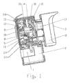
- Fig. 1 is an electrical switch 1 for a power tool with an electric motor, such as for an electric drill, a hammer drill, an electric screwdriver o. The like.
- the switch 1 has a housing 2 and an actuator 3, the user manually adjustable between an initial and an end position.
- the actuator 3 is in operative connection with a in Fig. 2 schematically shown signaling device 4 for generating a the adjustment of the actuator 3 associated signal.
- the actuator 3 is in the housing 2 and a contact system 5, 6, wherein the actuator 3 in each case a position, ie when reaching and / or leaving the respective movement position, switching on the respective contact system 5, 6 acts.
- the actuator 3 includes a pusher 16 as a handle for manual movement by the user, a leading plunger 17 in the housing 2 and a rigidly connected to the plunger 17 slider 18 in the housing 2, wherein the plunger 17 together with the slider 18 against the force of a return spring 19 is movable.
- the signaling device 4 is connected to a control device 7, which in Fig. 2 is shown as an integrated circuit for operating the power tool in conjunction.
- a control and / or regulation of the electric motor in the power tool such as its speed, torque o. The like.
- the control device 7 for controlling and / or regulating the rotational speed of a DC-operated electric motor with a pulse width modulation (PWM) control work. If it is an electric motor operated with alternating voltage, then the control device 7 for controlling and / or regulating the rotational speed of the electric motor can work with a phase angle control and / or a phase section control.
- PWM pulse width modulation
- the control device 7 is arranged on a printed circuit board 8, which is expediently located together with the control device 7 in the housing 2.
- the contact system 5 serves to switch on the power supply for the control device 7 and / or for the electric motor.
- the actuator 3 acts on the further contact system 5 when adjusting from the initial position switching by the contact system 5 is switched from the off in the on state.
- the contact system 5 is switched on by means of the control device 7 in dependence on the adjustment of the actuator 3 reduced voltage by pulse width modulation, phase control, phase section or the like. applied to the electric motor.
- the electric motor is thereby operated at a smaller than the maximum possible speed, wherein the size of the speed corresponds to the adjustment of the actuating member 3.
- the manual adjustment of the actuating member 3 by the user serves as a "gas" function for the electric motor.
- the contact system 6 is the bridging contact system for the control device 7, wherein the actuating member 3 acts in the end position switching on the contact system 6.
- the end position of the actuator 3 so that the previously located in the off state contact system 6 is turned on, in which case the full voltage applied to bridge the control device 7 on the electric motor, so that it runs at maximum speed.
- the contact system 6 is turned off when leaving the end position.
- the contact system 5 has a fixed contact 11 and a switching contact 9 in a largely conventional manner.
- the switching contact 9 of the further contact system 5 is designed as a pivotally mounted lever, as particularly in Fig. 2 you can see.
- a cam 22 on the plunger 17 of the actuator 3 acts on the one lever arm of the switch contact 9 in the starting position such that the switch contact 9 is removed in a first position from the fixed contact 11, whereby the contact system 5 is turned off.
- the actuator 3 Upon adjustment of the actuator 3 from the initial position of the cam 22 releases a lever arm, so that the other lever arm is applied by the action of the force of a spring 23 to the fixed contact 11.
- the switching contact 9 is applied to the fixed contact 11, thus the contact system 5 is turned on.
- the contact system 5 remains turned on until reaching the starting position and is then turned off in the starting position.
- the contact system 6 unlike in previous "Gasgebe" switches for power tools designed as a switch with a snap action jump contact system, as explained in more detail below.
- the contact system 6 also has a fixed contact 12, 13 and a switching contact 10.
- the switching contact 10 In a first position, the in Fig. 1 can be seen, the switching contact 10 is from Fixed contact 12, 13 removed, so that the contact system 6 is turned off. In a second position, which is not shown further, the switching contact 10 is located on the fixed contact 12, 13, whereby the contact system 6 is turned on.
- the switching contact 10 is mounted by means of a carriage 14 movable with respect to the actuator 3. Furthermore, the switching contact 10 is by means of an elastic element 15, namely a compression spring, with the actuating member 3 in operative connection by the compression spring 15 between the slider 18 and the carriage 14 is arranged.
- the compression spring 15 acts on the carriage 14 accordingly, upon movement of the actuator 3 into and / or out of the end position of the switch contact 10 with a kind of snap movement between the first and the second position of the contact system 6 switchable. In the end position of the actuator 3 so that a secure contact between the switch contact 10 and the fixed contacts 12, 13 is given even under difficult conditions and high loads. How to continue the Fig. 2 extracts, the switching contact 10 in the manner of a contact bridge for bridging the two fixed contacts 12, 13 configured, which further increases the contact reliability. Otherwise, in Fig. 1 and Fig. 2 the fixed contact 13, which is designed like the fixed contact 12, covered by a contact lug 24. The contact lug 24 serves for the electrical connection for the voltage supply of the components located on the printed circuit board 8, such as the control device 7.
- the signaling device 4 a slider 20.
- the grinder 20 is arranged on the actuating member 3, and more specifically on the plunger 17 and / or attached to the slider 18 and located within the housing 2.
- the grinder 20 cooperates with an at least one portion of the adjustment of the actuator 3 associated contact surface 21 electrically contacting together.
- the contact surface 21 is configured as a resistance surface in the manner of a potentiometer and is also located on the circuit board 8. Due to the electrical contact between the wiper 20 and the contact surface 21 is a signal corresponding to the adjustment of the actuator 3 generated, this signal as the setpoint of Control device 7 is supplied to the corresponding operation of the electric motor in response to the adjustment of the actuator 3.
Landscapes
- Rotary Switch, Piano Key Switch, And Lever Switch (AREA)
- Control Of Direct Current Motors (AREA)
Claims (7)
- Interrupteur électrique pour un outil électrique avec un moteur électrique, avec un organe d'actionnement (3) pouvant être réglé entre une position initiale et une position finale, avec un dispositif de signal (4) en liaison fonctionnelle avec l'organe d'actionnement (3) pour la génération d'un signal correspondant au trajet de réglage de l'organe d'actionnement (3), le dispositif de signal (4) interagissant avec un dispositif de commande (7) pour le fonctionnement du moteur électrique en fonction du trajet de réglage de l'organe d'actionnement (3) et avec un système de contact (6) servant de système de contact à pontage pour le dispositif de commande (7), l'organe d'actionnement (3) agissant, dans la position finale, sur le système de contact (6) de façon à ce que le système de contact (6) soit enclenché pour l'application de la tension entière au moteur électrique, caractérisé en ce que le système de contact (6) servant de système de contact à pontage est conçu comme système de contact à saut.
- Interrupteur électrique selon la revendication 1, caractérisé en ce que l'interrupteur (1) comprend un boîtier (2), en ce que de préférence le dispositif de commande (7) sert à la commande et/ou à la régulation du moteur électrique, comme son régime, son couple ou autre et en ce que de préférence le dispositif de commande (7) se trouve dans le boîtier (2).
- Interrupteur électrique selon la revendication 1 ou 2, caractérisé en ce que l'interrupteur (1) comprend un autre système de contact (5), en ce que de préférence l'organe d'actionnement (3) agit sur l'autre système de contact (5) lors du réglage à partir de la position initiale, plus particulièrement de façon à ce que le système de contact (5) soit enclenché pour l'alimentation en tension du dispositif de commande (7) et en ce que de préférence, à l'aide du dispositif de commande (7), lorsque le système de contact (5) est mis en marche, une tension réduite en fonction du trajet de réglage de l'organe d'actionnement (3) est appliquée au moteur électrique.
- Interrupteur électrique selon la revendication 1, 2 ou 3, caractérisé en ce que le système de contact (5, 6) comprend un contact fixe (11, 12, 13) ainsi qu'un contact de commutation (9, 10), le contact de commutation (9, 10) étant éloigné du contact fixe (11, 12, 13), dans une première position, de façon à ce que le système de contact (5, 6) soit désactivé et, dans une deuxième position, le contact de commutation (9, 10) s'appuie contre le contact fixe (11, 12, 13) de façon à ce que le système de contact (5, 6) soit activé.
- Interrupteur électrique selon l'une des revendications 1 à 4, caractérisé en ce que le contact de commutation (10) du système de contact (6) est logé, par exemple, à l'aide d'un chariot (14) mobile par rapport à l'organe d'actionnement (3), en ce que de préférence le contact de commutation (10) soit en liaison fonctionnelle, à l'aide d'un élément élastique (15), plus particulièrement d'un ressort de compression, avec l'organe d'actionnement (3), de façon à ce que, lors du mouvement de l'organe de fonctionnement (3) vers la et/ou à partir de la position finale, le contact de commutation (10), plus particulièrement, avec une sorte de mouvement d'encliquetage, puisse être commuté entre les deux positions et en ce que de préférence le contact de commutation (10) est conçu comme une sorte de pont de contact pour le pontage des deux contacts fixes (12, 13).
- Interrupteur électrique selon l'une des revendications 1 à 5, caractérisé en ce que le contact de commutation (9) de l'autre système de contact (5) est conçu comme un levier pivotant et en ce que de préférence une came (22) sur l'organe d'actionnement (3) libère, lors du réglage à partir de la position initiale, un bras de levier de façon à ce que l'autre bras de levier s'appuie contre le contact fixe (11) par l'action de la force d'un ressort (23).
- Interrupteur électrique selon l'une des revendications 1 à 6, caractérisé en ce que le dispositif de signal (4) comprend un curseur (20), disposé plus particulièrement sur l'organe d'actionnement (3), en ce que de préférence le curseur (20) interagit avec une surface de contact (21) correspondant à au moins une portion du trajet de réglage, plus particulièrement une surface de résistance conçue sous la forme d'une piste de potentiomètre et se trouvant, le cas échéant, sur un circuit imprimé, avec un contact électrique pour la génération du signal correspondant au trajet de réglage de l'organe d'actionnement (3) et en ce que de préférence le signal du dispositif de commande (7) est utilisé comme valeur de consigne pour le fonctionnement du moteur électrique en fonction du trajet de réglage de l'organe d'actionnement (3).
Applications Claiming Priority (2)
| Application Number | Priority Date | Filing Date | Title |
|---|---|---|---|
| DE102009005384 | 2009-01-21 | ||
| PCT/DE2010/000045 WO2010083808A1 (fr) | 2009-01-21 | 2010-01-19 | Commutateur électrique |
Publications (2)
| Publication Number | Publication Date |
|---|---|
| EP2380182A1 EP2380182A1 (fr) | 2011-10-26 |
| EP2380182B1 true EP2380182B1 (fr) | 2015-09-02 |
Family
ID=42124532
Family Applications (1)
| Application Number | Title | Priority Date | Filing Date |
|---|---|---|---|
| EP10706900.7A Active EP2380182B1 (fr) | 2009-01-21 | 2010-01-19 | Commutateur électrique |
Country Status (5)
| Country | Link |
|---|---|
| US (1) | US8410387B2 (fr) |
| EP (1) | EP2380182B1 (fr) |
| CN (1) | CN102388426B (fr) |
| DE (1) | DE102010004967A1 (fr) |
| WO (1) | WO2010083808A1 (fr) |
Families Citing this family (9)
| Publication number | Priority date | Publication date | Assignee | Title |
|---|---|---|---|---|
| DE102011017453A1 (de) * | 2010-04-21 | 2011-10-27 | Marquardt Verwaltungs-Gmbh | Elektrischer Schalter |
| CN102403155B (zh) * | 2010-09-08 | 2014-09-24 | 乐清市杰拉华电器有限公司 | 电动工具开关 |
| US10043619B2 (en) | 2014-03-28 | 2018-08-07 | Black & Decker Inc. | Biasing member for a power tool forward/reverse actuator |
| DE102014112982A1 (de) * | 2014-09-09 | 2016-03-10 | Johnson Electric Germany GmbH & Co. KG | Elektrischer Schalter |
| US10637379B2 (en) * | 2015-04-07 | 2020-04-28 | Black & Decker Inc. | Power tool with automatic feathering mode |
| DE102016117786A1 (de) * | 2016-09-21 | 2018-03-22 | Johnson Electric Germany GmbH & Co. KG | Elektrischer Schalter |
| US10541588B2 (en) | 2017-05-24 | 2020-01-21 | Black & Decker Inc. | Electronic power module for a power tool having an integrated heat sink |
| EP3588525B1 (fr) | 2018-06-28 | 2022-02-16 | Black & Decker Inc. | Module de commutateur électronique comportant des commutateurs de puissance agencés en vis-à-vis et des dissipateurs thermiques discrets |
| WO2020142894A1 (fr) * | 2019-01-08 | 2020-07-16 | 深圳拓邦股份有限公司 | Dispositif électronique, carte de circuit imprimé et outil électrique |
Family Cites Families (8)
| Publication number | Priority date | Publication date | Assignee | Title |
|---|---|---|---|---|
| US3142741A (en) * | 1962-07-11 | 1964-07-28 | Illinois Tool Works | Snap acting trigger switch |
| EP0886876B1 (fr) | 1996-03-15 | 2000-05-17 | Marquardt GmbH | Interrupteur electrique |
| DE19708939A1 (de) | 1996-03-15 | 1997-10-30 | Marquardt Gmbh | Elektrischer Schalter |
| DE19930558A1 (de) | 1998-07-24 | 2000-01-27 | Marquardt Gmbh | Elektrischer Schalter |
| US6736220B1 (en) * | 2003-05-22 | 2004-05-18 | Defond Components Limited | Power tool trigger assembly |
| DE102006061130B4 (de) * | 2006-01-09 | 2020-03-19 | Marquardt Gmbh | Elektrischer Schalter und Elektrowerkzeug mit einem solchen Schalter |
| WO2007090382A2 (fr) | 2006-02-10 | 2007-08-16 | Marquardt Gmbh | Commutateur électrique |
| DE102007005510B4 (de) | 2006-02-10 | 2019-09-26 | Marquardt Gmbh | Elektrischer Schalter und Elektrowerkzeug damit |
-
2010
- 2010-01-18 DE DE102010004967A patent/DE102010004967A1/de not_active Withdrawn
- 2010-01-19 CN CN201080013877.4A patent/CN102388426B/zh active Active
- 2010-01-19 EP EP10706900.7A patent/EP2380182B1/fr active Active
- 2010-01-19 WO PCT/DE2010/000045 patent/WO2010083808A1/fr not_active Ceased
-
2011
- 2011-07-19 US US13/185,839 patent/US8410387B2/en active Active
Also Published As
| Publication number | Publication date |
|---|---|
| DE102010004967A1 (de) | 2010-07-22 |
| EP2380182A1 (fr) | 2011-10-26 |
| US20120006662A1 (en) | 2012-01-12 |
| WO2010083808A1 (fr) | 2010-07-29 |
| CN102388426B (zh) | 2015-07-08 |
| US8410387B2 (en) | 2013-04-02 |
| CN102388426A (zh) | 2012-03-21 |
Similar Documents
| Publication | Publication Date | Title |
|---|---|---|
| WO2010083808A1 (fr) | Commutateur électrique | |
| DE60217613T3 (de) | Schaltgerät | |
| WO2021094152A1 (fr) | Procédé de commande et de régulation d'une machine-outil et poignée pour machine-outil | |
| DE112019004233T5 (de) | Auslöseschalter | |
| DE102007011658B4 (de) | Elektrischer Schalter | |
| EP0905850A2 (fr) | Pilotage d'un moteur électrique alimenté par secteur biphasé | |
| DE2629722A1 (de) | Handbetaetigbare einbauschaltvorrichtung | |
| EP1425770B1 (fr) | Dispositif de réglage et de commande pour appareils électriques | |
| EP2406801B1 (fr) | Interrupteur électrique | |
| EP2212979B1 (fr) | Outil électrique à main | |
| DE102010034377A1 (de) | Elektrischer Schalter | |
| EP1788597A1 (fr) | Outil à main électrique alimenté par batterie | |
| DE3324545A1 (de) | Elektromotorisch betriebenes handgeraet | |
| EP2561532B1 (fr) | Commutateur électrique | |
| DE102009009965A1 (de) | Elektrischer Schalter, insbesondere Elektrowerkzeugschalter | |
| DE102011009763B4 (de) | Elektrischer Schalter | |
| WO2009003703A2 (fr) | Dispositif de commande pour moteur électrique | |
| EP2110830A2 (fr) | Dispositif d'actionnement pour un outil manuel électrique doté d'un interrupteur d'inversion du sens de rotation | |
| DE2055859B2 (de) | Elektromotorisch angetriebene hand oder schlagbohrmaschine mit einstellbarer drehzahl | |
| DE102009004320B4 (de) | Elektrischer Schalter | |
| DE19510365A1 (de) | Stellglied, insbesondere für die Ansteuerung von Eletromotoren | |
| DE102006061130B4 (de) | Elektrischer Schalter und Elektrowerkzeug mit einem solchen Schalter | |
| DE3490794T1 (de) | Mikroschalter | |
| EP1971991B1 (fr) | Commutateur électrique | |
| DE202024105462U1 (de) | Elektrowerkzeug |
Legal Events
| Date | Code | Title | Description |
|---|---|---|---|
| PUAI | Public reference made under article 153(3) epc to a published international application that has entered the european phase |
Free format text: ORIGINAL CODE: 0009012 |
|
| 17P | Request for examination filed |
Effective date: 20110720 |
|
| AK | Designated contracting states |
Kind code of ref document: A1 Designated state(s): AT BE BG CH CY CZ DE DK EE ES FI FR GB GR HR HU IE IS IT LI LT LU LV MC MK MT NL NO PL PT RO SE SI SK SM TR |
|
| DAX | Request for extension of the european patent (deleted) | ||
| GRAP | Despatch of communication of intention to grant a patent |
Free format text: ORIGINAL CODE: EPIDOSNIGR1 |
|
| INTG | Intention to grant announced |
Effective date: 20150520 |
|
| GRAS | Grant fee paid |
Free format text: ORIGINAL CODE: EPIDOSNIGR3 |
|
| GRAA | (expected) grant |
Free format text: ORIGINAL CODE: 0009210 |
|
| AK | Designated contracting states |
Kind code of ref document: B1 Designated state(s): AT BE BG CH CY CZ DE DK EE ES FI FR GB GR HR HU IE IS IT LI LT LU LV MC MK MT NL NO PL PT RO SE SI SK SM TR |
|
| REG | Reference to a national code |
Ref country code: GB Ref legal event code: FG4D Free format text: NOT ENGLISH |
|
| REG | Reference to a national code |
Ref country code: AT Ref legal event code: REF Ref document number: 747078 Country of ref document: AT Kind code of ref document: T Effective date: 20150915 Ref country code: CH Ref legal event code: EP |
|
| REG | Reference to a national code |
Ref country code: IE Ref legal event code: FG4D Free format text: LANGUAGE OF EP DOCUMENT: GERMAN |
|
| REG | Reference to a national code |
Ref country code: DE Ref legal event code: R096 Ref document number: 502010010200 Country of ref document: DE |
|
| PG25 | Lapsed in a contracting state [announced via postgrant information from national office to epo] |
Ref country code: LT Free format text: LAPSE BECAUSE OF FAILURE TO SUBMIT A TRANSLATION OF THE DESCRIPTION OR TO PAY THE FEE WITHIN THE PRESCRIBED TIME-LIMIT Effective date: 20150902 Ref country code: GR Free format text: LAPSE BECAUSE OF FAILURE TO SUBMIT A TRANSLATION OF THE DESCRIPTION OR TO PAY THE FEE WITHIN THE PRESCRIBED TIME-LIMIT Effective date: 20151203 Ref country code: FI Free format text: LAPSE BECAUSE OF FAILURE TO SUBMIT A TRANSLATION OF THE DESCRIPTION OR TO PAY THE FEE WITHIN THE PRESCRIBED TIME-LIMIT Effective date: 20150902 Ref country code: NO Free format text: LAPSE BECAUSE OF FAILURE TO SUBMIT A TRANSLATION OF THE DESCRIPTION OR TO PAY THE FEE WITHIN THE PRESCRIBED TIME-LIMIT Effective date: 20151202 Ref country code: LV Free format text: LAPSE BECAUSE OF FAILURE TO SUBMIT A TRANSLATION OF THE DESCRIPTION OR TO PAY THE FEE WITHIN THE PRESCRIBED TIME-LIMIT Effective date: 20150902 |
|
| REG | Reference to a national code |
Ref country code: LT Ref legal event code: MG4D Ref country code: NL Ref legal event code: MP Effective date: 20150902 |
|
| PG25 | Lapsed in a contracting state [announced via postgrant information from national office to epo] |
Ref country code: HR Free format text: LAPSE BECAUSE OF FAILURE TO SUBMIT A TRANSLATION OF THE DESCRIPTION OR TO PAY THE FEE WITHIN THE PRESCRIBED TIME-LIMIT Effective date: 20150902 Ref country code: ES Free format text: LAPSE BECAUSE OF FAILURE TO SUBMIT A TRANSLATION OF THE DESCRIPTION OR TO PAY THE FEE WITHIN THE PRESCRIBED TIME-LIMIT Effective date: 20150902 Ref country code: SE Free format text: LAPSE BECAUSE OF FAILURE TO SUBMIT A TRANSLATION OF THE DESCRIPTION OR TO PAY THE FEE WITHIN THE PRESCRIBED TIME-LIMIT Effective date: 20150902 Ref country code: PL Free format text: LAPSE BECAUSE OF FAILURE TO SUBMIT A TRANSLATION OF THE DESCRIPTION OR TO PAY THE FEE WITHIN THE PRESCRIBED TIME-LIMIT Effective date: 20150902 |
|
| PG25 | Lapsed in a contracting state [announced via postgrant information from national office to epo] |
Ref country code: IT Free format text: LAPSE BECAUSE OF FAILURE TO SUBMIT A TRANSLATION OF THE DESCRIPTION OR TO PAY THE FEE WITHIN THE PRESCRIBED TIME-LIMIT Effective date: 20150902 Ref country code: NL Free format text: LAPSE BECAUSE OF FAILURE TO SUBMIT A TRANSLATION OF THE DESCRIPTION OR TO PAY THE FEE WITHIN THE PRESCRIBED TIME-LIMIT Effective date: 20150902 Ref country code: EE Free format text: LAPSE BECAUSE OF FAILURE TO SUBMIT A TRANSLATION OF THE DESCRIPTION OR TO PAY THE FEE WITHIN THE PRESCRIBED TIME-LIMIT Effective date: 20150902 Ref country code: CZ Free format text: LAPSE BECAUSE OF FAILURE TO SUBMIT A TRANSLATION OF THE DESCRIPTION OR TO PAY THE FEE WITHIN THE PRESCRIBED TIME-LIMIT Effective date: 20150902 Ref country code: IS Free format text: LAPSE BECAUSE OF FAILURE TO SUBMIT A TRANSLATION OF THE DESCRIPTION OR TO PAY THE FEE WITHIN THE PRESCRIBED TIME-LIMIT Effective date: 20160102 Ref country code: SK Free format text: LAPSE BECAUSE OF FAILURE TO SUBMIT A TRANSLATION OF THE DESCRIPTION OR TO PAY THE FEE WITHIN THE PRESCRIBED TIME-LIMIT Effective date: 20150902 |
|
| PG25 | Lapsed in a contracting state [announced via postgrant information from national office to epo] |
Ref country code: BE Free format text: LAPSE BECAUSE OF NON-PAYMENT OF DUE FEES Effective date: 20160131 Ref country code: RO Free format text: LAPSE BECAUSE OF FAILURE TO SUBMIT A TRANSLATION OF THE DESCRIPTION OR TO PAY THE FEE WITHIN THE PRESCRIBED TIME-LIMIT Effective date: 20150902 Ref country code: PT Free format text: LAPSE BECAUSE OF FAILURE TO SUBMIT A TRANSLATION OF THE DESCRIPTION OR TO PAY THE FEE WITHIN THE PRESCRIBED TIME-LIMIT Effective date: 20160104 |
|
| REG | Reference to a national code |
Ref country code: DE Ref legal event code: R097 Ref document number: 502010010200 Country of ref document: DE |
|
| PLBE | No opposition filed within time limit |
Free format text: ORIGINAL CODE: 0009261 |
|
| STAA | Information on the status of an ep patent application or granted ep patent |
Free format text: STATUS: NO OPPOSITION FILED WITHIN TIME LIMIT |
|
| 26N | No opposition filed |
Effective date: 20160603 |
|
| PG25 | Lapsed in a contracting state [announced via postgrant information from national office to epo] |
Ref country code: DK Free format text: LAPSE BECAUSE OF FAILURE TO SUBMIT A TRANSLATION OF THE DESCRIPTION OR TO PAY THE FEE WITHIN THE PRESCRIBED TIME-LIMIT Effective date: 20150902 Ref country code: SI Free format text: LAPSE BECAUSE OF FAILURE TO SUBMIT A TRANSLATION OF THE DESCRIPTION OR TO PAY THE FEE WITHIN THE PRESCRIBED TIME-LIMIT Effective date: 20150902 Ref country code: LU Free format text: LAPSE BECAUSE OF FAILURE TO SUBMIT A TRANSLATION OF THE DESCRIPTION OR TO PAY THE FEE WITHIN THE PRESCRIBED TIME-LIMIT Effective date: 20160119 |
|
| REG | Reference to a national code |
Ref country code: CH Ref legal event code: PL |
|
| GBPC | Gb: european patent ceased through non-payment of renewal fee |
Effective date: 20160119 |
|
| PG25 | Lapsed in a contracting state [announced via postgrant information from national office to epo] |
Ref country code: MC Free format text: LAPSE BECAUSE OF FAILURE TO SUBMIT A TRANSLATION OF THE DESCRIPTION OR TO PAY THE FEE WITHIN THE PRESCRIBED TIME-LIMIT Effective date: 20150902 |
|
| REG | Reference to a national code |
Ref country code: FR Ref legal event code: ST Effective date: 20160930 |
|
| PG25 | Lapsed in a contracting state [announced via postgrant information from national office to epo] |
Ref country code: CH Free format text: LAPSE BECAUSE OF NON-PAYMENT OF DUE FEES Effective date: 20160131 Ref country code: LI Free format text: LAPSE BECAUSE OF NON-PAYMENT OF DUE FEES Effective date: 20160131 Ref country code: GB Free format text: LAPSE BECAUSE OF NON-PAYMENT OF DUE FEES Effective date: 20160119 |
|
| REG | Reference to a national code |
Ref country code: IE Ref legal event code: MM4A |
|
| PG25 | Lapsed in a contracting state [announced via postgrant information from national office to epo] |
Ref country code: FR Free format text: LAPSE BECAUSE OF NON-PAYMENT OF DUE FEES Effective date: 20160201 |
|
| PG25 | Lapsed in a contracting state [announced via postgrant information from national office to epo] |
Ref country code: IE Free format text: LAPSE BECAUSE OF NON-PAYMENT OF DUE FEES Effective date: 20160119 |
|
| REG | Reference to a national code |
Ref country code: AT Ref legal event code: MM01 Ref document number: 747078 Country of ref document: AT Kind code of ref document: T Effective date: 20160119 |
|
| PG25 | Lapsed in a contracting state [announced via postgrant information from national office to epo] |
Ref country code: AT Free format text: LAPSE BECAUSE OF NON-PAYMENT OF DUE FEES Effective date: 20160119 |
|
| PG25 | Lapsed in a contracting state [announced via postgrant information from national office to epo] |
Ref country code: MT Free format text: LAPSE BECAUSE OF FAILURE TO SUBMIT A TRANSLATION OF THE DESCRIPTION OR TO PAY THE FEE WITHIN THE PRESCRIBED TIME-LIMIT Effective date: 20150902 |
|
| PG25 | Lapsed in a contracting state [announced via postgrant information from national office to epo] |
Ref country code: SM Free format text: LAPSE BECAUSE OF FAILURE TO SUBMIT A TRANSLATION OF THE DESCRIPTION OR TO PAY THE FEE WITHIN THE PRESCRIBED TIME-LIMIT Effective date: 20150902 Ref country code: HU Free format text: LAPSE BECAUSE OF FAILURE TO SUBMIT A TRANSLATION OF THE DESCRIPTION OR TO PAY THE FEE WITHIN THE PRESCRIBED TIME-LIMIT; INVALID AB INITIO Effective date: 20100119 Ref country code: CY Free format text: LAPSE BECAUSE OF FAILURE TO SUBMIT A TRANSLATION OF THE DESCRIPTION OR TO PAY THE FEE WITHIN THE PRESCRIBED TIME-LIMIT Effective date: 20150902 |
|
| PG25 | Lapsed in a contracting state [announced via postgrant information from national office to epo] |
Ref country code: MK Free format text: LAPSE BECAUSE OF FAILURE TO SUBMIT A TRANSLATION OF THE DESCRIPTION OR TO PAY THE FEE WITHIN THE PRESCRIBED TIME-LIMIT Effective date: 20150902 Ref country code: TR Free format text: LAPSE BECAUSE OF FAILURE TO SUBMIT A TRANSLATION OF THE DESCRIPTION OR TO PAY THE FEE WITHIN THE PRESCRIBED TIME-LIMIT Effective date: 20150902 |
|
| PG25 | Lapsed in a contracting state [announced via postgrant information from national office to epo] |
Ref country code: BG Free format text: LAPSE BECAUSE OF FAILURE TO SUBMIT A TRANSLATION OF THE DESCRIPTION OR TO PAY THE FEE WITHIN THE PRESCRIBED TIME-LIMIT Effective date: 20150902 |
|
| REG | Reference to a national code |
Ref country code: DE Ref legal event code: R082 Ref document number: 502010010200 Country of ref document: DE Representative=s name: PATENTANWAELTE STAEGER & SPERLING PARTNERSCHAF, DE Ref country code: DE Ref legal event code: R082 Ref document number: 502010010200 Country of ref document: DE Representative=s name: JOSTARNDT PATENTANWALTS-AG, DE |
|
| REG | Reference to a national code |
Ref country code: DE Ref legal event code: R082 Ref document number: 502010010200 Country of ref document: DE Representative=s name: PATENTANWAELTE STAEGER & SPERLING PARTNERSCHAF, DE Ref country code: DE Ref legal event code: R082 Ref document number: 502010010200 Country of ref document: DE |
|
| REG | Reference to a national code |
Ref country code: DE Ref legal event code: R082 Ref document number: 502010010200 Country of ref document: DE Representative=s name: PATENTANWAELTE STAEGER & SPERLING PARTNERSCHAF, DE |
|
| P01 | Opt-out of the competence of the unified patent court (upc) registered |
Effective date: 20230522 |
|
| PGFP | Annual fee paid to national office [announced via postgrant information from national office to epo] |
Ref country code: DE Payment date: 20260120 Year of fee payment: 17 |