EP2380295B1 - Feldkartierung mit integration zusätzlicher informationen - Google Patents
Feldkartierung mit integration zusätzlicher informationen Download PDFInfo
- Publication number
- EP2380295B1 EP2380295B1 EP10700283.4A EP10700283A EP2380295B1 EP 2380295 B1 EP2380295 B1 EP 2380295B1 EP 10700283 A EP10700283 A EP 10700283A EP 2380295 B1 EP2380295 B1 EP 2380295B1
- Authority
- EP
- European Patent Office
- Prior art keywords
- sync
- frame
- subfield
- time
- pattern
- Prior art date
- Legal status (The legal status is an assumption and is not a legal conclusion. Google has not performed a legal analysis and makes no representation as to the accuracy of the status listed.)
- Active
Links
Images


Classifications
-
- H—ELECTRICITY
- H04—ELECTRIC COMMUNICATION TECHNIQUE
- H04J—MULTIPLEX COMMUNICATION
- H04J3/00—Time-division multiplex systems
- H04J3/02—Details
- H04J3/06—Synchronising arrangements
- H04J3/0602—Systems characterised by the synchronising information used
- H04J3/0605—Special codes used as synchronising signal
-
- H—ELECTRICITY
- H04—ELECTRIC COMMUNICATION TECHNIQUE
- H04J—MULTIPLEX COMMUNICATION
- H04J3/00—Time-division multiplex systems
- H04J3/02—Details
- H04J3/06—Synchronising arrangements
- H04J3/0635—Clock or time synchronisation in a network
- H04J3/0638—Clock or time synchronisation among nodes; Internode synchronisation
- H04J3/0652—Synchronisation among time division multiple access [TDMA] nodes, e.g. time triggered protocol [TTP]
- H04J3/0655—Synchronisation among time division multiple access [TDMA] nodes, e.g. time triggered protocol [TTP] using timestamps
-
- H—ELECTRICITY
- H04—ELECTRIC COMMUNICATION TECHNIQUE
- H04Q—SELECTING
- H04Q11/00—Selecting arrangements for multiplex systems
- H04Q11/0001—Selecting arrangements for multiplex systems using optical switching
- H04Q11/0062—Network aspects
- H04Q11/0067—Provisions for optical access or distribution networks, e.g. Gigabit Ethernet Passive Optical Network (GE-PON), ATM-based Passive Optical Network (A-PON), PON-Ring
Definitions
- the present invention relates to communication technology, and more particular, to an apparatus and a method for implementing frame alignment in a passive optical network.
- frame alignment is the process of identifying a beginning and/or end of a transmitted bit stream, e.g. in a frame.
- Frame alignment may be needed to enable a receiver to synchronize an incoming bit stream in a frame and to extract the data in the frame for further processing.
- frame alignment is achieved using a distinctive bit sequence in the frame to distinguish the frame beginning and/or end and to locate the actual data in the frame.
- the bit sequence for frame alignment may also be referred to as a synchronization pattern or framing bits.
- the synchronization patterns used in communication systems are usually fixed bit sequences that are located at specified positions in the frame.
- the synchronization patterns can occur repeatedly in a sequence of frames or bit streams and do not carry additional information besides indicating the beginning and/or end of a frame. Improving such frame alignment schemes may improve frame processing efficiency in communication systems.
- DE 4015283 A1 discloses a method for synchronizing a system frame-structured in accordance with a digital synchronous hierarchy, particularly as specified in CCITT G.708.
- a hunt mode one frame sync word is detected, and then a first pointer (AU-4) is read which is spaced a predetermined distance from the sync word and addresses a cell-structured data area (VC4).
- AU-4 pointer
- VC4 cell-structured data area
- the headers of the ATM cells in the data area, which are addressed via the pointer are decoded, and if x successive correct cell headers are decoded, a transition to the sync state takes place.
- an incoming bit sequence is checked for a predetermined frame sync word (SDH frame) and then for code words representing regularly inserted cell headers, and a change to either a frame sync mode or a cell sync mode takes place.
- SDH frame predetermined frame sync word
- US 2003/007508 A1 discloses a system and method for management of bandwidth in a fiber optic, ethernet-based, TDMA communications system.
- a request/grant process is used to control the use of upstream bandwidth.
- a sense of time must therefore be shared by a headend and remote end-user devices.
- the invention provides for a gigabit media-independent interface in a media access controller to detect start-of-frame delimiters in incoming data. This allows for synchronization of a headend and end-user devices.
- the invention also allows for phase locking a transmit bit rate, at a headend, to the headend's clock. Transmitted data can the be used downstream to derive a local clock. Synchronization can also be maintained by the use of synchronization bytes in MPEG frames and/or variable length frames.
- the disclosure includes an apparatus for implementing frame alignment in a passive optical network, the apparatus comprising a frame alignment processor coupled to a receiver, wherein the frame alignment processor is configured to align a first frame and a second frame in the receiver by matching a first Synchronization (sync) pattern predicted using a first sync field in the first frame with a second sync pattern obtained from a second sync field in the second frame; and wherein the apparatus is configured to predict the first sync pattern based on the first time subfield and to obtain the second sync pattern from the second time subfield; wherein the first time subfield comprises first time information, the second time subfield comprises second time information; wherein the first sync field comprises a first sync subfield and a first time subfield, wherein the second sync field comprises a second sync subfield and a second time subfield, and wherein the first sync pattern is predicted based on the first time subfield and the second sync pattern is obtained from the second time subfield; wherein the first time subfield comprises first time information
- the disclosure includes a method for implementing frame alignment in a passive optical network, the method comprising receiving a first frame, subsequently receiving a second frame that was transmitted after the first frame, predicting a first sync pattern from a first sync field in the first frame, obtaining a second sync pattern from a second sync field in the second frame, and determining that the first frame and the second frame are aligned when the first sync pattern matches the second sync pattern; wherein the first sync field comprises a first sync subfield and a first time subfield, wherein the second sync field comprises a second sync subfield and a second time subfield; wherein the first time subfield comprises first time information, the second time subfield comprises second time information.
- an improved synchronization pattern for frame alignment may be inserted in a frame or bit stream.
- the improved synchronization pattern may indicate a beginning and/or end of the frame and additional information about the data in the frame.
- the additional information may be based on the data and hence may change in different frames that comprise different data.
- a synchronization state machine may be configured to predict a synchronization pattern in a next transported frame, e.g. with high or acceptable accuracy, using a synchronization pattern in at least one previously received frame.
- the frame alignment scheme may be used in different networks that may be based on different technologies or protocols, including PONs, Gigabit PON (GPON) systems, and Next Generation Access (NGA) systems.
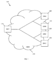
- FIG. 1 illustrates one embodiment of a PON 100, which may be one system for providing network access over "the last mile.”
- the PON 100 may be a point to multi-point network comprised of an optical line terminal (OLT) 110, a plurality of optical network units (ONUs) 120, and an optical distribution network (ODN) 130 that may be coupled to the OLT 110 and the ONUs 120.
- OLT optical line terminal
- ONUs optical network units
- ODN 130 optical distribution network
- the PON 100 may be a communications network that does not require any active components to distribute data between the OLT 110 and the ONUs 120. Instead, the PON 100 may use the passive optical components in the ODN 130 to distribute data between the OLT 110 and the ONUs 120.
- the PON 100 may be GPON system, where downstream data may be broadcasted at about 2.5 Gigabits per second (Gbps) and upstream data may be transmitted at about 1.25 Gbps.
- the PON 100 may be a NGA system, which may be configured to transport a plurality of data frames with improved reliability and efficiency at higher bandwidths.
- the PON 100 may be a ten Gbps GPONs (or XGPONs), which may have a downstream bandwidth of about ten Gbps and an upstream bandwidth of at least about 2.5 Gbps.
- suitable PONs 100 include the asynchronous transfer mode PON (APON) and the broadband PON (BPON) defined by the ITU-T G.983 standard, the GPON defined by the ITU-T G.984 standard, the Ethernet PON (EPON) defined by the IEEE 802.3ah standard, and the Wavelength Division Multiplexed (WDM) PON (WPON), all of which are incorporated herein by reference as if reproduced in their entirety.
- APON asynchronous transfer mode PON
- BPON broadband PON
- EPON Ethernet PON
- WDM Wavelength Division Multiplexed
- the OLT 110 may be any device that is configured to communicate with the ONUs 120 and another network (not shown). Specifically, the OLT 110 may act as an intermediary between the other network and the ONUs 120. For instance, the OLT 110 may forward data received from the network to the ONUs 120, and forward data received from the ONUs 120 onto the other network. Although the specific configuration of the OLT 110 may vary depending on the type of PON 100, in an embodiment, the OLT 110 may comprise a transmitter and a receiver.
- the OLT 110 may comprise a converter that converts the network protocol into the PON protocol.
- the OLT 110 converter may also convert the PON protocol into the network protocol.
- the OLT 110 may be typically located at a central location, such as a central office, but may be located at other locations as well.
- the ONUs 120 may be any devices that are configured to communicate with the OLT 110 and a customer or user (not shown). Specifically, the ONUs 120 may act as an intermediary between the OLT 110 and the customer. For instance, the ONUs 120 may forward data received from the OLT 110 to the customer, and forward data received from the customer onto the OLT 110. Although the specific configuration of the ONUs 120 may vary depending on the type of PON 100, in an embodiment, the ONUs 120 may comprise an optical transmitter configured to send optical signals to the OLT 110 and an optical receiver configured to receive optical signals from the OLT 110.
- the ONUs 120 may comprise a converter that converts the optical signal into electrical signals for the customer, such as signals in the Ethernet protocol, and a second transmitter and/or receiver that may send and/or receive the electrical signals to a customer device.
- ONUs 120 and optical network terminals (ONTs) are similar, and thus the terms are used interchangeably herein.
- the ONUs 120 may be typically located at distributed locations, such as the customer premises, but may be located at other locations as well.
- the ODN 130 may be a data distribution system, which may comprise optical fiber cables, couplers, splitters, distributors, and/or other equipment.
- the optical fiber cables, couplers, splitters, distributors, and/or other equipment may be passive optical components.
- the optical fiber cables, couplers, splitters, distributors, and/or other equipment may be components that do not require any power to distribute data signals between the OLT 110 and the ONUs 120.
- the ODN 130 may comprise one or a plurality of processing equipment, such as optical amplifiers.
- the ODN 130 may typically extend from the OLT 110 to the ONUs 120 in a branching configuration as shown in FIG. 1 , but may be alternatively configured in any other point-to-multi-point configuration.
- the OLT 110 and the ONUs 120 may exchange data that may be encapsulated in frames or packets, e.g. Ethernet frames.
- the frames may comprise payload and header, which may comprise synchronization and configuration information.
- a transmission convergence (TC) frame may be used to transmit information downstream, e.g. from the OLT 110 to an ONU 120, based a GPON Transmission Convergence (GTC) protocol layer.
- GTC GPON Transmission Convergence
- the GTC is defined in ITU-T G.984.3, which is incorporated herein by reference.
- the TC frame may also comprise a physical synchronization (PSync) field, which may indicate a beginning of the TC frame.
- PSync physical synchronization
- the PSync field may comprise a fixed code, which may have a fixed value of "0xB6AB31E0" (in hexadecimal format) that indicates the beginning of the frame.
- the size of such field may be equal to about four bytes.
- a receiver at the OLT 110 or ONU 120 may use the PSync fields in the received frames to delimit, e.g. separate and distinguish, the frames.
- the PSync field may be replaced with an improved synchronization pattern, which may be a modified PSync field.
- the modified PSync field may indicate the beginning (or end) of the frame and comprise other information.
- the additional information in the PSync field may further improve frame synchronization, e.g. at a receiver in the OLT 110 or the ONU 120.
- the additional information may be synchronization related information, such as timing information.
- the synchronization pattern may be processed by a synchronization state machine, which may be coupled to the receiver.
- the synchronization state machine may be implemented using hardware, software, or both.
- the synchronization state machine may obtain a plurality of synchronization patterns, which may comprise different but related synchronization information, and use this information to improve data synchronization and frame alignment. As such, the synchronization efficiency in the network may be enhanced and overall system performance may be improved.
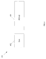
- FIG. 2 illustrates an embodiment of a PSync field 200, which may comprise delimiter information and additional synchronization information.
- the PSync field 200 may be inserted into a frame that comprises data before transmitting the frame, e.g. by a framer at an OLT or an ONU.
- the information the PSync field 200 may be extracted, e.g. by a receiver at the OLT or the ONU, to synchronize the frame with other received frames.
- the PSync field 200 comprises a synchronization (Sync) subfield 202 and a Time subfield 204.
- the Sync subfield 202 may indicate the beginning or end of the frame that comprises the PSync field 200.
- the Sync subfield 202 may comprise any known value or bit sequence that may be used to delimit a frame's beginning or end, such as used in Ethernet networks.
- the Time subfield 204 comprises time information, e.g. according to a Precision Time Protocol (PTP).
- PTP Precision Time Protocol
- the Time subfield 204 may comprise real time clock (RTC) information, which may be used by the receiver to process the frame or the data in the frame.
- RTC real time clock
- the information in the PSync field 200 may change in a plurality of transmitted frames.
- the synchronization pattern or bit sequence in the PSync field 200 may change as the RTC information in the Time subfield 204 changes in a sequence of transmitted frames.
- the synchronization pattern may be dependent on the RTC information, and hence a change in the synchronization pattern may be dependent on a change in the RTC information.
- the RTC information in a first received frame may be used to predict the synchronization pattern of a subsequent frame before receiving the next frame.
- the next received frame may then be aligned or locked properly after detecting an agreement or match between its synchronization pattern and the expected predicted synchronization pattern.
- the RTC information may indicate the transmission time of a frame, and each frame may be transmitted after a transmission delay of about 125 microseconds ( ⁇ s) from a previous frame.
- the transmission time of a first received frame may be obtained from the Time subfield 204, and then added to the transmission delay between frames (e.g. about 125 ⁇ s) to obtain an expected synchronization pattern of a second transmitted frame.
- the expected synchronization pattern may then be matched with an actual synchronization pattern in the second transmitted frame, which may be the Time subfield 204 of the second transmitted frame.
- the expected synchronization pattern may be used to lock or align a next received frame with substantially high accuracy, e.g. using a synchronization state machine.
- the length of the PSync field 200 may be equal to about 12 bytes
- the length of the Sync subfield 202 may be equal to about two bytes
- the length of the Time subfield 204 may be equal to about ten bytes.
- the length of the PSync field 200 may be increased in comparison to a typical length of about four bytes in current systems.
- the probability of having a mismatch between a properly predicted synchronization pattern of a frame and the actual synchronization pattern for that frame may be substantially small, e.g. equal to about 2 -96 per frame. Additionally, at this length, it may require a substantially long time to encounter a false match, e.g. equal to about 10 25 seconds, which may be longer than the lifetime of the universe.
- a mismatch in the synchronization pattern may indicate an error in the sequence of transmitted frames with a substantially high probability.
- errors in the frame header e.g. PSync field 200
- PSync field 200 may have substantially low occurrence or error rate, e.g. equal to about 10 -4 in about 100 frames. Such low error rate may be accounted for by a synchronization state machine.
- the Sync subfield 202 may be optional and the PSync field 200 may comprise the Time field 204.
- a synchronization pattern may be obtained based on the Time field 204.
- the synchronization pattern may be a CRC-16 pattern that may be computed using the Time field 204 information.
- Such scheme may also provide error detection and possibly error correction capability in the receiver.
- FIGS. 3 , 4 , 5 , 6 , and 7 illustrate other embodiments of PSync fields 300, 400, 500, 600, and 700, respectively, which may comprise delimiter information and additional synchronization information.
- the PSync fields 300, 400, 500, 600, and 700 may be inserted into a frame that comprises data before transmitting the frame, and may then be received and used to improve frame synchronization efficiency.
- the PSync fields 300, 400, 500, 600, and 700 may be used in GPONs and XG-PONs.
- the PSync field 300 may comprise a Sync subfield 302 and a Key Index subfield 304.
- the PSync field 400 may comprise a Sync subfield 402 and a PON ID subfield 404.
- the PSync field 500 may comprise a Sync subfield 502 and a Burst Profile Index subfield 504.
- the PSync field 600 may comprise a Sync subfield 602 and an OLT Transmitter Power subfield 604.
- the PSync field 700 may comprise a Sync subfield 702 and an OLT Version subfield 704.
- the Sync subfields 302, 402, 502, 602, and 702 may be configured and comprise information substantially similar to the Sync subfield 202.
- the Key Index subfield 304, the PON ID subfield 404, and the Burst Profile Index subfield 504 may comprise different non-trivial information related to the PON components and operations.
- the OLT Transmitter Power subfield 604 may comprise parameters related to the power of the OLT's transmitter.
- the OLT Version subfield 704 may comprise parameters related to the OLT version, including hardware major and minor versions, firmware major and minor versions, and supported link layer identifier (LLID) number.
- the lengths of the PSync fields 300, 400, 500, 600, and 700 and subfields contained therein may be different.
- the PSync fields 300, 400, 500, 600, and 700 may also comprise additional subfields that comprise non-trivial information (not shown).
- Other embodiments of the PSync fields 300, 400, 500, 600, and 700, which may comprise a plurality of subfields and have different lengths, may also be used in other networks.
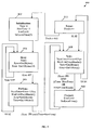
- FIG. 8 illustrates an embodiment of a synchronization state machine 800, which may be used to process a synchronization field, such as the PSync field 200, 300, 400, 500, 600, and 700, and align or lock a plurality of received frames.
- the synchronization state machine 800 may be used in a receiver in an OLT and/or ONU.
- the synchronization state machine 800 may comprise a plurality of states, including an Initialization state 802, a Hunt state 804, a Pre-Synchronization (PreSync) state 806, a Sync state 808, a Correct state 810, and an Error state 812.
- the synchronization state machine method 800 may be started at the Initialization state 802. During the Initialization state 802, a plurality of parameters may be initialized.
- a Time parameter that indicates a received frame time may be set to about zero.
- a NextTime parameter that indicates a received time of a next frame and a FrmErr parameter that indicates a count of encountered errors may each be set to about zero.
- a SetLocalTime() procedure may also be implemented, which may reset the receiver's local time to about zero. The synchronization state machine 800 may then proceed to the Hunt state 804.
- a Slip() procedure may be implemented, which may cause a framer, e.g. in the receiver, to slip or shift to a new bit position in a bit sequence of the received frame.
- a Get2Bytes() procedure may then be implemented to load about two bytes from the frame, e.g. starting from the new bit position. The two bytes may then be assigned to a Sync parameter.
- a Get10Bytes() procedure may be implemented to load about 10 bytes from the frame, e.g. after the previously loaded two bytes. The 10 bytes of data may then be assigned to the Time parameter.
- the data loaded in the Hunt state 804 may correspond to the information in a PSync field of the received frame, as shown above.
- the synchronization state machine 800 may then proceed to the PreSync state 806 if the obtained Sync parameter comprises a fixed pattern (FP), which may be known or standardized. Alternatively, the synchronization state machine 800 may return to the Hunt state 804 if the Sync parameter does not comprise the FP. Hence, a new Sync parameter and Time parameter may be loaded from the next bytes in the received frame.
- FP fixed pattern
- the PreSync state 806 the sum of the Time parameter value and a transmission delay between frames (e.g. 125 microseconds ( ⁇ s)) may be assigned to the NextTime parameter.
- the NextTime parameter may comprise a predicted arrival time for a next received frame.
- a WaitUntilNextHeader() procedure may then be implemented, which may cause the synchronization state machine 800 to wait until a next header is received in a next received frame.
- the Get2Bytes() and Get10Bytes procedures may be implemented in that sequence to load a new Sync parameter and a new Time parameter from the next frame or header.
- the synchronization state machine 800 may then proceed to the Sync state 808 if the obtained Sync parameter comprises the FP and if the Time parameter value is equal to about the NextTime parameter value. This condition may indicate that the synchronization information in the currently received frame may match to the expected or predicted synchronization information. Alternatively, the synchronization state machine 800 may return to the Hunt state 804 if the Sync parameter does not comprise the FP or if the Time parameter value is not equal to about the NextTime parameter value.
- the NextTime parameter may be updated to comprise the sum of the current Time parameter value and the transmission delay between frames (e.g. 125 ⁇ s).
- the WaitUntilNextHeader(), the Get2Bytes(), and the Get10Bytes procedures may be implemented in that sequence. If the currently obtained Sync parameter comprises the FP and if either: the Time parameter value is equal to about the NextTime parameter value or about the LocalTime parameter value, the synchronization information in the currently received frame may match the expected or predicted synchronization information. As such, the currently received frame may be locked or aligned properly, and the synchronization state machine 800 may then proceed to the Correct state 810. Alternatively, the synchronization state machine 800 may proceed to the Error state 808 if the condition above is not met.
- the FrmErr parameter that indicates the count of encountered errors may be reset to about zero, and the SetLocalTime() procedure may be implemented to reset the local time.
- the synchronization state machine 800 may then return to the Sync state 808 to resume the synchronization procedure of subsequent frames in the absence of detected errors.
- the FrmErr parameter may be incremented, e.g. by about one, to indicate that a matching error was encountered.
- the synchronization state machine 800 may then return to the Initialization state 802 if the FrmErr parameter value has exceeded about a maximum tolerated value M2, which may be equal to about eight or any other number. In this case, the frames may be considered in wrong alignment and the synchronization state machine 800 may be restarted to check the frame's alignment again. Alternatively, if the FrmErr parameter value has not exceeded the maximum tolerated value M2, the synchronization state machine 800 may return to the Sync state 808 to continue the synchronization procedure.
- relatively few isolated or random errors which may not be alignment errors, may not stop frame alignment. For example, some errors may be caused due to changes in local time and may not affect frame alignment in the long run.
- the real time clock will be modified (e.g. at the OLT) from time to time (e.g. leap seconds, etc.)
- other components e.g. the ONUs
- the Time will match the NextTime, and the local time on the ONU will be adjusted.
- FIG. 9 illustrates a typical, general-purpose network component 900 suitable for implementing one or more embodiments of the components disclosed herein.
- the network component 900 includes a processor 902 (which may be referred to as a central processor unit or CPU) that is in communication with memory devices including secondary storage 904, read only memory (ROM) 906, random access memory (RAM) 908, input/output (I/O) devices 910, and network connectivity devices 912.
- the processor 902 may be implemented as one or more CPU chips, or may be part of one or more application specific integrated circuits (ASICs).
- ASICs application specific integrated circuits
- the secondary storage 904 is typically comprised of one or more disk drives or tape drives and is used for non-volatile storage of data and as an over-flow data storage device if RAM 908 is not large enough to hold all working data. Secondary storage 904 may be used to store programs that are loaded into RAM 908 when such programs are selected for execution.
- the ROM 906 is used to store instructions and perhaps data that are read during program execution. ROM 906 is a non-volatile memory device that typically has a small memory capacity relative to the larger memory capacity of secondary storage 904.
- the RAM 908 is used to store volatile data and perhaps to store instructions. Access to both ROM 906 and RAM 908 is typically faster than to secondary storage 904.
- R R 1 + k * (R u - R 1 ), wherein k is a variable ranging from 1 percent to 100 percent with a 1 percent increment, i.e., k is 1 percent, 2 percent, 3 percent, 4 percent, 5 percent, ..., 50 percent, 51 percent, 52 percent, ..., 95 percent, 96 percent, 97 percent, 98 percent, 99 percent, or 100 percent.
- any numerical range defined by two R numbers as defined in the above is also specifically disclosed.
Landscapes
- Engineering & Computer Science (AREA)
- Computer Networks & Wireless Communication (AREA)
- Signal Processing (AREA)
- Synchronisation In Digital Transmission Systems (AREA)
- Small-Scale Networks (AREA)
Claims (13)
- Vorrichtung zur Realisierung einer Rahmenausrichtung in einem passiven optischen Netz (PON), umfassend: einen mit einem Empfänger gekoppelten Rahmenausrichtungsprozessor, wobei der Rahmenausrichtungsprozessor dazu konfiguriert ist, durch Abstimmen eines ersten Synchronisations- bzw. Sync-Musters, das mit einem ersten Sync-Feld (200) in dem ersten Rahmen vorhergesagt wird, mit einem zweiten Sync-Muster, das von einem zweiten Sync-Feld im zweiten Rahmen erhalten wird, einen ersten Rahmen und einen zweiten Rahmen in dem Empfänger auszurichten, wobei das erste Sync-Feld ein erstes Sync-Teilfeld (202) und ein erstes Zeitteilfeld (204) umfasst, wobei das zweite Sync-Feld ein zweites Sync-Teilfeld und ein zweites Zeitteilfeld umfasst, und wobei die Vorrichtung dazu konfiguriert ist, das erste Sync-Muster auf der Grundlage des ersten Zeitteilfelds (204) vorherzusagen und das zweite Sync-Muster aus dem zweiten Zeitteilfeld zu erhalten, wobei das erste Zeitteilfeld (204) erste Zeitinformationen umfasst und das zweite Zeitteilfeld zweite Zeitinformationen umfasst.
- Vorrichtung nach Anspruch 1, wobei das erste Sync-Feld (200) und das zweite Sync-Feld jeweils ein festgelegtes Muster umfassen, wobei das erste Zeitteilfeld (204) eine erste Zeit des Übertragens des ersten Rahmens umfasst und wobei das zweite Zeitteilfeld eine zweite Zeit des Übertragens des zweiten Rahmens umfasst.
- Vorrichtung nach Anspruch 2, wobei der Unterschied zwischen der ersten Zeit und der zweiten Zeit gleich ungefähr einer Übertragungsverzögerungszeit ist und wobei das vorhergesagte erste Sync-Muster gleich ungefähr der Summe der ersten Zeit und der Übertragungsverzögerungszeit ist.
- Vorrichtung nach Anspruch 1, wobei das erste Zeitteilfeld (204) Echtzeittaktinformationen umfasst, die von dem Empfänger zur Verarbeitung von Daten in dem ersten Rahmen verwendet werden.
- Vorrichtung nach Anspruch 1, wobei das erste Sync-Feld (200, 400) das erste Sync-Teilfeld (204, 402) und ein erstes Kennungsteilfeld (404) eines ersten passiven optischen Netzes, bzw. ein erstes PON-ID-Teilfeld, umfasst, und wobei das zweite Sync-Feld das zweite Sync-Teilfeld und ein zweites PON-ID-Teilfeld umfasst.
- Vorrichtung nach Anspruch 1, wobei das erste Sync-Feld (200, 700) das erste Sync-Teilfeld umfasst und ein Teilfeld (704) der Version eines optischen Leitungsendgeräts (OLT-Version, OLD - Optical Line Terminal) umfasst, wobei das OLT-Version-Teilfeld (704) mit der OLT-Version assoziierte Parameter umfasst, wobei die Parameter Hardware-"Major"- und -"Minor"-Versionen, Firmware-"Major"- und - "Minor"-Versionen und die Zahl der unterstützten Verbindungsschichtkennzeichnung bzw. LLID (Link Layer Identifier) umfasst.
- Vorrichtung nach Anspruch 1, wobei sich das erste Sync-Muster von dem zweiten Sync-Muster unterscheidet.
- Vorrichtung nach einem der Ansprüche 1-7, wobei die Vorrichtung ein optisches Leitungsendgerät, OLT (110), oder eine optische Netzwerkeinheit, ONU (Optical Network Unit) (120), in dem passiven optischen Netz ist.
- Verfahren zur Realisierung von Rahmenausrichtung in einem passiven optischen Netz (PON), umfassend:Empfangen eines ersten Rahmens;darauf Empfangen eines zweiten Rahmens, der nach dem ersten Rahmen übertragen wurde;Vorhersagen eines ersten Synchronisations- bzw. Sync-Musters von einem ersten Sync-Feld (200) im ersten Rahmen;Erhalten eines zweiten Sync-Musters von einem zweiten Sync-Feld in dem zweiten Rahmen undBestimmen, dass der erste Rahmen und der zweite Rahmen ausgerichtet sind, wenn das erste Sync-Muster mit dem zweiten Sync-Muster übereinstimmt;wobei das erste Sync-Feld (200) ein erstes Sync-Teilfeld (202) und ein erstes Zeitteilfeld (204) umfasst, wobei das zweite Sync-Feld ein zweites Sync-Teilfeld und ein zweites Zeitteilfeld umfasst; wobei das erste Zeitteilfeld (204) erste Zeitinformationen umfasst und das zweite Zeitteilfeld zweite Zeitinformationen umfasst.
- Verfahren nach Anspruch 9, wobei Vorhersagen des ersten Sync-Musters ein Hinzufügen einer ersten Übertragungszeit in dem ersten Sync-Feld (200) zu einer Übertragungsverzögerungszeit zwischen dem ersten Rahmen und dem zweiten Rahmen umfasst.
- Verfahren nach Anspruch 9, wobei das Verfahren ferner Detektieren des ersten Rahmens durch Detektieren eines festgelegten Musters in dem ersten Sync-Feld umfasst, wobei das Verfahren ferner Detektieren des zweiten Rahmens durch Detektieren des festgelegten Musters in dem zweiten Sync-Feld und Detektieren des vorhergesagten ersten Sync-Musters in dem zweiten Sync-Feld umfasst.
- Verfahren nach Anspruch 9, wobei der erste Rahmen und der zweite Rahmen ausgerichtet sind, falls der zweite Sync-Rahmen ein festgelegtes Muster und das vorhergesagte erste Sync-Muster oder eine lokale Zeit umfasst, und falls das erste Sync-Feld (200) das festgelegte Muster und ein vorhergesagtes zweites Sync-Muster von einem dritten Sync-Feld in einem dritten Rahmen, übertragen vor dem ersten Rahmen, umfasst.
- Passives optisches Netz, umfassend ein optisches Leitungsendgerät, OLT (110), mehrere optische Netzwerkeinheiten, ONUs (120), und ein optisches Verteilungsnetz, ODN (Optical Distribution Network) (130), gekoppelt mit dem OLT (110) und den ONUs (120), wobei das OLT (110) und/oder die ONU (120) eine Vorrichtung zur Realisierung von Rahmenausrichtung nach einem der Ansprüche 1-7 umfasst.
Priority Applications (1)
| Application Number | Priority Date | Filing Date | Title |
|---|---|---|---|
| EP16158619.3A EP3091676B1 (de) | 2009-01-06 | 2010-01-06 | Rahmensynchronisierung in einem pon |
Applications Claiming Priority (2)
| Application Number | Priority Date | Filing Date | Title |
|---|---|---|---|
| US14279709P | 2009-01-06 | 2009-01-06 | |
| PCT/US2010/020262 WO2010080837A1 (en) | 2009-01-06 | 2010-01-06 | Field framing with built-in information |
Related Child Applications (2)
| Application Number | Title | Priority Date | Filing Date |
|---|---|---|---|
| EP16158619.3A Division-Into EP3091676B1 (de) | 2009-01-06 | 2010-01-06 | Rahmensynchronisierung in einem pon |
| EP16158619.3A Division EP3091676B1 (de) | 2009-01-06 | 2010-01-06 | Rahmensynchronisierung in einem pon |
Publications (3)
| Publication Number | Publication Date |
|---|---|
| EP2380295A1 EP2380295A1 (de) | 2011-10-26 |
| EP2380295B1 true EP2380295B1 (de) | 2016-05-04 |
| EP2380295B8 EP2380295B8 (de) | 2016-08-10 |
Family
ID=42109969
Family Applications (2)
| Application Number | Title | Priority Date | Filing Date |
|---|---|---|---|
| EP10700283.4A Active EP2380295B8 (de) | 2009-01-06 | 2010-01-06 | Feldkartierung mit integration zusätzlicher informationen |
| EP16158619.3A Active EP3091676B1 (de) | 2009-01-06 | 2010-01-06 | Rahmensynchronisierung in einem pon |
Family Applications After (1)
| Application Number | Title | Priority Date | Filing Date |
|---|---|---|---|
| EP16158619.3A Active EP3091676B1 (de) | 2009-01-06 | 2010-01-06 | Rahmensynchronisierung in einem pon |
Country Status (5)
| Country | Link |
|---|---|
| US (2) | US8351787B2 (de) |
| EP (2) | EP2380295B8 (de) |
| CN (1) | CN102273109B (de) |
| ES (2) | ES2883407T3 (de) |
| WO (1) | WO2010080837A1 (de) |
Families Citing this family (15)
| Publication number | Priority date | Publication date | Assignee | Title |
|---|---|---|---|---|
| CN101795423A (zh) * | 2009-02-04 | 2010-08-04 | 中兴通讯股份有限公司 | 无源光网络系统的时间同步方法及其同步系统 |
| US8718482B1 (en) | 2009-11-10 | 2014-05-06 | Calix, Inc. | Transparent clock for precision timing distribution |
| US9225509B2 (en) * | 2010-11-02 | 2015-12-29 | Motorola Solutions, Inc. | Method and apparatus for achieving synchronization in a wireless communication system |
| US8977127B2 (en) * | 2012-08-15 | 2015-03-10 | Futurewei Technologies, Inc. | Inter-optical line terminal (OLT) communication in multiple-OLT passive optical networks (PONs) |
| US8855246B2 (en) | 2013-03-06 | 2014-10-07 | Qualcomm Incorporated | Demodulating a data packet based on a detected sync word |
| US9706481B2 (en) * | 2013-03-15 | 2017-07-11 | Futurewei Technologies, Inc. | System and method for time-power frequency hopping for D2D discovery |
| WO2015041057A1 (ja) * | 2013-09-20 | 2015-03-26 | セイコーインスツル株式会社 | 電子機器、通信システム及び電子機器の制御方法 |
| CN104660329B (zh) * | 2013-11-21 | 2019-12-13 | 上海诺基亚贝尔股份有限公司 | 一种在无源光网络中识别长发光流氓onu的方法 |
| US9654250B2 (en) | 2014-11-10 | 2017-05-16 | Futurewei Technologies, Inc. | Adding operations, administration, and maintenance (OAM) information in 66-bit code |
| US11153191B2 (en) * | 2018-01-19 | 2021-10-19 | Intel Corporation | Technologies for timestamping with error correction |
| EP3667951B1 (de) * | 2018-12-13 | 2022-06-29 | ADVA Optical Networking SE | Bestimmung der latenz einer optischen übertragungsverbindung |
| WO2020142726A1 (en) * | 2019-01-04 | 2020-07-09 | Futurewei Technologies, Inc. | Passive optical network (pon) synchronization and clock recovery |
| US11265096B2 (en) | 2019-05-13 | 2022-03-01 | Intel Corporation | High accuracy time stamping for multi-lane ports |
| CN112511914B (zh) * | 2020-01-22 | 2026-02-10 | 中兴通讯股份有限公司 | 状态切换方法、装置、设备和存储介质 |
| CN113709602B (zh) * | 2020-05-20 | 2022-09-09 | 华为技术有限公司 | 一种芯片同步方法及相关设备 |
Family Cites Families (14)
| Publication number | Priority date | Publication date | Assignee | Title |
|---|---|---|---|---|
| DE3832946A1 (de) | 1988-09-28 | 1990-04-05 | Siemens Ag | Verfahren zur verschluesselung digitaler zeitmultiplexsignale |
| DE4015283A1 (de) | 1990-05-12 | 1991-11-14 | Standard Elektrik Lorenz Ag | Verfahren und schaltungsanordnung zum erkennen unterschiedlicher datenstrukturen fuer asynchrone transport module uebertragende systeme |
| US5812335A (en) * | 1995-09-01 | 1998-09-22 | Adaptec, Inc. | Programmable data transfer without sector pulses in a headerless disk drive architecture |
| US20020171895A1 (en) | 2001-04-25 | 2002-11-21 | Glory Telecommunications Co., Ltd. | Automatic ranging in a passive optical network |
| WO2003005156A2 (en) | 2001-07-05 | 2003-01-16 | Broadcom Corporation | System, method, and computer program product for managing communications in ethernet-based fiber optic tdma networks |
| KR100421151B1 (ko) * | 2002-01-17 | 2004-03-04 | 삼성전자주식회사 | 기가비트 이더넷 수동 광 가입자 망 시스템에서의 동작구현방법 및 그 이더넷 프레임 구조 |
| US9337948B2 (en) | 2003-06-10 | 2016-05-10 | Alexander I. Soto | System and method for performing high-speed communications over fiber optical networks |
| US7349537B2 (en) | 2004-03-11 | 2008-03-25 | Teknovus, Inc. | Method for data encryption in an ethernet passive optical network |
| WO2006104630A1 (en) * | 2005-03-02 | 2006-10-05 | John Jamieson | An inverted passive optical network/inverted passive electrical network (ipon/ipen) based data fusion and synchronization system |
| JP4548324B2 (ja) * | 2005-12-02 | 2010-09-22 | 沖電気工業株式会社 | 1対n通信システム、同期確立方法及び同期追従方法 |
| CN100512059C (zh) | 2006-08-16 | 2009-07-08 | 华为技术有限公司 | 在无源光网络中传输同步数字体系业务的方法及装置 |
| US7991296B1 (en) * | 2006-11-10 | 2011-08-02 | Marvell International Ltd. | Method and apparatus for data frame synchronization and delineation |
| US7983308B1 (en) | 2006-11-28 | 2011-07-19 | Marvell International Ltd. | Method and apparatus for data frame synchronization |
| US8660146B2 (en) * | 2008-01-15 | 2014-02-25 | Telefonaktiebolaget Lm Ericsson (Publ) | Telecom multiplexer for variable rate composite bit stream |
-
2010
- 2010-01-06 US US12/683,330 patent/US8351787B2/en active Active
- 2010-01-06 EP EP10700283.4A patent/EP2380295B8/de active Active
- 2010-01-06 ES ES16158619T patent/ES2883407T3/es active Active
- 2010-01-06 EP EP16158619.3A patent/EP3091676B1/de active Active
- 2010-01-06 ES ES10700283.4T patent/ES2585579T3/es active Active
- 2010-01-06 CN CN201080003957.1A patent/CN102273109B/zh active Active
- 2010-01-06 WO PCT/US2010/020262 patent/WO2010080837A1/en not_active Ceased
-
2011
- 2011-12-22 US US13/335,593 patent/US8270832B2/en active Active
Also Published As
| Publication number | Publication date |
|---|---|
| WO2010080837A1 (en) | 2010-07-15 |
| ES2585579T3 (es) | 2016-10-06 |
| CN102273109A (zh) | 2011-12-07 |
| US20100172647A1 (en) | 2010-07-08 |
| CN102273109B (zh) | 2014-08-20 |
| US8351787B2 (en) | 2013-01-08 |
| EP2380295B8 (de) | 2016-08-10 |
| EP3091676A1 (de) | 2016-11-09 |
| ES2883407T3 (es) | 2021-12-07 |
| EP2380295A1 (de) | 2011-10-26 |
| US20120093513A1 (en) | 2012-04-19 |
| EP3091676B1 (de) | 2021-05-26 |
| US8270832B2 (en) | 2012-09-18 |
Similar Documents
| Publication | Publication Date | Title |
|---|---|---|
| EP2380295B1 (de) | Feldkartierung mit integration zusätzlicher informationen | |
| EP2955868B1 (de) | Durch header-fehler-steuerung geschützte abwärtsrahmensynchronisationsmuster eines passiven optischen 10-gigabit-netzwerks | |
| EP2784963B1 (de) | Verfahren zum Einrahmen von Daten und Vorrichtung dafür | |
| US7991296B1 (en) | Method and apparatus for data frame synchronization and delineation | |
| RU2558385C2 (ru) | Индикация длины волны в пассивных оптических сетях с множеством длин волн |
Legal Events
| Date | Code | Title | Description |
|---|---|---|---|
| PUAI | Public reference made under article 153(3) epc to a published international application that has entered the european phase |
Free format text: ORIGINAL CODE: 0009012 |
|
| 17P | Request for examination filed |
Effective date: 20110718 |
|
| AK | Designated contracting states |
Kind code of ref document: A1 Designated state(s): AT BE BG CH CY CZ DE DK EE ES FI FR GB GR HR HU IE IS IT LI LT LU LV MC MK MT NL NO PL PT RO SE SI SK SM TR |
|
| DAX | Request for extension of the european patent (deleted) | ||
| 17Q | First examination report despatched |
Effective date: 20130305 |
|
| GRAP | Despatch of communication of intention to grant a patent |
Free format text: ORIGINAL CODE: EPIDOSNIGR1 |
|
| INTG | Intention to grant announced |
Effective date: 20151109 |
|
| GRAS | Grant fee paid |
Free format text: ORIGINAL CODE: EPIDOSNIGR3 |
|
| GRAA | (expected) grant |
Free format text: ORIGINAL CODE: 0009210 |
|
| AK | Designated contracting states |
Kind code of ref document: B1 Designated state(s): AT BE BG CH CY CZ DE DK EE ES FI FR GB GR HR HU IE IS IT LI LT LU LV MC MK MT NL NO PL PT RO SE SI SK SM TR |
|
| REG | Reference to a national code |
Ref country code: GB Ref legal event code: FG4D |
|
| REG | Reference to a national code |
Ref country code: CH Ref legal event code: EP |
|
| REG | Reference to a national code |
Ref country code: AT Ref legal event code: REF Ref document number: 797717 Country of ref document: AT Kind code of ref document: T Effective date: 20160515 |
|
| GRAT | Correction requested after decision to grant or after decision to maintain patent in amended form |
Free format text: ORIGINAL CODE: EPIDOSNCDEC |
|
| RIN2 | Information on inventor provided after grant (corrected) |
Inventor name: LUO, YUANQIU Inventor name: EFFENBERGER, FRANK J. |
|
| REG | Reference to a national code |
Ref country code: IE Ref legal event code: FG4D |
|
| REG | Reference to a national code |
Ref country code: DE Ref legal event code: R096 Ref document number: 602010033017 Country of ref document: DE |
|
| RAP2 | Party data changed (patent owner data changed or rights of a patent transferred) |
Owner name: HUAWEI TECHNOLOGIES CO., LTD. |
|
| REG | Reference to a national code |
Ref country code: NL Ref legal event code: FP |
|
| REG | Reference to a national code |
Ref country code: LT Ref legal event code: MG4D |
|
| REG | Reference to a national code |
Ref country code: ES Ref legal event code: FG2A Ref document number: 2585579 Country of ref document: ES Kind code of ref document: T3 Effective date: 20161006 |
|
| PG25 | Lapsed in a contracting state [announced via postgrant information from national office to epo] |
Ref country code: FI Free format text: LAPSE BECAUSE OF FAILURE TO SUBMIT A TRANSLATION OF THE DESCRIPTION OR TO PAY THE FEE WITHIN THE PRESCRIBED TIME-LIMIT Effective date: 20160504 Ref country code: NO Free format text: LAPSE BECAUSE OF FAILURE TO SUBMIT A TRANSLATION OF THE DESCRIPTION OR TO PAY THE FEE WITHIN THE PRESCRIBED TIME-LIMIT Effective date: 20160804 Ref country code: LT Free format text: LAPSE BECAUSE OF FAILURE TO SUBMIT A TRANSLATION OF THE DESCRIPTION OR TO PAY THE FEE WITHIN THE PRESCRIBED TIME-LIMIT Effective date: 20160504 |
|
| REG | Reference to a national code |
Ref country code: AT Ref legal event code: MK05 Ref document number: 797717 Country of ref document: AT Kind code of ref document: T Effective date: 20160504 |
|
| PG25 | Lapsed in a contracting state [announced via postgrant information from national office to epo] |
Ref country code: LV Free format text: LAPSE BECAUSE OF FAILURE TO SUBMIT A TRANSLATION OF THE DESCRIPTION OR TO PAY THE FEE WITHIN THE PRESCRIBED TIME-LIMIT Effective date: 20160504 Ref country code: PT Free format text: LAPSE BECAUSE OF FAILURE TO SUBMIT A TRANSLATION OF THE DESCRIPTION OR TO PAY THE FEE WITHIN THE PRESCRIBED TIME-LIMIT Effective date: 20160905 Ref country code: GR Free format text: LAPSE BECAUSE OF FAILURE TO SUBMIT A TRANSLATION OF THE DESCRIPTION OR TO PAY THE FEE WITHIN THE PRESCRIBED TIME-LIMIT Effective date: 20160805 Ref country code: HR Free format text: LAPSE BECAUSE OF FAILURE TO SUBMIT A TRANSLATION OF THE DESCRIPTION OR TO PAY THE FEE WITHIN THE PRESCRIBED TIME-LIMIT Effective date: 20160504 Ref country code: SE Free format text: LAPSE BECAUSE OF FAILURE TO SUBMIT A TRANSLATION OF THE DESCRIPTION OR TO PAY THE FEE WITHIN THE PRESCRIBED TIME-LIMIT Effective date: 20160504 |
|
| REG | Reference to a national code |
Ref country code: FR Ref legal event code: PLFP Year of fee payment: 8 |
|
| PG25 | Lapsed in a contracting state [announced via postgrant information from national office to epo] |
Ref country code: EE Free format text: LAPSE BECAUSE OF FAILURE TO SUBMIT A TRANSLATION OF THE DESCRIPTION OR TO PAY THE FEE WITHIN THE PRESCRIBED TIME-LIMIT Effective date: 20160504 Ref country code: RO Free format text: LAPSE BECAUSE OF FAILURE TO SUBMIT A TRANSLATION OF THE DESCRIPTION OR TO PAY THE FEE WITHIN THE PRESCRIBED TIME-LIMIT Effective date: 20160504 Ref country code: CZ Free format text: LAPSE BECAUSE OF FAILURE TO SUBMIT A TRANSLATION OF THE DESCRIPTION OR TO PAY THE FEE WITHIN THE PRESCRIBED TIME-LIMIT Effective date: 20160504 Ref country code: SK Free format text: LAPSE BECAUSE OF FAILURE TO SUBMIT A TRANSLATION OF THE DESCRIPTION OR TO PAY THE FEE WITHIN THE PRESCRIBED TIME-LIMIT Effective date: 20160504 Ref country code: DK Free format text: LAPSE BECAUSE OF FAILURE TO SUBMIT A TRANSLATION OF THE DESCRIPTION OR TO PAY THE FEE WITHIN THE PRESCRIBED TIME-LIMIT Effective date: 20160504 |
|
| REG | Reference to a national code |
Ref country code: DE Ref legal event code: R097 Ref document number: 602010033017 Country of ref document: DE |
|
| PG25 | Lapsed in a contracting state [announced via postgrant information from national office to epo] |
Ref country code: AT Free format text: LAPSE BECAUSE OF FAILURE TO SUBMIT A TRANSLATION OF THE DESCRIPTION OR TO PAY THE FEE WITHIN THE PRESCRIBED TIME-LIMIT Effective date: 20160504 Ref country code: SM Free format text: LAPSE BECAUSE OF FAILURE TO SUBMIT A TRANSLATION OF THE DESCRIPTION OR TO PAY THE FEE WITHIN THE PRESCRIBED TIME-LIMIT Effective date: 20160504 Ref country code: BE Free format text: LAPSE BECAUSE OF FAILURE TO SUBMIT A TRANSLATION OF THE DESCRIPTION OR TO PAY THE FEE WITHIN THE PRESCRIBED TIME-LIMIT Effective date: 20160504 Ref country code: PL Free format text: LAPSE BECAUSE OF FAILURE TO SUBMIT A TRANSLATION OF THE DESCRIPTION OR TO PAY THE FEE WITHIN THE PRESCRIBED TIME-LIMIT Effective date: 20160504 |
|
| PLBE | No opposition filed within time limit |
Free format text: ORIGINAL CODE: 0009261 |
|
| STAA | Information on the status of an ep patent application or granted ep patent |
Free format text: STATUS: NO OPPOSITION FILED WITHIN TIME LIMIT |
|
| 26N | No opposition filed |
Effective date: 20170207 |
|
| REG | Reference to a national code |
Ref country code: DE Ref legal event code: R081 Ref document number: 602010033017 Country of ref document: DE Owner name: HUAWEI TECHNOLOGIES CO., LTD., SHENZHEN, CN Free format text: FORMER OWNERS: EFFENBERGER, FRANK J., FREEHOLD, N.J., US; HUAWEI TECHNOLOGIES CO., LTD., SHENZHEN, GUANGDONG, CN; LUO, YUANQIU, CRANBURY, N.J., US Ref country code: DE Ref legal event code: R081 Ref document number: 602010033017 Country of ref document: DE Owner name: HUAWEI TECHNOLOGIES CO., LTD., SHENZHEN, CN Free format text: FORMER OWNERS: EFFENBERGER, FRANK J., FREEHOLD, N.J., US; HUAWEI TECHNOLOGIES CO., LTD., SHENZHEN, GUANGDONG PROVINCE, CN; LUO, YUANQIU, CRANBURY, N.J., US |
|
| PG25 | Lapsed in a contracting state [announced via postgrant information from national office to epo] |
Ref country code: SI Free format text: LAPSE BECAUSE OF FAILURE TO SUBMIT A TRANSLATION OF THE DESCRIPTION OR TO PAY THE FEE WITHIN THE PRESCRIBED TIME-LIMIT Effective date: 20160504 |
|
| REG | Reference to a national code |
Ref country code: CH Ref legal event code: PL |
|
| PG25 | Lapsed in a contracting state [announced via postgrant information from national office to epo] |
Ref country code: MC Free format text: LAPSE BECAUSE OF FAILURE TO SUBMIT A TRANSLATION OF THE DESCRIPTION OR TO PAY THE FEE WITHIN THE PRESCRIBED TIME-LIMIT Effective date: 20160504 |
|
| PG25 | Lapsed in a contracting state [announced via postgrant information from national office to epo] |
Ref country code: LI Free format text: LAPSE BECAUSE OF NON-PAYMENT OF DUE FEES Effective date: 20170131 Ref country code: CH Free format text: LAPSE BECAUSE OF NON-PAYMENT OF DUE FEES Effective date: 20170131 |
|
| REG | Reference to a national code |
Ref country code: IE Ref legal event code: MM4A |
|
| PG25 | Lapsed in a contracting state [announced via postgrant information from national office to epo] |
Ref country code: LU Free format text: LAPSE BECAUSE OF NON-PAYMENT OF DUE FEES Effective date: 20170106 |
|
| REG | Reference to a national code |
Ref country code: FR Ref legal event code: PLFP Year of fee payment: 9 |
|
| PG25 | Lapsed in a contracting state [announced via postgrant information from national office to epo] |
Ref country code: IE Free format text: LAPSE BECAUSE OF NON-PAYMENT OF DUE FEES Effective date: 20170106 |
|
| PG25 | Lapsed in a contracting state [announced via postgrant information from national office to epo] |
Ref country code: MT Free format text: LAPSE BECAUSE OF NON-PAYMENT OF DUE FEES Effective date: 20170106 |
|
| PG25 | Lapsed in a contracting state [announced via postgrant information from national office to epo] |
Ref country code: HU Free format text: LAPSE BECAUSE OF FAILURE TO SUBMIT A TRANSLATION OF THE DESCRIPTION OR TO PAY THE FEE WITHIN THE PRESCRIBED TIME-LIMIT; INVALID AB INITIO Effective date: 20100106 |
|
| PG25 | Lapsed in a contracting state [announced via postgrant information from national office to epo] |
Ref country code: BG Free format text: LAPSE BECAUSE OF FAILURE TO SUBMIT A TRANSLATION OF THE DESCRIPTION OR TO PAY THE FEE WITHIN THE PRESCRIBED TIME-LIMIT Effective date: 20160504 |
|
| PG25 | Lapsed in a contracting state [announced via postgrant information from national office to epo] |
Ref country code: CY Free format text: LAPSE BECAUSE OF NON-PAYMENT OF DUE FEES Effective date: 20160504 |
|
| PG25 | Lapsed in a contracting state [announced via postgrant information from national office to epo] |
Ref country code: MK Free format text: LAPSE BECAUSE OF FAILURE TO SUBMIT A TRANSLATION OF THE DESCRIPTION OR TO PAY THE FEE WITHIN THE PRESCRIBED TIME-LIMIT Effective date: 20160504 |
|
| PG25 | Lapsed in a contracting state [announced via postgrant information from national office to epo] |
Ref country code: IS Free format text: LAPSE BECAUSE OF FAILURE TO SUBMIT A TRANSLATION OF THE DESCRIPTION OR TO PAY THE FEE WITHIN THE PRESCRIBED TIME-LIMIT Effective date: 20160904 |
|
| P01 | Opt-out of the competence of the unified patent court (upc) registered |
Effective date: 20230524 |
|
| PGFP | Annual fee paid to national office [announced via postgrant information from national office to epo] |
Ref country code: GB Payment date: 20251204 Year of fee payment: 17 |
|
| PGFP | Annual fee paid to national office [announced via postgrant information from national office to epo] |
Ref country code: NL Payment date: 20251215 Year of fee payment: 17 Ref country code: FR Payment date: 20251208 Year of fee payment: 17 |
|
| PGFP | Annual fee paid to national office [announced via postgrant information from national office to epo] |
Ref country code: ES Payment date: 20260209 Year of fee payment: 17 |
|
| PGFP | Annual fee paid to national office [announced via postgrant information from national office to epo] |
Ref country code: DE Payment date: 20251203 Year of fee payment: 17 |
|
| PGFP | Annual fee paid to national office [announced via postgrant information from national office to epo] |
Ref country code: IT Payment date: 20251219 Year of fee payment: 17 |
|
| PGFP | Annual fee paid to national office [announced via postgrant information from national office to epo] |
Ref country code: TR Payment date: 20260105 Year of fee payment: 17 |