EP2380399B1 - Table de cuisson comprenant plusieurs éléments chauffants et au moins un module d'électronique de puissance - Google Patents
Table de cuisson comprenant plusieurs éléments chauffants et au moins un module d'électronique de puissance Download PDFInfo
- Publication number
- EP2380399B1 EP2380399B1 EP20090774881 EP09774881A EP2380399B1 EP 2380399 B1 EP2380399 B1 EP 2380399B1 EP 20090774881 EP20090774881 EP 20090774881 EP 09774881 A EP09774881 A EP 09774881A EP 2380399 B1 EP2380399 B1 EP 2380399B1
- Authority
- EP
- European Patent Office
- Prior art keywords
- switching arrangement
- subassembly
- heating elements
- power electronics
- heating
- Prior art date
- Legal status (The legal status is an assumption and is not a legal conclusion. Google has not performed a legal analysis and makes no representation as to the accuracy of the status listed.)
- Active
Links
Images


Classifications
-
- H—ELECTRICITY
- H05—ELECTRIC TECHNIQUES NOT OTHERWISE PROVIDED FOR
- H05B—ELECTRIC HEATING; ELECTRIC LIGHT SOURCES NOT OTHERWISE PROVIDED FOR; CIRCUIT ARRANGEMENTS FOR ELECTRIC LIGHT SOURCES, IN GENERAL
- H05B6/00—Heating by electric, magnetic or electromagnetic fields
- H05B6/02—Induction heating
- H05B6/06—Control, e.g. of temperature, of power
-
- H—ELECTRICITY
- H05—ELECTRIC TECHNIQUES NOT OTHERWISE PROVIDED FOR
- H05B—ELECTRIC HEATING; ELECTRIC LIGHT SOURCES NOT OTHERWISE PROVIDED FOR; CIRCUIT ARRANGEMENTS FOR ELECTRIC LIGHT SOURCES, IN GENERAL
- H05B6/00—Heating by electric, magnetic or electromagnetic fields
- H05B6/02—Induction heating
- H05B6/10—Induction heating apparatus, other than furnaces, for specific applications
- H05B6/12—Cooking devices
- H05B6/1209—Cooking devices induction cooking plates or the like and devices to be used in combination with them
-
- H—ELECTRICITY
- H05—ELECTRIC TECHNIQUES NOT OTHERWISE PROVIDED FOR
- H05B—ELECTRIC HEATING; ELECTRIC LIGHT SOURCES NOT OTHERWISE PROVIDED FOR; CIRCUIT ARRANGEMENTS FOR ELECTRIC LIGHT SOURCES, IN GENERAL
- H05B6/00—Heating by electric, magnetic or electromagnetic fields
- H05B6/02—Induction heating
- H05B6/06—Control, e.g. of temperature, of power
- H05B6/062—Control, e.g. of temperature, of power for cooking plates or the like
- H05B6/065—Control, e.g. of temperature, of power for cooking plates or the like using coordinated control of multiple induction coils
-
- H—ELECTRICITY
- H05—ELECTRIC TECHNIQUES NOT OTHERWISE PROVIDED FOR
- H05B—ELECTRIC HEATING; ELECTRIC LIGHT SOURCES NOT OTHERWISE PROVIDED FOR; CIRCUIT ARRANGEMENTS FOR ELECTRIC LIGHT SOURCES, IN GENERAL
- H05B6/00—Heating by electric, magnetic or electromagnetic fields
- H05B6/02—Induction heating
- H05B6/10—Induction heating apparatus, other than furnaces, for specific applications
- H05B6/12—Cooking devices
-
- H—ELECTRICITY
- H05—ELECTRIC TECHNIQUES NOT OTHERWISE PROVIDED FOR
- H05B—ELECTRIC HEATING; ELECTRIC LIGHT SOURCES NOT OTHERWISE PROVIDED FOR; CIRCUIT ARRANGEMENTS FOR ELECTRIC LIGHT SOURCES, IN GENERAL
- H05B2213/00—Aspects relating both to resistive heating and to induction heating, covered by H05B3/00 and H05B6/00
- H05B2213/03—Heating plates made out of a matrix of heating elements that can define heating areas adapted to cookware randomly placed on the heating plate
-
- Y—GENERAL TAGGING OF NEW TECHNOLOGICAL DEVELOPMENTS; GENERAL TAGGING OF CROSS-SECTIONAL TECHNOLOGIES SPANNING OVER SEVERAL SECTIONS OF THE IPC; TECHNICAL SUBJECTS COVERED BY FORMER USPC CROSS-REFERENCE ART COLLECTIONS [XRACs] AND DIGESTS
- Y02—TECHNOLOGIES OR APPLICATIONS FOR MITIGATION OR ADAPTATION AGAINST CLIMATE CHANGE
- Y02B—CLIMATE CHANGE MITIGATION TECHNOLOGIES RELATED TO BUILDINGS, e.g. HOUSING, HOUSE APPLIANCES OR RELATED END-USER APPLICATIONS
- Y02B40/00—Technologies aiming at improving the efficiency of home appliances, e.g. induction cooking or efficient technologies for refrigerators, freezers or dish washers
Definitions
- the invention relates to a hob with a plurality of heating elements and at least one power electronics module according to the preamble of claim 1.
- an induction hob having a plurality of heating elements, two power electronics assemblies for generating a heating current for operating the heating elements and a switching arrangement for establishing and disconnecting a connection between the power electronics module and the heating elements is known.
- the switching arrangement is mounted in a generic hobs with the inverters, which form the power electronics module on a circuit board.
- simpler cooktops are known in which the heating elements are permanently wired, each with a power electronics module without intervening switching arrangement.
- an induction hob with a plurality of heating elements and at least one power electronics module for generating a heating current for operating the heating elements is known.
- a switching arrangement for establishing and disconnecting a connection between the power electronics module and the heating elements is provided.
- the invention is in particular the object of providing a hob with a flexible architecture.
- the invention relates to a hob, in particular an induction hob, with a plurality of heating elements, at least one power electronics module for generating a heating current for operating the heating elements and with a switching arrangement for establishing and disconnecting a connection between the power electronics module and the heating elements.
- the switching arrangement is designed as an assembly separate from the power electronics module.
- the same power electronics assembly can be used both in cooktops having heating elements hardwired to the power electronics assembly and in cooktops including circuitry for establishing and disconnecting the connection between the heating element and the power electronics assembly.
- An adaptation of the switching arrangement and the power electronics module to different operating conditions can be done independently, so that, for example, the power electronics module for different countries with different household power networks can be chosen differently. Even when servicing an exchange of a single module can be made possible cost.
- the advantages of the invention are particularly evident in induction cooking fields, in which the heating elements are inductors and in which the power electronics module comprises at least one inverter for generating the heating current.
- the power electronics module comprises at least two inverters. Increasing the number of inverters and / or inductors increases the complexity of the circuit arrangement, so that the provision of a separate module with increasing inductor number becomes more and more expedient.
- the switching arrangement comprises a plurality of capacitors, which are each assigned to a heating element designed as an inductor. Since the switching arrangement usually already comprises one output per inductor, the resonant capacitor, which complements the inductor to a resonant resonant circuit, can be very well integrated into the switching arrangement.
- the assembly of the switch assembly includes a pot detection circuit, it may be protected from interference from the power electronics assembly or inverters, and the outputs to the inductors may be used to transmit sensing pulses to the inductors.
- the assembly of the switching arrangement comprises a microcontroller for actuating switching elements of the switching arrangement. This allows a largely self-sufficient switching arrangement can be achieved, which can be controlled with a minimum control effort of a central control unit of the hob.
- the hob comprises temperature sensors which are attached to the heating elements designed as inductors, and a read-out circuit integrated in the assembly of the switching arrangement for reading out measured values of the temperature sensors.
- a read-out circuit integrated in the assembly of the switching arrangement for reading out measured values of the temperature sensors.
- the power electronics module and / or the assembly of the switching arrangement comprises at least one connector means for establishing a communication and / or power line connection between the power electronics module and the assembly of the switching arrangement.
- the power electronics module may include a rectifier, a filter circuit and an interface to a household power grid.
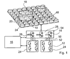
- FIG. 1 shows an induction hob with a plurality of heating elements, which are arranged in a matrix.
- the heating elements are inductors 10, which are operated by two power electronics modules 24.
- the power electronics modules 24 generate a high-frequency heating current and are connected via a switching arrangement 14 with the inductors 10.
- the switching arrangement 14 serves to establish and disconnect the connection between the power electronics module 24 and the heating elements formed as inductors 10 and comprises a number of electromechanical relays 26 or semiconductor relays.
- the induction hob has a matrix of 64 in total inductors 10 arranged in a square grid with 8 x 8 points.
- a control unit 16 of the induction hob controls the operation of inverters 12 of the power electronics assembly 24 and actuates the switching assembly 14 such that the control unit 16 summarizes arranged in a vicinity of a bottom of a cookware 18 inductors 10 to flexibly definable heating zones 20.
- the combined to a heating zone 20 inductors 10 are operated by the control unit 16 for heating the cooking utensil element 18 in a coordinated manner.
- the combined to the heating zone 20 inductors 10 are operated in particular so that destructive interference between the inductors and a hum of the induction cooktop are avoided.
- the heating frequencies of the heating currents are matched to one another, preferably the inductors 10 of a heating zone 20 are operated at the same heating frequency, or a minimum distance of about 25 kHz between the heating frequencies is maintained, so that a resulting intermodulation frequency is outside of an audible frequency range for humans lies.
- the number of inverters 12 in the power electronics assembly 24 of the induction hob is far smaller than the number of inductors 10.
- each of a total of four groups of inductors 10 is associated with an inverter 12.
- the elements of the switching arrangement 14 are mounted on a separate board 28 carrying a separate assembly 54 from the power electronics assembly 24.
- Fig. 2 shows an interconnection of the inverters 12 with the inductors 10 via the switching arrangement 14.
- the inductors 10 of a group are connected in parallel and the switching arrangement 14 comprises, for each inductor 10, a relay 26, which in a first switching position a conductive connection between the inverter 12 and the Inductor 10 produces and interrupts this conductive connection in a second switching position.
- the control unit 16 can generate currents for activating electromagnets of the relays 26 via control lines and thus actuate the electromagnets of the relays 26 independently of one another in order to activate this inductor 10 by establishing the connection between the inverter 12 and the inductor 10.
- Fig. 3 shows one of the power electronics modules 24 FIG. 1 in a more detailed presentation.
- the power electronics module 24 includes two inverters 12 for generating the heating current.
- the inverters 12 are in the in FIG. 1 illustrated embodiment half-bridge inverter.
- a rectifier 30, a filter circuit 32 and an interface 34 to a household power grid 36 are integrated into the power electronics module 24.
- Fig. 4 shows the switching arrangement 14 from Fig. 1 in a more detailed presentation.
- the switching arrangement 14 has a multiplicity of output interfaces 38, which can be connected to one inductor 10 each.
- the inductors 10 can be controlled independently of each other in this way.
- a plurality of capacitors 40 is integrated into the switching arrangement 14, which are each arranged between a relay 26 and an output interface 38. Via the output interface 38, the capacitors 40 are each associated with one of the inductors 10, and the capacitors 40 complete the respective inductor 10 to a series resonant circuit whose resonant frequency is in the range of the frequency of the heating current, which is of the order of 75kHz.
- the assembly 54 of the switching arrangement 14 further comprises a pot detection circuit 42, which can also be connected via the relay 26 to the inductors 10.
- the pot detection circuit 42 generates low-voltage measuring pulses, which generates an oscillation in one of the series resonant circuits formed by the inductors 10 and the capacitors 40. From an attenuation of this oscillation is closed to the presence of a cooking pot 18 and a degree of coverage between the saucepan 18 and the inductor 10 in question.
- the control unit 16 can evaluate the signals of the pot detection circuit 42.
- a microcontroller 44 for actuating the switching elements or relays 26 of the switching arrangement 14 and a readout circuit 46 are integrated into the assembly 54 of the switching arrangement 14.
- the inductors 10 each carry one in their centers Fig. 1 shown temperature sensor 48, the measured values are read out by the read-out circuit 46 and translated into a pulse width modulated or frequency-coded signal.
- the power electronics module 24 and the assembly 54 of the switching assembly 14 each comprise two complementary connector means 50, 52.
- the first connector means 50 is an interface for transmitting low-voltage control signals and serves to establish a communication connection between the power electronics module 24 and the assembly 54 of Switching arrangement 14.
- the second connector means 52 connects the inverters 12 to the inputs of Switching units 26 of the switching arrangement 14 and is designed to transmit the heating currents whose amplitude is of the order of 100V.
Landscapes
- Physics & Mathematics (AREA)
- Electromagnetism (AREA)
- Induction Heating Cooking Devices (AREA)
- Inverter Devices (AREA)
Claims (9)
- Plaque de cuisson, notamment plaque de cuisson à induction, comprenant plusieurs éléments chauffants (10), au moins un module d'électronique de puissance (24) destiné à générer un courant de chauffage pour le fonctionnement des éléments chauffants (10) et comprenant un dispositif de commutation (14) destiné à établir et couper une liaison entre le module d'électronique de puissance (24) et les éléments chauffants (10),
caractérisée en ce que le dispositif de commutation (14) est réalisé en tant qu'un ensemble (54) séparé du module d'électronique de puissance (24). - Plaque de cuisson selon la revendication 1, caractérisée en ce que les éléments chauffants (10) sont des inducteurs et en ce que le module d'électronique de puissance (24) comprend au moins un convertisseur continu-alternatif (12) destiné à générer le courant de chauffage.
- Plaque de cuisson selon la revendication 2, caractérisée en ce que le module d'électronique de puissance (24) comprend au moins deux convertisseurs continu-alternatif (12).
- Plaque de cuisson selon l'une quelconque des revendications précédentes, caractérisée en ce que le dispositif de commutation (14) comprend une pluralité de condensateurs (40) qui sont respectivement attribués à un élément chauffant (10) réalisé comme inducteur.
- Plaque de cuisson selon l'une quelconque des revendications précédentes, caractérisée en ce que l'ensemble (54) du dispositif de commutation (14) comprend un circuit de détection de faitout (42).
- Plaque de cuisson selon l'une quelconque des revendications précédentes, caractérisée en ce que l'ensemble (54) du dispositif de commutation (14) comprend un microcontrôleur (44) destiné au fonctionnement d'éléments de commutation (26) du dispositif de commutation (14).
- Plaque de cuisson selon l'une quelconque des revendications précédentes, caractérisée par des capteurs de température (48) qui sont installés sur les éléments chauffants (10) réalisés comme inducteurs, et par un circuit de lecture (46) intégré dans l'ensemble (54) du dispositif de commutation (14), destiné à lire des valeurs de mesure des capteurs de température (48).
- Plaque de cuisson selon l'une quelconque des revendications précédentes, caractérisée en ce que le module d'électronique de puissance (24) et/ou l'ensemble (54) du dispositif de commutation (14) comprennent au moins un moyen de connexion par fiche (50, 52) destiné à établir une liaison de communication et/ou une liaison de la ligne de courant entre le module d'électronique de puissance (24) et l'ensemble (54) du dispositif de commutation (14).
- Plaque de cuisson selon l'une quelconque des revendications précédentes, caractérisée en ce que le module d'électronique de puissance (24) comprend un redresseur (30), un circuit de filtrage (32) et une interface (34) vers un réseau de courant domestique (36).
Priority Applications (1)
| Application Number | Priority Date | Filing Date | Title |
|---|---|---|---|
| PL09774881T PL2380399T3 (pl) | 2008-12-19 | 2009-12-09 | Płyta kuchenna z wieloma elementami grzejnymi i przynajmniej jednym modułem elektroniki mocy |
Applications Claiming Priority (2)
| Application Number | Priority Date | Filing Date | Title |
|---|---|---|---|
| ES200803707A ES2352772B1 (es) | 2008-12-19 | 2008-12-19 | Campo de cocción con varios elementos de calentamiento y al menos un grupo constructivo de la electrónica de potencia. |
| PCT/EP2009/066668 WO2010069825A1 (fr) | 2008-12-19 | 2009-12-09 | Table de cuisson comprenant plusieurs éléments chauffants et au moins un module d'électronique de puissance |
Publications (2)
| Publication Number | Publication Date |
|---|---|
| EP2380399A1 EP2380399A1 (fr) | 2011-10-26 |
| EP2380399B1 true EP2380399B1 (fr) | 2012-10-10 |
Family
ID=42101476
Family Applications (1)
| Application Number | Title | Priority Date | Filing Date |
|---|---|---|---|
| EP20090774881 Active EP2380399B1 (fr) | 2008-12-19 | 2009-12-09 | Table de cuisson comprenant plusieurs éléments chauffants et au moins un module d'électronique de puissance |
Country Status (7)
| Country | Link |
|---|---|
| US (1) | US9113503B2 (fr) |
| EP (1) | EP2380399B1 (fr) |
| KR (1) | KR101639461B1 (fr) |
| CN (2) | CN102257877A (fr) |
| ES (2) | ES2352772B1 (fr) |
| PL (1) | PL2380399T3 (fr) |
| WO (1) | WO2010069825A1 (fr) |
Cited By (1)
| Publication number | Priority date | Publication date | Assignee | Title |
|---|---|---|---|---|
| US11612020B2 (en) | 2018-06-25 | 2023-03-21 | Samsung Electronics Co., Ltd. | Cooking apparatus and method for controlling thereof |
Families Citing this family (31)
| Publication number | Priority date | Publication date | Assignee | Title |
|---|---|---|---|---|
| US8754351B2 (en) | 2010-11-30 | 2014-06-17 | Bose Corporation | Induction cooking |
| CN103891400B (zh) * | 2011-11-04 | 2016-03-30 | Bsh家用电器有限公司 | 感应加热装置 |
| KR101970524B1 (ko) * | 2012-03-21 | 2019-04-19 | 엘지전자 주식회사 | 유도 가열 조리 장치 및 이의 제어 방법 |
| ES2430039B1 (es) * | 2012-05-11 | 2014-10-02 | Bsh Electrodomésticos España, S.A. | Aparato de cocción con una unidad de calentamiento |
| CN103836681B (zh) * | 2012-11-23 | 2017-08-04 | 美的集团股份有限公司 | 电磁灶的锅具检测方法及电磁灶 |
| US20160029439A1 (en) * | 2013-04-10 | 2016-01-28 | Panasonic Intellectual Property Management Co., Ltd. | Induction heater |
| US9470423B2 (en) | 2013-12-02 | 2016-10-18 | Bose Corporation | Cooktop power control system |
| ES2538605B1 (es) * | 2013-12-20 | 2016-04-15 | Bsh Electrodomésticos España, S.A. | Dispositivo de campo de cocción |
| ES2544503B1 (es) * | 2014-02-28 | 2016-06-09 | Bsh Electrodomésticos España, S.A. | Procedimiento para la regulación de la temperatura de un campo de cocción |
| EP3123816B1 (fr) * | 2014-03-24 | 2017-12-27 | BSH Hausgeräte GmbH | Dispositif pour appareil de cuisson avec unité de pontage à commande automatique |
| USD787041S1 (en) | 2015-09-17 | 2017-05-16 | Whirlpool Corporation | Gas burner |
| US10837651B2 (en) | 2015-09-24 | 2020-11-17 | Whirlpool Corporation | Oven cavity connector for operating power accessory trays for cooking appliance |
| US11777190B2 (en) | 2015-12-29 | 2023-10-03 | Whirlpool Corporation | Appliance including an antenna using a portion of appliance as a ground plane |
| CN105757731B (zh) * | 2016-04-19 | 2018-05-01 | 广东美的厨房电器制造有限公司 | 电磁炉及电磁炉的控制方法 |
| CN105757730B (zh) * | 2016-04-19 | 2018-03-06 | 广东美的厨房电器制造有限公司 | 电磁炉 |
| US10145568B2 (en) | 2016-06-27 | 2018-12-04 | Whirlpool Corporation | High efficiency high power inner flame burner |
| KR102713158B1 (ko) | 2016-12-08 | 2024-10-07 | 삼성전자주식회사 | 조리 장치 |
| US10551056B2 (en) | 2017-02-23 | 2020-02-04 | Whirlpool Corporation | Burner base |
| US10451290B2 (en) | 2017-03-07 | 2019-10-22 | Whirlpool Corporation | Forced convection steam assembly |
| US10660162B2 (en) | 2017-03-16 | 2020-05-19 | Whirlpool Corporation | Power delivery system for an induction cooktop with multi-output inverters |
| KR102413858B1 (ko) * | 2017-08-31 | 2022-06-28 | 엘지전자 주식회사 | 제어 알고리즘이 개선된 유도 가열 및 무선 전력 전송 장치 |
| KR102016219B1 (ko) * | 2017-09-29 | 2019-08-29 | 엘지전자 주식회사 | 대상체 검출 알고리즘이 개선된 유도 가열 및 무선 전력 전송 장치 |
| EP3474630B1 (fr) * | 2017-10-19 | 2024-06-26 | LG Electronics Inc. | Dispositif de chauffage par induction ayant une meilleure précision de détection d'objet cible et système de chauffage par induction le comprenant |
| ES2719129A1 (es) * | 2018-01-08 | 2019-07-08 | Bsh Electrodomesticos Espana Sa | Dispositivo de campo de coccion |
| US10627116B2 (en) | 2018-06-26 | 2020-04-21 | Whirlpool Corporation | Ventilation system for cooking appliance |
| US10619862B2 (en) | 2018-06-28 | 2020-04-14 | Whirlpool Corporation | Frontal cooling towers for a ventilation system of a cooking appliance |
| US10837652B2 (en) | 2018-07-18 | 2020-11-17 | Whirlpool Corporation | Appliance secondary door |
| KR102734353B1 (ko) * | 2019-04-18 | 2024-11-25 | 엘지전자 주식회사 | 사용자 경험 및 사용자 인터페이스가 개선된 유도 가열 장치 |
| KR102835207B1 (ko) | 2020-02-27 | 2025-07-16 | 엘지전자 주식회사 | 유도 가열 구현 가능한 무선 전력 전송 장치 및 그의 제어 방법 |
| KR102822543B1 (ko) * | 2020-02-27 | 2025-06-18 | 엘지전자 주식회사 | 유도 가열 구현 가능한 무선 전력 전송 장치 및 그의 제어 방법 |
| KR102859350B1 (ko) * | 2020-10-12 | 2025-09-12 | 삼성전자주식회사 | 무선 전력을 전송하는 전자 장치와 이의 동작 방법 |
Family Cites Families (17)
| Publication number | Priority date | Publication date | Assignee | Title |
|---|---|---|---|---|
| FR2650669B1 (fr) * | 1989-08-04 | 1993-10-29 | Equipement Menager Cie Europ | Dispositif de mesure de temperature pour appareil de cuisson a induction et appareil comportant un tel dispositif |
| FR2728132A1 (fr) * | 1994-12-09 | 1996-06-14 | Bonnet Sa | Dispositif de chauffage par induction de recipient et procede de commande d'un tel dispositif |
| ES2128958B1 (es) * | 1996-11-21 | 2000-01-16 | Balay Sa | Procedimiento de control de potencia en cocinas de induccion alimentadas mediante inversores multipuente reconfigurables. |
| FR2758934B1 (fr) | 1997-01-24 | 1999-04-23 | Europ Equip Menager | Foyer de cuisson par induction multi-usages |
| ES2143430B1 (es) | 1998-09-08 | 2000-12-16 | Balay Sa | Circuito inversor de dos salidas, y circuito y procedimiento de control de la potencia entregada en las salidas del inversor. |
| FR2792158B1 (fr) * | 1999-04-09 | 2001-05-18 | Jaeger Regulation | Foyer de cuisson par induction modulable a rayonnement reduit et procede de realisation |
| US6894255B2 (en) * | 2002-03-22 | 2005-05-17 | Matsushita Electric Industrial Co., Ltd. | Induction heating apparatus |
| JP3730594B2 (ja) | 2002-05-22 | 2006-01-05 | 株式会社日立製作所 | 電磁誘導加熱装置 |
| CA2561810C (fr) * | 2004-04-01 | 2012-11-27 | Simona Ioffe | Appareil d'alimentation d'un instrument musical electronique |
| WO2006032292A1 (fr) * | 2004-09-23 | 2006-03-30 | E.G.O. Elektro-Gerätebau GmbH | Dispositif de chauffage pour un chauffage plan, pourvu d'elements chauffants a induction |
| JP4310293B2 (ja) | 2005-05-30 | 2009-08-05 | 日立アプライアンス株式会社 | 誘導加熱装置 |
| CN2814872Y (zh) * | 2005-07-28 | 2006-09-06 | 西安博大电炉有限公司 | 中频感应加热功率调节装置 |
| DE102005050036A1 (de) | 2005-10-14 | 2007-05-31 | E.G.O. Elektro-Gerätebau GmbH | Induktionsheizeinrichtung und zugehöriges Betriebs- und Topferkennungsverfahren |
| ES2300168B1 (es) * | 2005-10-27 | 2009-05-08 | Bsh Electrodomesticos España, S.A. | Encimera de cocina y procedimiento para el funcionamiento de una encimera de cocina. |
| GB2431999B (en) * | 2005-11-04 | 2008-01-16 | Siemens Magnet Technology Ltd | Switching circuit for controlling multiple heating elements |
| ES2310962B1 (es) * | 2006-12-04 | 2009-10-23 | Bsh Electrodomesticos España, S.A. | Circuito de dispositivo de calentamiento. |
| KR20090057495A (ko) * | 2007-12-03 | 2009-06-08 | 삼성전자주식회사 | 유도가열조리기 및 그 제어방법 |
-
2008
- 2008-12-19 ES ES200803707A patent/ES2352772B1/es not_active Expired - Fee Related
-
2009
- 2009-12-09 US US13/131,912 patent/US9113503B2/en not_active Expired - Fee Related
- 2009-12-09 KR KR1020117016664A patent/KR101639461B1/ko not_active Expired - Fee Related
- 2009-12-09 CN CN2009801510352A patent/CN102257877A/zh active Pending
- 2009-12-09 ES ES09774881T patent/ES2393846T3/es active Active
- 2009-12-09 EP EP20090774881 patent/EP2380399B1/fr active Active
- 2009-12-09 PL PL09774881T patent/PL2380399T3/pl unknown
- 2009-12-09 CN CN201510630088.XA patent/CN105228280A/zh active Pending
- 2009-12-09 WO PCT/EP2009/066668 patent/WO2010069825A1/fr not_active Ceased
Cited By (1)
| Publication number | Priority date | Publication date | Assignee | Title |
|---|---|---|---|---|
| US11612020B2 (en) | 2018-06-25 | 2023-03-21 | Samsung Electronics Co., Ltd. | Cooking apparatus and method for controlling thereof |
Also Published As
| Publication number | Publication date |
|---|---|
| CN105228280A (zh) | 2016-01-06 |
| PL2380399T3 (pl) | 2013-03-29 |
| ES2352772A1 (es) | 2011-02-23 |
| KR20110103427A (ko) | 2011-09-20 |
| US20110226756A1 (en) | 2011-09-22 |
| EP2380399A1 (fr) | 2011-10-26 |
| ES2352772B1 (es) | 2012-01-26 |
| KR101639461B1 (ko) | 2016-07-13 |
| CN102257877A (zh) | 2011-11-23 |
| US9113503B2 (en) | 2015-08-18 |
| ES2393846T3 (es) | 2012-12-28 |
| WO2010069825A1 (fr) | 2010-06-24 |
Similar Documents
| Publication | Publication Date | Title |
|---|---|---|
| EP2380399B1 (fr) | Table de cuisson comprenant plusieurs éléments chauffants et au moins un module d'électronique de puissance | |
| EP2380400B1 (fr) | Plaque de cuisson à induction et procédé d'utilisation d'une plaque de cuisson à induction | |
| EP1943878B1 (fr) | Plaque de cuisson et procede permettant de faire fonctionner une plaque de cuisson | |
| EP2342943B1 (fr) | Plaque de cuisson et procédé permettant de faire fonctionner une plaque de cuisson | |
| EP3518618B1 (fr) | Plaque de cuisson pourvue d'au moins deux zones chauffantes | |
| EP0883327B1 (fr) | Arrangement pour la transmission sans fil de la température et pour la détection d'un récipient de cuisson sur une cuisinière | |
| EP2494846B1 (fr) | Plaque de cuisson à au moins deux résistances, et dispositif électronique de puissance | |
| EP0687131A2 (fr) | Système de commande pour appareil de chauffage électrique | |
| EP2380398A1 (fr) | Table de cuisson avec au moins un inducteur, au moins un onduleur et un dispositif de commutation | |
| EP3085201A1 (fr) | Dispositif pour plaque de cuisson | |
| WO2006032292A1 (fr) | Dispositif de chauffage pour un chauffage plan, pourvu d'elements chauffants a induction | |
| EP4070695A1 (fr) | Ustensile de cuisine destiné à être posé sur une plaque de cuisson à induction, procédé de fonctionnement de l'ustensile de cuisine, procédé de fonctionnement de la coque intérieure de l'ustensile de cuisine et procédé de fonctionnement d'un système | |
| EP2127479B1 (fr) | Dispositif pour convertir de l'énergie électrique transmise par induction et procédé de production d'un tel dispositif | |
| EP2888925B1 (fr) | Appareil électroménager | |
| EP3066888B1 (fr) | Dispositif table de cuisson à induction | |
| DE102004059822A1 (de) | Sensorvorrichtung für ein Kochfeld, Verfahren zum Betrieb einer Sensorvorrichtung und Verwendung eines Temperatursensors als Topferkennungssensor | |
| DE102013207786A1 (de) | Hausgeräteinduktionsheizvorrichtung | |
| EP2741571B1 (fr) | Dispositif de champ de cuisson | |
| WO2023057205A1 (fr) | Système de transmission d'énergie par induction | |
| EP2219500A1 (fr) | Batterie de cuisine | |
| WO2008031560A1 (fr) | Système de chauffage par induction | |
| EP4287770A1 (fr) | Plaque de cuisson à induction comprenant une structure de support dotée d'antennes et/ou de capteurs, procédé de fabrication d'une telle structure de support et utilisation d'une structure de support pour plaque de cuisson à induction | |
| DE102006023719B4 (de) | Heizkörper für eine Kochmulde | |
| EP2749124A2 (fr) | Appareil ménager |
Legal Events
| Date | Code | Title | Description |
|---|---|---|---|
| PUAI | Public reference made under article 153(3) epc to a published international application that has entered the european phase |
Free format text: ORIGINAL CODE: 0009012 |
|
| 17P | Request for examination filed |
Effective date: 20110719 |
|
| AK | Designated contracting states |
Kind code of ref document: A1 Designated state(s): AT BE BG CH CY CZ DE DK EE ES FI FR GB GR HR HU IE IS IT LI LT LU LV MC MK MT NL NO PL PT RO SE SI SK SM TR |
|
| DAX | Request for extension of the european patent (deleted) | ||
| GRAP | Despatch of communication of intention to grant a patent |
Free format text: ORIGINAL CODE: EPIDOSNIGR1 |
|
| GRAS | Grant fee paid |
Free format text: ORIGINAL CODE: EPIDOSNIGR3 |
|
| GRAA | (expected) grant |
Free format text: ORIGINAL CODE: 0009210 |
|
| AK | Designated contracting states |
Kind code of ref document: B1 Designated state(s): AT BE BG CH CY CZ DE DK EE ES FI FR GB GR HR HU IE IS IT LI LT LU LV MC MK MT NL NO PL PT RO SE SI SK SM TR |
|
| REG | Reference to a national code |
Ref country code: GB Ref legal event code: FG4D Free format text: NOT ENGLISH |
|
| REG | Reference to a national code |
Ref country code: AT Ref legal event code: REF Ref document number: 579445 Country of ref document: AT Kind code of ref document: T Effective date: 20121015 Ref country code: CH Ref legal event code: EP |
|
| REG | Reference to a national code |
Ref country code: IE Ref legal event code: FG4D Free format text: LANGUAGE OF EP DOCUMENT: GERMAN |
|
| REG | Reference to a national code |
Ref country code: DE Ref legal event code: R096 Ref document number: 502009005059 Country of ref document: DE Effective date: 20121213 |
|
| REG | Reference to a national code |
Ref country code: ES Ref legal event code: FG2A Ref document number: 2393846 Country of ref document: ES Kind code of ref document: T3 Effective date: 20121228 |
|
| PG25 | Lapsed in a contracting state [announced via postgrant information from national office to epo] |
Ref country code: SI Free format text: LAPSE BECAUSE OF FAILURE TO SUBMIT A TRANSLATION OF THE DESCRIPTION OR TO PAY THE FEE WITHIN THE PRESCRIBED TIME-LIMIT Effective date: 20121010 |
|
| REG | Reference to a national code |
Ref country code: NL Ref legal event code: VDEP Effective date: 20121010 |
|
| REG | Reference to a national code |
Ref country code: LT Ref legal event code: MG4D |
|
| REG | Reference to a national code |
Ref country code: PL Ref legal event code: T3 |
|
| PG25 | Lapsed in a contracting state [announced via postgrant information from national office to epo] |
Ref country code: LT Free format text: LAPSE BECAUSE OF FAILURE TO SUBMIT A TRANSLATION OF THE DESCRIPTION OR TO PAY THE FEE WITHIN THE PRESCRIBED TIME-LIMIT Effective date: 20121010 Ref country code: SE Free format text: LAPSE BECAUSE OF FAILURE TO SUBMIT A TRANSLATION OF THE DESCRIPTION OR TO PAY THE FEE WITHIN THE PRESCRIBED TIME-LIMIT Effective date: 20121010 Ref country code: HR Free format text: LAPSE BECAUSE OF FAILURE TO SUBMIT A TRANSLATION OF THE DESCRIPTION OR TO PAY THE FEE WITHIN THE PRESCRIBED TIME-LIMIT Effective date: 20121010 Ref country code: NO Free format text: LAPSE BECAUSE OF FAILURE TO SUBMIT A TRANSLATION OF THE DESCRIPTION OR TO PAY THE FEE WITHIN THE PRESCRIBED TIME-LIMIT Effective date: 20130110 Ref country code: IS Free format text: LAPSE BECAUSE OF FAILURE TO SUBMIT A TRANSLATION OF THE DESCRIPTION OR TO PAY THE FEE WITHIN THE PRESCRIBED TIME-LIMIT Effective date: 20130210 Ref country code: NL Free format text: LAPSE BECAUSE OF FAILURE TO SUBMIT A TRANSLATION OF THE DESCRIPTION OR TO PAY THE FEE WITHIN THE PRESCRIBED TIME-LIMIT Effective date: 20121010 Ref country code: FI Free format text: LAPSE BECAUSE OF FAILURE TO SUBMIT A TRANSLATION OF THE DESCRIPTION OR TO PAY THE FEE WITHIN THE PRESCRIBED TIME-LIMIT Effective date: 20121010 |
|
| PG25 | Lapsed in a contracting state [announced via postgrant information from national office to epo] |
Ref country code: PT Free format text: LAPSE BECAUSE OF FAILURE TO SUBMIT A TRANSLATION OF THE DESCRIPTION OR TO PAY THE FEE WITHIN THE PRESCRIBED TIME-LIMIT Effective date: 20130211 Ref country code: LV Free format text: LAPSE BECAUSE OF FAILURE TO SUBMIT A TRANSLATION OF THE DESCRIPTION OR TO PAY THE FEE WITHIN THE PRESCRIBED TIME-LIMIT Effective date: 20121010 |
|
| BERE | Be: lapsed |
Owner name: BSH BOSCH UND SIEMENS HAUSGERATE G.M.B.H. Effective date: 20121231 |
|
| PG25 | Lapsed in a contracting state [announced via postgrant information from national office to epo] |
Ref country code: DK Free format text: LAPSE BECAUSE OF FAILURE TO SUBMIT A TRANSLATION OF THE DESCRIPTION OR TO PAY THE FEE WITHIN THE PRESCRIBED TIME-LIMIT Effective date: 20121010 Ref country code: SK Free format text: LAPSE BECAUSE OF FAILURE TO SUBMIT A TRANSLATION OF THE DESCRIPTION OR TO PAY THE FEE WITHIN THE PRESCRIBED TIME-LIMIT Effective date: 20121010 Ref country code: MC Free format text: LAPSE BECAUSE OF NON-PAYMENT OF DUE FEES Effective date: 20121231 Ref country code: BG Free format text: LAPSE BECAUSE OF FAILURE TO SUBMIT A TRANSLATION OF THE DESCRIPTION OR TO PAY THE FEE WITHIN THE PRESCRIBED TIME-LIMIT Effective date: 20130110 Ref country code: EE Free format text: LAPSE BECAUSE OF FAILURE TO SUBMIT A TRANSLATION OF THE DESCRIPTION OR TO PAY THE FEE WITHIN THE PRESCRIBED TIME-LIMIT Effective date: 20121010 Ref country code: CZ Free format text: LAPSE BECAUSE OF FAILURE TO SUBMIT A TRANSLATION OF THE DESCRIPTION OR TO PAY THE FEE WITHIN THE PRESCRIBED TIME-LIMIT Effective date: 20121010 |
|
| PLBE | No opposition filed within time limit |
Free format text: ORIGINAL CODE: 0009261 |
|
| STAA | Information on the status of an ep patent application or granted ep patent |
Free format text: STATUS: NO OPPOSITION FILED WITHIN TIME LIMIT |
|
| PG25 | Lapsed in a contracting state [announced via postgrant information from national office to epo] |
Ref country code: RO Free format text: LAPSE BECAUSE OF FAILURE TO SUBMIT A TRANSLATION OF THE DESCRIPTION OR TO PAY THE FEE WITHIN THE PRESCRIBED TIME-LIMIT Effective date: 20121010 |
|
| 26N | No opposition filed |
Effective date: 20130711 |
|
| REG | Reference to a national code |
Ref country code: IE Ref legal event code: MM4A |
|
| PG25 | Lapsed in a contracting state [announced via postgrant information from national office to epo] |
Ref country code: BE Free format text: LAPSE BECAUSE OF NON-PAYMENT OF DUE FEES Effective date: 20121231 |
|
| PG25 | Lapsed in a contracting state [announced via postgrant information from national office to epo] |
Ref country code: IE Free format text: LAPSE BECAUSE OF NON-PAYMENT OF DUE FEES Effective date: 20121209 |
|
| REG | Reference to a national code |
Ref country code: DE Ref legal event code: R097 Ref document number: 502009005059 Country of ref document: DE Effective date: 20130711 |
|
| PG25 | Lapsed in a contracting state [announced via postgrant information from national office to epo] |
Ref country code: MT Free format text: LAPSE BECAUSE OF FAILURE TO SUBMIT A TRANSLATION OF THE DESCRIPTION OR TO PAY THE FEE WITHIN THE PRESCRIBED TIME-LIMIT Effective date: 20121010 Ref country code: CY Free format text: LAPSE BECAUSE OF FAILURE TO SUBMIT A TRANSLATION OF THE DESCRIPTION OR TO PAY THE FEE WITHIN THE PRESCRIBED TIME-LIMIT Effective date: 20121010 |
|
| PG25 | Lapsed in a contracting state [announced via postgrant information from national office to epo] |
Ref country code: TR Free format text: LAPSE BECAUSE OF FAILURE TO SUBMIT A TRANSLATION OF THE DESCRIPTION OR TO PAY THE FEE WITHIN THE PRESCRIBED TIME-LIMIT Effective date: 20121010 |
|
| PG25 | Lapsed in a contracting state [announced via postgrant information from national office to epo] |
Ref country code: LU Free format text: LAPSE BECAUSE OF NON-PAYMENT OF DUE FEES Effective date: 20121209 Ref country code: SM Free format text: LAPSE BECAUSE OF FAILURE TO SUBMIT A TRANSLATION OF THE DESCRIPTION OR TO PAY THE FEE WITHIN THE PRESCRIBED TIME-LIMIT Effective date: 20121010 |
|
| PG25 | Lapsed in a contracting state [announced via postgrant information from national office to epo] |
Ref country code: HU Free format text: LAPSE BECAUSE OF FAILURE TO SUBMIT A TRANSLATION OF THE DESCRIPTION OR TO PAY THE FEE WITHIN THE PRESCRIBED TIME-LIMIT Effective date: 20091209 |
|
| PG25 | Lapsed in a contracting state [announced via postgrant information from national office to epo] |
Ref country code: GR Free format text: LAPSE BECAUSE OF FAILURE TO SUBMIT A TRANSLATION OF THE DESCRIPTION OR TO PAY THE FEE WITHIN THE PRESCRIBED TIME-LIMIT Effective date: 20121010 |
|
| REG | Reference to a national code |
Ref country code: CH Ref legal event code: PFA Owner name: BSH HAUSGERAETE GMBH, DE Free format text: FORMER OWNER: BSH BOSCH UND SIEMENS HAUSGERAETE GMBH, DE |
|
| REG | Reference to a national code |
Ref country code: DE Ref legal event code: R081 Ref document number: 502009005059 Country of ref document: DE Owner name: BSH HAUSGERAETE GMBH, DE Free format text: FORMER OWNER: BSH BOSCH UND SIEMENS HAUSGERAETE GMBH, 81739 MUENCHEN, DE Effective date: 20150409 |
|
| REG | Reference to a national code |
Ref country code: ES Ref legal event code: PC2A Owner name: BSH HAUSGERATE GMBH Effective date: 20150529 |
|
| PG25 | Lapsed in a contracting state [announced via postgrant information from national office to epo] |
Ref country code: MK Free format text: LAPSE BECAUSE OF FAILURE TO SUBMIT A TRANSLATION OF THE DESCRIPTION OR TO PAY THE FEE WITHIN THE PRESCRIBED TIME-LIMIT Effective date: 20121010 |
|
| REG | Reference to a national code |
Ref country code: FR Ref legal event code: CD Owner name: BSH HAUSGERATE GMBH, DE Effective date: 20151022 |
|
| REG | Reference to a national code |
Ref country code: FR Ref legal event code: PLFP Year of fee payment: 7 |
|
| REG | Reference to a national code |
Ref country code: AT Ref legal event code: MM01 Ref document number: 579445 Country of ref document: AT Kind code of ref document: T Effective date: 20141209 |
|
| PG25 | Lapsed in a contracting state [announced via postgrant information from national office to epo] |
Ref country code: AT Free format text: LAPSE BECAUSE OF NON-PAYMENT OF DUE FEES Effective date: 20141209 |
|
| REG | Reference to a national code |
Ref country code: FR Ref legal event code: PLFP Year of fee payment: 8 |
|
| REG | Reference to a national code |
Ref country code: FR Ref legal event code: PLFP Year of fee payment: 9 |
|
| PGFP | Annual fee paid to national office [announced via postgrant information from national office to epo] |
Ref country code: PL Payment date: 20191128 Year of fee payment: 11 |
|
| PGFP | Annual fee paid to national office [announced via postgrant information from national office to epo] |
Ref country code: CH Payment date: 20191220 Year of fee payment: 11 |
|
| REG | Reference to a national code |
Ref country code: CH Ref legal event code: PL |
|
| PG25 | Lapsed in a contracting state [announced via postgrant information from national office to epo] |
Ref country code: LI Free format text: LAPSE BECAUSE OF NON-PAYMENT OF DUE FEES Effective date: 20201231 Ref country code: CH Free format text: LAPSE BECAUSE OF NON-PAYMENT OF DUE FEES Effective date: 20201231 |
|
| PG25 | Lapsed in a contracting state [announced via postgrant information from national office to epo] |
Ref country code: PL Free format text: LAPSE BECAUSE OF NON-PAYMENT OF DUE FEES Effective date: 20201209 |
|
| PGFP | Annual fee paid to national office [announced via postgrant information from national office to epo] |
Ref country code: GB Payment date: 20251218 Year of fee payment: 17 |
|
| PGFP | Annual fee paid to national office [announced via postgrant information from national office to epo] |
Ref country code: FR Payment date: 20251218 Year of fee payment: 17 |
|
| PGFP | Annual fee paid to national office [announced via postgrant information from national office to epo] |
Ref country code: ES Payment date: 20260119 Year of fee payment: 17 |
|
| PGFP | Annual fee paid to national office [announced via postgrant information from national office to epo] |
Ref country code: DE Payment date: 20251231 Year of fee payment: 17 |
|
| PGFP | Annual fee paid to national office [announced via postgrant information from national office to epo] |
Ref country code: IT Payment date: 20251231 Year of fee payment: 17 |