EP2380524B2 - Vorrichtung und Verfahren zur Amelioration von Ausnehmungen - Google Patents
Vorrichtung und Verfahren zur Amelioration von Ausnehmungen Download PDFInfo
- Publication number
- EP2380524B2 EP2380524B2 EP11174531.1A EP11174531A EP2380524B2 EP 2380524 B2 EP2380524 B2 EP 2380524B2 EP 11174531 A EP11174531 A EP 11174531A EP 2380524 B2 EP2380524 B2 EP 2380524B2
- Authority
- EP
- European Patent Office
- Prior art keywords
- recess
- guide pin
- sleeve
- collar
- amelioration
- Prior art date
- Legal status (The legal status is an assumption and is not a legal conclusion. Google has not performed a legal analysis and makes no representation as to the accuracy of the status listed.)
- Active
Links
Images


Classifications
-
- A—HUMAN NECESSITIES
- A61—MEDICAL OR VETERINARY SCIENCE; HYGIENE
- A61B—DIAGNOSIS; SURGERY; IDENTIFICATION
- A61B17/00—Surgical instruments, devices or methods
- A61B17/56—Surgical instruments or methods for treatment of bones or joints; Devices specially adapted therefor
- A61B17/58—Surgical instruments or methods for treatment of bones or joints; Devices specially adapted therefor for osteosynthesis, e.g. bone plates, screws or setting implements
- A61B17/88—Osteosynthesis instruments; Methods or means for implanting or extracting internal or external fixation devices
-
- A—HUMAN NECESSITIES
- A61—MEDICAL OR VETERINARY SCIENCE; HYGIENE
- A61B—DIAGNOSIS; SURGERY; IDENTIFICATION
- A61B17/00—Surgical instruments, devices or methods
- A61B17/56—Surgical instruments or methods for treatment of bones or joints; Devices specially adapted therefor
- A61B17/58—Surgical instruments or methods for treatment of bones or joints; Devices specially adapted therefor for osteosynthesis, e.g. bone plates, screws or setting implements
- A61B17/68—Internal fixation devices, including fasteners and spinal fixators, even if a part thereof projects from the skin
- A61B17/686—Plugs, i.e. elements forming interface between bone hole and implant or fastener, e.g. screw
-
- A—HUMAN NECESSITIES
- A61—MEDICAL OR VETERINARY SCIENCE; HYGIENE
- A61B—DIAGNOSIS; SURGERY; IDENTIFICATION
- A61B17/00—Surgical instruments, devices or methods
- A61B17/56—Surgical instruments or methods for treatment of bones or joints; Devices specially adapted therefor
- A61B17/58—Surgical instruments or methods for treatment of bones or joints; Devices specially adapted therefor for osteosynthesis, e.g. bone plates, screws or setting implements
- A61B17/88—Osteosynthesis instruments; Methods or means for implanting or extracting internal or external fixation devices
- A61B17/8802—Equipment for handling bone cement or other fluid fillers
-
- A—HUMAN NECESSITIES
- A61—MEDICAL OR VETERINARY SCIENCE; HYGIENE
- A61B—DIAGNOSIS; SURGERY; IDENTIFICATION
- A61B17/00—Surgical instruments, devices or methods
- A61B17/56—Surgical instruments or methods for treatment of bones or joints; Devices specially adapted therefor
- A61B17/58—Surgical instruments or methods for treatment of bones or joints; Devices specially adapted therefor for osteosynthesis, e.g. bone plates, screws or setting implements
- A61B17/88—Osteosynthesis instruments; Methods or means for implanting or extracting internal or external fixation devices
- A61B17/8872—Instruments for putting said fixation devices against or away from the bone
-
- A—HUMAN NECESSITIES
- A61—MEDICAL OR VETERINARY SCIENCE; HYGIENE
- A61C—DENTISTRY; APPARATUS OR METHODS FOR ORAL OR DENTAL HYGIENE
- A61C8/00—Means to be fixed to the jaw-bone for consolidating natural teeth or for fixing dental prostheses thereon; Dental implants; Implanting tools
- A61C8/0012—Means to be fixed to the jaw-bone for consolidating natural teeth or for fixing dental prostheses thereon; Dental implants; Implanting tools characterised by the material or composition, e.g. ceramics, surface layer, metal alloy
-
- B—PERFORMING OPERATIONS; TRANSPORTING
- B29—WORKING OF PLASTICS; WORKING OF SUBSTANCES IN A PLASTIC STATE IN GENERAL
- B29C—SHAPING OR JOINING OF PLASTICS; SHAPING OF MATERIAL IN A PLASTIC STATE, NOT OTHERWISE PROVIDED FOR; AFTER-TREATMENT OF THE SHAPED PRODUCTS, e.g. REPAIRING
- B29C65/00—Joining or sealing of preformed parts, e.g. welding of plastics materials; Apparatus therefor
- B29C65/02—Joining or sealing of preformed parts, e.g. welding of plastics materials; Apparatus therefor by heating, with or without pressure
- B29C65/08—Joining or sealing of preformed parts, e.g. welding of plastics materials; Apparatus therefor by heating, with or without pressure using ultrasonic vibrations
-
- A—HUMAN NECESSITIES
- A61—MEDICAL OR VETERINARY SCIENCE; HYGIENE
- A61B—DIAGNOSIS; SURGERY; IDENTIFICATION
- A61B17/00—Surgical instruments, devices or methods
- A61B17/56—Surgical instruments or methods for treatment of bones or joints; Devices specially adapted therefor
- A61B17/58—Surgical instruments or methods for treatment of bones or joints; Devices specially adapted therefor for osteosynthesis, e.g. bone plates, screws or setting implements
- A61B17/88—Osteosynthesis instruments; Methods or means for implanting or extracting internal or external fixation devices
- A61B17/8897—Guide wires or guide pins
-
- A—HUMAN NECESSITIES
- A61—MEDICAL OR VETERINARY SCIENCE; HYGIENE
- A61B—DIAGNOSIS; SURGERY; IDENTIFICATION
- A61B17/00—Surgical instruments, devices or methods
- A61B2017/00367—Details of actuation of instruments, e.g. relations between pushing buttons, or the like, and activation of the tool, working tip, or the like
- A61B2017/00411—Details of actuation of instruments, e.g. relations between pushing buttons, or the like, and activation of the tool, working tip, or the like actuated by application of energy from an energy source outside the body
-
- A—HUMAN NECESSITIES
- A61—MEDICAL OR VETERINARY SCIENCE; HYGIENE
- A61B—DIAGNOSIS; SURGERY; IDENTIFICATION
- A61B17/00—Surgical instruments, devices or methods
- A61B2017/00831—Material properties
- A61B2017/00955—Material properties thermoplastic
-
- A—HUMAN NECESSITIES
- A61—MEDICAL OR VETERINARY SCIENCE; HYGIENE
- A61C—DENTISTRY; APPARATUS OR METHODS FOR ORAL OR DENTAL HYGIENE
- A61C8/00—Means to be fixed to the jaw-bone for consolidating natural teeth or for fixing dental prostheses thereon; Dental implants; Implanting tools
- A61C8/0089—Implanting tools or instruments
-
- B—PERFORMING OPERATIONS; TRANSPORTING
- B29—WORKING OF PLASTICS; WORKING OF SUBSTANCES IN A PLASTIC STATE IN GENERAL
- B29C—SHAPING OR JOINING OF PLASTICS; SHAPING OF MATERIAL IN A PLASTIC STATE, NOT OTHERWISE PROVIDED FOR; AFTER-TREATMENT OF THE SHAPED PRODUCTS, e.g. REPAIRING
- B29C65/00—Joining or sealing of preformed parts, e.g. welding of plastics materials; Apparatus therefor
- B29C65/02—Joining or sealing of preformed parts, e.g. welding of plastics materials; Apparatus therefor by heating, with or without pressure
- B29C65/06—Joining or sealing of preformed parts, e.g. welding of plastics materials; Apparatus therefor by heating, with or without pressure using friction, e.g. spin welding
-
- B—PERFORMING OPERATIONS; TRANSPORTING
- B29—WORKING OF PLASTICS; WORKING OF SUBSTANCES IN A PLASTIC STATE IN GENERAL
- B29C—SHAPING OR JOINING OF PLASTICS; SHAPING OF MATERIAL IN A PLASTIC STATE, NOT OTHERWISE PROVIDED FOR; AFTER-TREATMENT OF THE SHAPED PRODUCTS, e.g. REPAIRING
- B29C65/00—Joining or sealing of preformed parts, e.g. welding of plastics materials; Apparatus therefor
- B29C65/02—Joining or sealing of preformed parts, e.g. welding of plastics materials; Apparatus therefor by heating, with or without pressure
- B29C65/08—Joining or sealing of preformed parts, e.g. welding of plastics materials; Apparatus therefor by heating, with or without pressure using ultrasonic vibrations
- B29C65/081—Joining or sealing of preformed parts, e.g. welding of plastics materials; Apparatus therefor by heating, with or without pressure using ultrasonic vibrations having a component of vibration not perpendicular to the welding surface
-
- B—PERFORMING OPERATIONS; TRANSPORTING
- B29—WORKING OF PLASTICS; WORKING OF SUBSTANCES IN A PLASTIC STATE IN GENERAL
- B29C—SHAPING OR JOINING OF PLASTICS; SHAPING OF MATERIAL IN A PLASTIC STATE, NOT OTHERWISE PROVIDED FOR; AFTER-TREATMENT OF THE SHAPED PRODUCTS, e.g. REPAIRING
- B29C65/00—Joining or sealing of preformed parts, e.g. welding of plastics materials; Apparatus therefor
- B29C65/56—Joining or sealing of preformed parts, e.g. welding of plastics materials; Apparatus therefor using mechanical means or mechanical connections, e.g. form-fits
-
- B—PERFORMING OPERATIONS; TRANSPORTING
- B29—WORKING OF PLASTICS; WORKING OF SUBSTANCES IN A PLASTIC STATE IN GENERAL
- B29C—SHAPING OR JOINING OF PLASTICS; SHAPING OF MATERIAL IN A PLASTIC STATE, NOT OTHERWISE PROVIDED FOR; AFTER-TREATMENT OF THE SHAPED PRODUCTS, e.g. REPAIRING
- B29C66/00—General aspects of processes or apparatus for joining preformed parts
- B29C66/01—General aspects dealing with the joint area or with the area to be joined
- B29C66/05—Particular design of joint configurations
- B29C66/303—Particular design of joint configurations the joint involving an anchoring effect
- B29C66/3032—Particular design of joint configurations the joint involving an anchoring effect making use of protrusions or cavities belonging to at least one of the parts to be joined
- B29C66/30325—Particular design of joint configurations the joint involving an anchoring effect making use of protrusions or cavities belonging to at least one of the parts to be joined making use of cavities belonging to at least one of the parts to be joined
- B29C66/30326—Particular design of joint configurations the joint involving an anchoring effect making use of protrusions or cavities belonging to at least one of the parts to be joined making use of cavities belonging to at least one of the parts to be joined in the form of porosity
-
- B—PERFORMING OPERATIONS; TRANSPORTING
- B29—WORKING OF PLASTICS; WORKING OF SUBSTANCES IN A PLASTIC STATE IN GENERAL
- B29C—SHAPING OR JOINING OF PLASTICS; SHAPING OF MATERIAL IN A PLASTIC STATE, NOT OTHERWISE PROVIDED FOR; AFTER-TREATMENT OF THE SHAPED PRODUCTS, e.g. REPAIRING
- B29C66/00—General aspects of processes or apparatus for joining preformed parts
- B29C66/50—General aspects of joining tubular articles; General aspects of joining long products, i.e. bars or profiled elements; General aspects of joining single elements to tubular articles, hollow articles or bars; General aspects of joining several hollow-preforms to form hollow or tubular articles
- B29C66/51—Joining tubular articles, profiled elements or bars; Joining single elements to tubular articles, hollow articles or bars; Joining several hollow-preforms to form hollow or tubular articles
- B29C66/53—Joining single elements to tubular articles, hollow articles or bars
- B29C66/532—Joining single elements to the wall of tubular articles, hollow articles or bars
-
- B—PERFORMING OPERATIONS; TRANSPORTING
- B29—WORKING OF PLASTICS; WORKING OF SUBSTANCES IN A PLASTIC STATE IN GENERAL
- B29C—SHAPING OR JOINING OF PLASTICS; SHAPING OF MATERIAL IN A PLASTIC STATE, NOT OTHERWISE PROVIDED FOR; AFTER-TREATMENT OF THE SHAPED PRODUCTS, e.g. REPAIRING
- B29C66/00—General aspects of processes or apparatus for joining preformed parts
- B29C66/70—General aspects of processes or apparatus for joining preformed parts characterised by the composition, physical properties or the structure of the material of the parts to be joined; Joining with non-plastics material
- B29C66/71—General aspects of processes or apparatus for joining preformed parts characterised by the composition, physical properties or the structure of the material of the parts to be joined; Joining with non-plastics material characterised by the composition of the plastics material of the parts to be joined
-
- B—PERFORMING OPERATIONS; TRANSPORTING
- B29—WORKING OF PLASTICS; WORKING OF SUBSTANCES IN A PLASTIC STATE IN GENERAL
- B29C—SHAPING OR JOINING OF PLASTICS; SHAPING OF MATERIAL IN A PLASTIC STATE, NOT OTHERWISE PROVIDED FOR; AFTER-TREATMENT OF THE SHAPED PRODUCTS, e.g. REPAIRING
- B29C66/00—General aspects of processes or apparatus for joining preformed parts
- B29C66/70—General aspects of processes or apparatus for joining preformed parts characterised by the composition, physical properties or the structure of the material of the parts to be joined; Joining with non-plastics material
- B29C66/72—General aspects of processes or apparatus for joining preformed parts characterised by the composition, physical properties or the structure of the material of the parts to be joined; Joining with non-plastics material characterised by the structure of the material of the parts to be joined
- B29C66/727—General aspects of processes or apparatus for joining preformed parts characterised by the composition, physical properties or the structure of the material of the parts to be joined; Joining with non-plastics material characterised by the structure of the material of the parts to be joined being porous, e.g. foam
-
- B—PERFORMING OPERATIONS; TRANSPORTING
- B29—WORKING OF PLASTICS; WORKING OF SUBSTANCES IN A PLASTIC STATE IN GENERAL
- B29C—SHAPING OR JOINING OF PLASTICS; SHAPING OF MATERIAL IN A PLASTIC STATE, NOT OTHERWISE PROVIDED FOR; AFTER-TREATMENT OF THE SHAPED PRODUCTS, e.g. REPAIRING
- B29C66/00—General aspects of processes or apparatus for joining preformed parts
- B29C66/70—General aspects of processes or apparatus for joining preformed parts characterised by the composition, physical properties or the structure of the material of the parts to be joined; Joining with non-plastics material
- B29C66/73—General aspects of processes or apparatus for joining preformed parts characterised by the composition, physical properties or the structure of the material of the parts to be joined; Joining with non-plastics material characterised by the intensive physical properties of the material of the parts to be joined, by the optical properties of the material of the parts to be joined, by the extensive physical properties of the parts to be joined, by the state of the material of the parts to be joined or by the material of the parts to be joined being a thermoplastic or a thermoset
- B29C66/737—General aspects of processes or apparatus for joining preformed parts characterised by the composition, physical properties or the structure of the material of the parts to be joined; Joining with non-plastics material characterised by the intensive physical properties of the material of the parts to be joined, by the optical properties of the material of the parts to be joined, by the extensive physical properties of the parts to be joined, by the state of the material of the parts to be joined or by the material of the parts to be joined being a thermoplastic or a thermoset characterised by the state of the material of the parts to be joined
- B29C66/7379—General aspects of processes or apparatus for joining preformed parts characterised by the composition, physical properties or the structure of the material of the parts to be joined; Joining with non-plastics material characterised by the intensive physical properties of the material of the parts to be joined, by the optical properties of the material of the parts to be joined, by the extensive physical properties of the parts to be joined, by the state of the material of the parts to be joined or by the material of the parts to be joined being a thermoplastic or a thermoset characterised by the state of the material of the parts to be joined degradable
- B29C66/73791—General aspects of processes or apparatus for joining preformed parts characterised by the composition, physical properties or the structure of the material of the parts to be joined; Joining with non-plastics material characterised by the intensive physical properties of the material of the parts to be joined, by the optical properties of the material of the parts to be joined, by the extensive physical properties of the parts to be joined, by the state of the material of the parts to be joined or by the material of the parts to be joined being a thermoplastic or a thermoset characterised by the state of the material of the parts to be joined degradable biodegradable
-
- B—PERFORMING OPERATIONS; TRANSPORTING
- B29—WORKING OF PLASTICS; WORKING OF SUBSTANCES IN A PLASTIC STATE IN GENERAL
- B29C—SHAPING OR JOINING OF PLASTICS; SHAPING OF MATERIAL IN A PLASTIC STATE, NOT OTHERWISE PROVIDED FOR; AFTER-TREATMENT OF THE SHAPED PRODUCTS, e.g. REPAIRING
- B29C66/00—General aspects of processes or apparatus for joining preformed parts
- B29C66/70—General aspects of processes or apparatus for joining preformed parts characterised by the composition, physical properties or the structure of the material of the parts to be joined; Joining with non-plastics material
- B29C66/74—Joining plastics material to non-plastics material
- B29C66/748—Joining plastics material to non-plastics material to natural products or their composites, not provided for in groups B29C66/742 - B29C66/746
- B29C66/7487—Wood
-
- B—PERFORMING OPERATIONS; TRANSPORTING
- B29—WORKING OF PLASTICS; WORKING OF SUBSTANCES IN A PLASTIC STATE IN GENERAL
- B29C—SHAPING OR JOINING OF PLASTICS; SHAPING OF MATERIAL IN A PLASTIC STATE, NOT OTHERWISE PROVIDED FOR; AFTER-TREATMENT OF THE SHAPED PRODUCTS, e.g. REPAIRING
- B29C66/00—General aspects of processes or apparatus for joining preformed parts
- B29C66/80—General aspects of machine operations or constructions and parts thereof
- B29C66/83—General aspects of machine operations or constructions and parts thereof characterised by the movement of the joining or pressing tools
- B29C66/832—Reciprocating joining or pressing tools
- B29C66/8322—Joining or pressing tools reciprocating along one axis
-
- B—PERFORMING OPERATIONS; TRANSPORTING
- B29—WORKING OF PLASTICS; WORKING OF SUBSTANCES IN A PLASTIC STATE IN GENERAL
- B29K—INDEXING SCHEME ASSOCIATED WITH SUBCLASSES B29B, B29C OR B29D, RELATING TO MOULDING MATERIALS OR TO MATERIALS FOR MOULDS, REINFORCEMENTS, FILLERS OR PREFORMED PARTS, e.g. INSERTS
- B29K2005/00—Use of polysaccharides or derivatives as moulding material
-
- B—PERFORMING OPERATIONS; TRANSPORTING
- B29—WORKING OF PLASTICS; WORKING OF SUBSTANCES IN A PLASTIC STATE IN GENERAL
- B29K—INDEXING SCHEME ASSOCIATED WITH SUBCLASSES B29B, B29C OR B29D, RELATING TO MOULDING MATERIALS OR TO MATERIALS FOR MOULDS, REINFORCEMENTS, FILLERS OR PREFORMED PARTS, e.g. INSERTS
- B29K2023/00—Use of polyalkenes or derivatives thereof as moulding material
- B29K2023/04—Polymers of ethylene
- B29K2023/06—PE, i.e. polyethylene
- B29K2023/0608—PE, i.e. polyethylene characterised by its density
- B29K2023/0633—LDPE, i.e. low density polyethylene
-
- B—PERFORMING OPERATIONS; TRANSPORTING
- B29—WORKING OF PLASTICS; WORKING OF SUBSTANCES IN A PLASTIC STATE IN GENERAL
- B29K—INDEXING SCHEME ASSOCIATED WITH SUBCLASSES B29B, B29C OR B29D, RELATING TO MOULDING MATERIALS OR TO MATERIALS FOR MOULDS, REINFORCEMENTS, FILLERS OR PREFORMED PARTS, e.g. INSERTS
- B29K2023/00—Use of polyalkenes or derivatives thereof as moulding material
- B29K2023/04—Polymers of ethylene
- B29K2023/06—PE, i.e. polyethylene
- B29K2023/0608—PE, i.e. polyethylene characterised by its density
- B29K2023/065—HDPE, i.e. high density polyethylene
-
- B—PERFORMING OPERATIONS; TRANSPORTING
- B29—WORKING OF PLASTICS; WORKING OF SUBSTANCES IN A PLASTIC STATE IN GENERAL
- B29K—INDEXING SCHEME ASSOCIATED WITH SUBCLASSES B29B, B29C OR B29D, RELATING TO MOULDING MATERIALS OR TO MATERIALS FOR MOULDS, REINFORCEMENTS, FILLERS OR PREFORMED PARTS, e.g. INSERTS
- B29K2023/00—Use of polyalkenes or derivatives thereof as moulding material
- B29K2023/04—Polymers of ethylene
- B29K2023/06—PE, i.e. polyethylene
- B29K2023/0658—PE, i.e. polyethylene characterised by its molecular weight
- B29K2023/0683—UHMWPE, i.e. ultra high molecular weight polyethylene
-
- B—PERFORMING OPERATIONS; TRANSPORTING
- B29—WORKING OF PLASTICS; WORKING OF SUBSTANCES IN A PLASTIC STATE IN GENERAL
- B29K—INDEXING SCHEME ASSOCIATED WITH SUBCLASSES B29B, B29C OR B29D, RELATING TO MOULDING MATERIALS OR TO MATERIALS FOR MOULDS, REINFORCEMENTS, FILLERS OR PREFORMED PARTS, e.g. INSERTS
- B29K2023/00—Use of polyalkenes or derivatives thereof as moulding material
- B29K2023/10—Polymers of propylene
- B29K2023/12—PP, i.e. polypropylene
-
- B—PERFORMING OPERATIONS; TRANSPORTING
- B29—WORKING OF PLASTICS; WORKING OF SUBSTANCES IN A PLASTIC STATE IN GENERAL
- B29K—INDEXING SCHEME ASSOCIATED WITH SUBCLASSES B29B, B29C OR B29D, RELATING TO MOULDING MATERIALS OR TO MATERIALS FOR MOULDS, REINFORCEMENTS, FILLERS OR PREFORMED PARTS, e.g. INSERTS
- B29K2033/00—Use of polymers of unsaturated acids or derivatives thereof as moulding material
- B29K2033/04—Polymers of esters
- B29K2033/12—Polymers of methacrylic acid esters, e.g. PMMA, i.e. polymethylmethacrylate
-
- B—PERFORMING OPERATIONS; TRANSPORTING
- B29—WORKING OF PLASTICS; WORKING OF SUBSTANCES IN A PLASTIC STATE IN GENERAL
- B29K—INDEXING SCHEME ASSOCIATED WITH SUBCLASSES B29B, B29C OR B29D, RELATING TO MOULDING MATERIALS OR TO MATERIALS FOR MOULDS, REINFORCEMENTS, FILLERS OR PREFORMED PARTS, e.g. INSERTS
- B29K2059/00—Use of polyacetals, e.g. POM, i.e. polyoxymethylene or derivatives thereof, as moulding material
-
- B—PERFORMING OPERATIONS; TRANSPORTING
- B29—WORKING OF PLASTICS; WORKING OF SUBSTANCES IN A PLASTIC STATE IN GENERAL
- B29K—INDEXING SCHEME ASSOCIATED WITH SUBCLASSES B29B, B29C OR B29D, RELATING TO MOULDING MATERIALS OR TO MATERIALS FOR MOULDS, REINFORCEMENTS, FILLERS OR PREFORMED PARTS, e.g. INSERTS
- B29K2067/00—Use of polyesters or derivatives thereof, as moulding material
- B29K2067/006—PBT, i.e. polybutylene terephthalate
-
- B—PERFORMING OPERATIONS; TRANSPORTING
- B29—WORKING OF PLASTICS; WORKING OF SUBSTANCES IN A PLASTIC STATE IN GENERAL
- B29K—INDEXING SCHEME ASSOCIATED WITH SUBCLASSES B29B, B29C OR B29D, RELATING TO MOULDING MATERIALS OR TO MATERIALS FOR MOULDS, REINFORCEMENTS, FILLERS OR PREFORMED PARTS, e.g. INSERTS
- B29K2067/00—Use of polyesters or derivatives thereof, as moulding material
- B29K2067/04—Polyesters derived from hydroxycarboxylic acids
- B29K2067/043—PGA, i.e. polyglycolic acid or polyglycolide
-
- B—PERFORMING OPERATIONS; TRANSPORTING
- B29—WORKING OF PLASTICS; WORKING OF SUBSTANCES IN A PLASTIC STATE IN GENERAL
- B29K—INDEXING SCHEME ASSOCIATED WITH SUBCLASSES B29B, B29C OR B29D, RELATING TO MOULDING MATERIALS OR TO MATERIALS FOR MOULDS, REINFORCEMENTS, FILLERS OR PREFORMED PARTS, e.g. INSERTS
- B29K2067/00—Use of polyesters or derivatives thereof, as moulding material
- B29K2067/04—Polyesters derived from hydroxycarboxylic acids
- B29K2067/046—PLA, i.e. polylactic acid or polylactide
-
- B—PERFORMING OPERATIONS; TRANSPORTING
- B29—WORKING OF PLASTICS; WORKING OF SUBSTANCES IN A PLASTIC STATE IN GENERAL
- B29K—INDEXING SCHEME ASSOCIATED WITH SUBCLASSES B29B, B29C OR B29D, RELATING TO MOULDING MATERIALS OR TO MATERIALS FOR MOULDS, REINFORCEMENTS, FILLERS OR PREFORMED PARTS, e.g. INSERTS
- B29K2069/00—Use of PC, i.e. polycarbonates or derivatives thereof, as moulding material
-
- B—PERFORMING OPERATIONS; TRANSPORTING
- B29—WORKING OF PLASTICS; WORKING OF SUBSTANCES IN A PLASTIC STATE IN GENERAL
- B29K—INDEXING SCHEME ASSOCIATED WITH SUBCLASSES B29B, B29C OR B29D, RELATING TO MOULDING MATERIALS OR TO MATERIALS FOR MOULDS, REINFORCEMENTS, FILLERS OR PREFORMED PARTS, e.g. INSERTS
- B29K2071/00—Use of polyethers, e.g. PEEK, i.e. polyether-etherketone or PEK, i.e. polyetherketone or derivatives thereof, as moulding material
-
- B—PERFORMING OPERATIONS; TRANSPORTING
- B29—WORKING OF PLASTICS; WORKING OF SUBSTANCES IN A PLASTIC STATE IN GENERAL
- B29K—INDEXING SCHEME ASSOCIATED WITH SUBCLASSES B29B, B29C OR B29D, RELATING TO MOULDING MATERIALS OR TO MATERIALS FOR MOULDS, REINFORCEMENTS, FILLERS OR PREFORMED PARTS, e.g. INSERTS
- B29K2077/00—Use of PA, i.e. polyamides, e.g. polyesteramides or derivatives thereof, as moulding material
-
- B—PERFORMING OPERATIONS; TRANSPORTING
- B29—WORKING OF PLASTICS; WORKING OF SUBSTANCES IN A PLASTIC STATE IN GENERAL
- B29K—INDEXING SCHEME ASSOCIATED WITH SUBCLASSES B29B, B29C OR B29D, RELATING TO MOULDING MATERIALS OR TO MATERIALS FOR MOULDS, REINFORCEMENTS, FILLERS OR PREFORMED PARTS, e.g. INSERTS
- B29K2081/00—Use of polymers having sulfur, with or without nitrogen, oxygen or carbon only, in the main chain, as moulding material
- B29K2081/06—PSU, i.e. polysulfones; PES, i.e. polyethersulfones or derivatives thereof
-
- B—PERFORMING OPERATIONS; TRANSPORTING
- B29—WORKING OF PLASTICS; WORKING OF SUBSTANCES IN A PLASTIC STATE IN GENERAL
- B29K—INDEXING SCHEME ASSOCIATED WITH SUBCLASSES B29B, B29C OR B29D, RELATING TO MOULDING MATERIALS OR TO MATERIALS FOR MOULDS, REINFORCEMENTS, FILLERS OR PREFORMED PARTS, e.g. INSERTS
- B29K2101/00—Use of unspecified macromolecular compounds as moulding material
- B29K2101/12—Thermoplastic materials
-
- B—PERFORMING OPERATIONS; TRANSPORTING
- B29—WORKING OF PLASTICS; WORKING OF SUBSTANCES IN A PLASTIC STATE IN GENERAL
- B29K—INDEXING SCHEME ASSOCIATED WITH SUBCLASSES B29B, B29C OR B29D, RELATING TO MOULDING MATERIALS OR TO MATERIALS FOR MOULDS, REINFORCEMENTS, FILLERS OR PREFORMED PARTS, e.g. INSERTS
- B29K2105/00—Condition, form or state of moulded material or of the material to be shaped
- B29K2105/04—Condition, form or state of moulded material or of the material to be shaped cellular or porous
-
- B—PERFORMING OPERATIONS; TRANSPORTING
- B29—WORKING OF PLASTICS; WORKING OF SUBSTANCES IN A PLASTIC STATE IN GENERAL
- B29K—INDEXING SCHEME ASSOCIATED WITH SUBCLASSES B29B, B29C OR B29D, RELATING TO MOULDING MATERIALS OR TO MATERIALS FOR MOULDS, REINFORCEMENTS, FILLERS OR PREFORMED PARTS, e.g. INSERTS
- B29K2311/00—Use of natural products or their composites, not provided for in groups B29K2201/00 - B29K2309/00, as reinforcement
- B29K2311/06—Bone, horn or ivory
-
- B—PERFORMING OPERATIONS; TRANSPORTING
- B29—WORKING OF PLASTICS; WORKING OF SUBSTANCES IN A PLASTIC STATE IN GENERAL
- B29K—INDEXING SCHEME ASSOCIATED WITH SUBCLASSES B29B, B29C OR B29D, RELATING TO MOULDING MATERIALS OR TO MATERIALS FOR MOULDS, REINFORCEMENTS, FILLERS OR PREFORMED PARTS, e.g. INSERTS
- B29K2311/00—Use of natural products or their composites, not provided for in groups B29K2201/00 - B29K2309/00, as reinforcement
- B29K2311/14—Wood, e.g. woodboard or fibreboard
-
- B—PERFORMING OPERATIONS; TRANSPORTING
- B29—WORKING OF PLASTICS; WORKING OF SUBSTANCES IN A PLASTIC STATE IN GENERAL
- B29K—INDEXING SCHEME ASSOCIATED WITH SUBCLASSES B29B, B29C OR B29D, RELATING TO MOULDING MATERIALS OR TO MATERIALS FOR MOULDS, REINFORCEMENTS, FILLERS OR PREFORMED PARTS, e.g. INSERTS
- B29K2995/00—Properties of moulding materials, reinforcements, fillers, preformed parts or moulds
- B29K2995/0037—Other properties
- B29K2995/0059—Degradable
- B29K2995/006—Bio-degradable, e.g. bioabsorbable, bioresorbable or bioerodible
-
- B—PERFORMING OPERATIONS; TRANSPORTING
- B29—WORKING OF PLASTICS; WORKING OF SUBSTANCES IN A PLASTIC STATE IN GENERAL
- B29L—INDEXING SCHEME ASSOCIATED WITH SUBCLASS B29C, RELATING TO PARTICULAR ARTICLES
- B29L2031/00—Other particular articles
- B29L2031/737—Articles provided with holes, e.g. grids, sieves
Definitions
- the present invention relates to a device for ameliorating a recess, in particular a recess in a porous or holey material or a material having cavities exposed by the recess, such as wood, technical material, an animal or human bone. Furthermore, it relates to methods for ameliorating recesses in porous or holey materials or a material having cavities exposed by the recess, such as animal or human bone, in particular in jaw bones or spinal bones.
- the so-called primary stability i.e. the stability of the implant in the recess immediately after screwing in, i.e. before the actual ingrowth is complete, can be insufficient.
- the implant at least partially or even completely from a material that can be liquefied by mechanical energy.
- the liquefiable material can be liquefied by mechanical vibrations after the implant has been introduced into the tissue part, and in this way a positive connection is created between the bone and the implant, mediated by the liquefied and then re-solidified material.
- the disadvantage of such solutions is the fact that very specific implants are required in order to be able to carry out such procedures.
- WO 2008034278 and WO 2008034277 disclose a device for ameliorating a recess, comprising a sonotrode, an ameliorating sleeve made of a material that can be liquefied using mechanical energy and a guide pin as well as a cylindrical sleeve with a central recess for receiving the guide pin.
- the guide pin is enclosed by the ameliorating sleeve, wherein the sleeve can be displaced relative to the guide pin in the direction of the bottom of the recess when mechanical energy is applied, liquefying and laterally and/or longitudinally displacing the material of the ameliorating sleeve.
- the invention is therefore based on the object of providing a device for ameliorating a recess.
- the device should be particularly suitable for preparing recesses in a porous material or material with holes or cavities adjacent to the recess for further processing.
- it concerns the preparation of recesses or (blind) holes or through-openings in wood or wood-like materials, porous plastics, or foam material, in particular a polymer foam, a composite foam and/or a metal foam, but also in animal or human bone, for example the preparation of such recesses for the subsequent attachment of fastening devices or implants (also included is the attachment of pins or tendons or the anchoring of artificial joints such as hips, fingers, shoulders, etc.), so that in the case of non-animal or non-human materials the additional use of adhesives can be avoided and in the case of bone material a rapid primary stabilization of the implant is ensured.
- amelioration should also be suitable for sealing such a recess to a certain extent, as can be interesting, for example, in end
- such a device which has an element for generating or coupling mechanical energy, in particular vibration energy or oscillation energy such as ultrasonic vibrations, further comprising a cylindrical sleeve with a cylindrical outer surface with an outer diameter and with a central recess for receiving a guide pin.
- the guide pin is provided and in particular arranged in the recess so that before mechanical energy, in particular vibrations, is introduced, it is inserted essentially to the bottom of the recess (or at least caught in the area of the bottom of the recess, for example in a guide taper), thus ensuring optimal guidance of the tool.
- the guide pin is enclosed in the area of its end facing the bottom of the recess by an amelioration sleeve made of a material that can be liquefied with mechanical energy, in particular with oscillation energy such as preferably ultrasonic vibrations.
- the (circular) cylindrical outer surface of the amelioration sleeve has essentially the same outer diameter as the cuff, and the guide pin is movably received in the central recess in such a way that the cuff can be displaced relative to the guide pin in the direction of the bottom of the recess when mechanical energy, such as preferably ultrasonic vibrations, is applied, with liquefaction and lateral and/or longitudinal displacement of the material of the amelioration sleeve.
- the guide pin is preferably accommodated in the central recess so that it can move with virtually no play, i.e. the outer diameter of the guide pin essentially corresponds to the inner diameter of the central recess and is only just smaller enough for the guide pin to be able to move longitudinally in the recess.
- the difference between the outer diameter of the guide pin and the inner diameter of the recess should therefore not be greater than 0.001mm or 0.01mm; the upper limit is normally 0.1-0.5 mm or 0.2-0.3mm for applications in the implant area, for example.
- the guide pin serves on the one hand to optimally position the tool in the depth of the recess.
- the guide pin also serves to guide the sleeve, which to a certain extent encloses the guide pin in the upper area (at the start of the process).
- the amelioration sleeve is arranged below the sleeve, also enclosing the guide pin.
- the amelioration sleeve has an outer diameter that is the same (or possibly insignificantly smaller) than the outer diameter of the sleeve.
- the recess is typically cylindrical in shape. It must be emphasized that the term "cylindrical shape” is preferably understood to mean a circular-cylindrical shape (i.e. with a circular cross-section perpendicular to the main axis), but that it also includes shapes that have an oval, lens-shaped or elliptical cross-section perpendicular to the main axis of the tool. In the field of implantology in particular, there are recesses that are simply circular and have been created using a rotating drill, but there are also, for example, oval, lens-shaped or elliptical openings in dental applications (for example, created in a defined and prepared form by drilling and subsequent rasping), for example predetermined by the shape of a tooth root.
- the sleeve is arranged on the guide pin so that it can be moved within the frame of the device, after applying the mechanical energy, e.g. the ultrasonic vibrations, and the corresponding liquefaction of the material of the amelioration sleeve, the material of the latter can be gradually introduced from top to bottom into the porous areas of the material forming the recess that border on the recess.
- the cavities that could reduce the subsequent attachment of a screw or an implant in the recess are specifically filled with the material of the amelioration sleeve in the crucial area, particularly directly on the circumference of the recess, which results in an enormous increase in primary stabilization.
- the invention is characterized in that the outer diameter of the sleeve and/or the amelioration sleeve are essentially the same, or the latter is only insignificantly smaller, and that furthermore this outer diameter is essentially the same as the inner diameter of the recess to be ameliorated.
- this is to be understood as meaning that the outer cross-section of the sleeve and/or the amelioration sleeve is essentially the same and the two elements are arranged relative to one another in such a way that there is an essentially smooth, i.e. stepless, transition. In this way, the distal area (i.e.
- the amelioration sleeve has a height (along the axis of the recess) that is less than or equal to the depth of the recess, i.e. at the start of the process, the amelioration sleeve disappears completely into the depth of the recess and the sleeve partially penetrates into the upper area of the recess, or the amelioration sleeve is flush with the upper edge of the material (especially when used in wood or other porous materials).
- the sleeve already penetrates 5-50% into the recess before the ultrasound is applied.
- the outer diameter of the cuff is slightly larger than the inner diameter of the recess to be improved (for example 0.5-2 mm larger).
- the recess to be improved is slightly expanded and/or given the desired shape by the device. This can be particularly advantageous with technical materials.
- a further preferred embodiment of the proposed device is characterized in that the central recess is a circular cylindrical recess which is arranged coaxially to the cylindrical outer surface, that the amelioration sleeve has a circular cylindrical recess for receiving the guide pin, and that the guide pin has a circular cylindrical outer surface, wherein the inner diameters of said recesses are substantially equal to the outer diameter of the guide pin.
- the central recess in the sleeve can have an (isosceles) triangular shape, a square shape, or generally a polygonal shape (preferably with sides of equal length), whereby the tips of such a cross-sectional shape can also reach up to the outer diameter of the sleeve.
- the cross-sectional shapes can also be round, generalized shapes, they can be concave or convex.
- the cross-sectional shape of the guide pin is then of course designed in a similar way, whereby the general rule is that the gap between the guide pin and the sleeve should be as small as possible so that no liquefied material can penetrate into the gap between these two materials.
- Such channels can, for example, lead the liquefied material upwards, i.e. in the direction out of the recess.
- the sleeve has a preferably circumferential distal edge at its distal end that tapers towards it, whereby this edge is preferably straight and thus conical or curved, in particular concave or convex.
- This tapered edge means that the material not only experiences a displacement component in the direction of the bottom of the recess, but also a radial component.
- the angle of inclination of this tapered edge can be used, among other things, to adjust how much the material can be displaced in the radial direction (i.e.
- a very acute angle can be selected (for example ⁇ 45°, where the angle is defined as the angle between the central main axis of the sleeve and the inclined surface of the edge) so that a large radial component is created.
- an angle greater than 45° can be selected. In any case, this angle should preferably be less than or equal to 90°; at larger angles the material is pushed exclusively to the bottom (which can also be desired).
- the cuff can also be stepped at the distal end. Since the cuff is preferably connected directly to the sonotrode, it is advantageous if the wall thickness of the cuff is not too small. Typically, the wall thickness of the cuff for typical applications in the medical field should be in the range of 0.3-1 mm, preferably in the range of 0.5-0.8 mm. On the other hand, it can be advantageous for certain applications to if the amelioration sleeve has a thinner wall so that too much material is not introduced.
- the amelioration sleeve preferably has a wall thickness in the range of 0.1-1 mm, and can also be only half as thick as the wall thickness of the cuff, for example.
- the sleeve in a stepped manner at its distal end, with a cylindrical area with a smaller outer diameter being provided at the distal end of the sleeve, which engages in this hollow space of the amelioration sleeve or the space between the amelioration sleeve and the guide pin and is surrounded all around by the amelioration sleeve with a thinner wall thickness.
- This area with a smaller outer diameter preferably merges in an inclined flank into an area with the actual outer diameter of the sleeve. In this inclined area, the liquefaction of the amelioration sleeve and the transport of the liquefied material radially outwards take place.
- the guide pin in the proposed device can be pushed into the cuff up to a stop position so that a defined end position is available for the procedure planned with the device. In this stop position, the guide pin is flush with the distal end of the cuff.
- the guide pin is tapered at its distal end and preferably has a sharp tip, or it can be advantageous if the guide pin is rounded at this end.
- the rounding or general design of the tip can be adapted to the drill typically used to prepare the recess.
- a drill is used which has an offset or a taper for guidance at the tip, and the guide pin preferably has an outer diameter adapted to the diameter of this taper.
- the device is preferably characterized in that the outer diameter of the sleeve is in the range of 1-50 mm or even 1-80 mm, preferably in the range of 2-10 mm. It is further preferred that the outer diameter of the guide pin is 0.1 - 20 mm, preferably 0.5-10 mm, particularly preferably 1-5 mm, smaller, and that the amelioration sleeve has a thickness such that its outer diameter is the same as the outer diameter of the sleeve.
- the element (the actual sonotrode) generates mechanical energy in the form of vibration energy with a frequency in the range of 1 kHz-10 GHz. It is preferred that the vibration energy is introduced as ultrasonic vibrations in the frequency range of 10 kHz to 10 GHz. A frequency range of 10 kHz - 100 MHz is preferred, and a range of 40 kHz - 100 MHz is particularly preferred. Normally, ultrasonic vibrations in the range of 20-150 kHz, preferably in the range of 25-50 kHz, are used. These vibrations can be transmitted to the sleeve and/or guide pin and thus indirectly to the amelioration sleeve in a longitudinal (i.e. along the axis of the recess), transverse (i.e.
- the vibrations are applied in a longitudinal direction, whereby if, for example, there is an inclined flank at the distal end of the sleeve, this longitudinal vibration enables a targeted transport of the liquefied material in a radial direction.
- the sleeve is preferably attached to the sonotrode and the guide pin can be moved in it.
- the guide pin it is possible for the guide pin to be attached to the sonotrode and the sleeve can be moved.
- a preferred embodiment of the device is characterized in that the recess is a recess in an at least partially porous (human) bone section, in particular in a jawbone or a spinal bone, and that the recess is preferably at least partially created by a pre-drilling.
- the amelioration sleeve consists of a material that can be liquefied by the mechanical energy mentioned, in particular by vibration energy, selected from the group: thermoplastic biocompatible polymers such as polyolefins (e.g. PP, LDPE, HDPE, UHMWPE), polyoxymethylene (POM), polyaryletherketones (e.g. PAEK, PEEK, PEKK), polycarbonates (PC), polyacrylates (e.g. PMMA), polyamides (PA), polyesters (e.g. PET, PBT), polysulfones and polyethersulfones (e.g.
- thermoplastic biocompatible polymers such as polyolefins (e.g. PP, LDPE, HDPE, UHMWPE), polyoxymethylene (POM), polyaryletherketones (e.g. PAEK, PEEK, PEKK), polycarbonates (PC), polyacrylates (e.g. PMMA), polyamides (PA), polyesters (e.g.
- PSU, PES and/or biodegradable or resorbable polymers such as poly-(L-lactide) (PLLA), poly-(D,L-lactide) (PDLLA), and their stereocopolymers with varying ratios of the L and D,L portions, polyglycolides (PGA) and copolymers such as polyglycolide-co-trimethylene carbonate (PGA-co-TMC), Poly-(D,L-lactide-co-glycolide) (PDLLA-co-PGA), and poly-(L-lactide-co-glycolide) (PLLA-co-PGA), poly(e-caprolactone), polydioxanone, trimethylene carbonate (TMC), polyorthoester (POE) and other polyanhydrides, resorbable polymers which are made from natural raw materials such as modified polysaccharides (cellulose, chitin, dextran, starch), or a combination or mixture of these materials.
- PGA polygly
- one or more pharmaceutical active substances can be provided in this material or applied as a layer on this material, for example generally active substances to improve healing, such as to promote bone growth, to prevent inflammation, etc.
- the material can be specifically designed to release these pharmaceutical active substances in a controlled manner, i.e. over a controlled period of time in a controlled dose.
- the amelioration sleeve can be closed on the material side, but can also be perforated in different forms, such as perforated or slotted, in order to be able to adapt the amount of material to be introduced, if necessary, to the anatomical conditions or the material density or specifically the bone density/quality and thus to the cavities adjacent to the recess.
- the present invention also relates to a non-in vivo method for operating a device as described above.
- the method is preferably characterized in that the device with the guide pin and amelioration sleeve attached is inserted into a recess, which may have been previously drilled out (and may have been additionally rasped out to an oval shape, for example), with an inner diameter which essentially corresponds to the outer diameter of the cuff or amelioration sleeve (preferably the distance between the recesses and the cuff or amelioration sleeve is no more than 1 mm, preferably no more than 0.5 mm, in particular preferably no more than 0.1 mm), until the guide pin preferably strikes the bottom of the recess and/or engages in a guide taper arranged on the bottom of the recess, and then, while simultaneously liquefying the amelioration sleeve by applying mechanical energy, such as by applying ultrasound and pushing the cuff with its distal end into the recess, liquefied material is introduced into,
- the present invention relates to a non-in vivo method for ameliorating a recess in a porous material such as wood, using a device as described above.
- the non-in vivo method is preferably characterized in that the device with the guide pin and the amelioration sleeve attached is inserted into the recess, which may have been previously drilled out (and may have been additionally given a non-circular cross-sectional shape in an additional or simultaneous work step) with an inner diameter which essentially corresponds to the outer diameter of the sleeve or amelioration sleeve, until the guide pin preferably hits the bottom of the recess and/or engages in a guide taper of the recess arranged on the bottom of the recess, and then, while simultaneously liquefying the amelioration sleeve by applying mechanical energy, preferably by applying ultrasound, and pushing the sleeve with its distal end into the recess, liquefied material is introduced into, in particular, lateral cavities adjacent to the
- a device as described above can be used to attach a dental implant.
- the analogous method using an analogous device can equally be used for recesses in, for example, wood or other porous materials such as foam material, in particular polymer foam, composite foam and/or metal foam, etc.
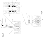
- FIG. 1 a section through a jaw bone 7 is shown, in which a gap 19 is arranged between two teeth 17, in which the gum 18 is interrupted.
- the bone has a porous structure with hollow spaces or cavities 11, particularly below the cortex (in the so-called trabecular or spongy area).
- An implant is to be inserted into such a gap 19.
- such a bone has a porosity in the range of 30-90% in the trabecular or spongy area, which means that the structure that actually supports the bone and is therefore suitable for a support may only make up a small fraction of the volume.
- the procedure is such that in a first step, which is shown schematically in Figure 2 is shown, the actual recess for the implant is prepared with the aid of a drill 20.
- the drill 20 used in this embodiment has on one side a fastening flange for the drive (drive not shown), and on the other side the actual drilling section that creates the drill hole with the known grooves 22 of the actual drill.
- This specific drill has a taper at the tip, i.e. an area with a smaller diameter than the actual drilling area, this taper leads to a tapered bottom area in the resulting recess, in which the diameter is slightly smaller than in the area of the recess further up.
- it is a drill as shown in the WO 2004/080325 described.
- the drill is driven into the bone 7 while rotating along its axis, as indicated by the arrow 24, and the actual recess 8 is thereby formed. Due to the formation of this recess 8 in porous bone, cavities 11 in the peripheral area of this recess, which border on the recess, are to a certain extent exposed and opened.
- this recess 8 is now so-called ameliorated, i.e. it is either prepared for the attachment of an implant in such a recess or simply sealed with regard to the exposed cavities 11.
- the proposed device in this case is prepared in such a way that in the device 1, which is provided with an element for generating ultrasound via a handle and on which a sleeve 4 (cylindrical tube section with a central recess 26) is arranged via an upper fastening 25, a guide pin 3, which has an amelioration sleeve 6 at its lower end which encloses the guide pin all the way around, is pushed into the said recess 26 of the sleeve 4.
- a guide pin 3 with amelioration sleeves 6 to be presented in a holder 32 in different designs (e.g. different thicknesses of amelioration sleeves).
- the material of the amelioration sleeve is selected such that it can be liquefied by applying mechanical energy, in particular ultrasonic vibrations.
- the cuff 4 has at its distal end (i.e. at the end facing away from the handle 2) a circumferential edge 10 tapering towards the tip. When the guide pin 3 is inserted, this conical tip 10 engages in an undercut upper region of the amelioration sleeve (designated with the reference number 43).
- either the guide pin and amelioration sleeve can form a single unit, as shown here, but it is also possible that the cuff, guide rod and amelioration sleeve form a single-use unit. It is also possible that the cuff and amelioration sleeve, or other combinations of elements, form a single-use unit. These units can be presented in a sterile package.
- the material used for the amelioration sleeve can be, for example, a resorbable polymer material of the Resomer type, as available from Boehringer Ingelheim (DE). It can be based on homopolymers of lactic acid (polylactide) or on copolymers of lactic and glycolic acid, and it can also preferably be designed to ensure a controlled release of pharmaceutical active substances (for example, generally active substances to improve healing, such as to promote bone growth, to prevent inflammation, etc.) which are incorporated into this material or applied to it.
- pharmaceutical active substances for example, generally active substances to improve healing, such as to promote bone growth, to prevent inflammation, etc.
- the amelioration sleeve 6 is preferably not arranged at the very tip of the guide tip but is offset slightly to the rear, and the guide pin has an outer diameter which essentially corresponds to the diameter of the taper 9 in the bottom area.
- the device 1 prepared in this way is then, as shown in Figure 4 is shown, inserted into the pre-drilled recess 8.
- the outer diameter of the sleeve 4 is essentially identical to the outer diameter D of the amelioration sleeve, and this outer diameter is essentially the same as or at most insignificantly smaller than the inner diameter of the recess created by the drill.
- the outer diameter of the sleeve it is also possible for the outer diameter of the sleeve to be slightly larger than the inner diameter of the recess, so that an additional widening of the recess occurs when the process is carried out.
- Amelioration sleeve 6 and cuff 4 are essentially completely inserted into the recess and in particular the foremost tip also penetrates of the guide pin into the tapered base area 9 and the front area of the device also completely fills the recesses in the radial direction. This automatically results in optimal centering or positioning of the device in the recess. The device is therefore essentially completely pushed into the recess in accordance with the direction of displacement 13 without the application of ultrasound.
- the device for generating ultrasound can be, for example, a device from Branson Ultrasonics SA, CH, type E-150 with an operating frequency of 20 kHz and an amplitude of 40 ⁇ m at the tip of the sonotrode with an energy of 150 W.
- the mechanical energy can be introduced via the sleeve; this is preferred, but it is also possible to introduce the energy via the guide pin, or both the sleeve and the guide pin.
- the material of the amelioration sleeve gradually liquefies and at the same time, by pressing the handle 2, the sleeve 4 is pushed further and further onto the guide pin.
- the liquefied material is now introduced in a very targeted manner over the circumference, successively from top to bottom, into the cavities 11 exposed by the recess.
- the liquefied material is therefore introduced into these cavities 11 in a targeted manner in a radial direction around the circumference, as far as they have been exposed by drilling, and the usually disadvantageous downward displacement to the bottom of the recess does not occur (which is usually problematic due to the fact that bone material very often becomes increasingly porous with increasing depth).
- the recess is not actually lined with the liquefied material, but only the undesirable cavities adjacent to the recess are filled to a certain extent. Those areas in which the bone already forms a clean boundary of the recess remain essentially uncovered by liquefiable material.
- the radial component as shown schematically by the arrows 28, can be adjusted by adjusting the angle of the edge 10.
- the sleeve does not necessarily have to be pushed on as far as it will go and it is also possible to stop the process somewhat earlier if material of the amelioration sleeve is not to remain displaced in the radial direction at the bottom.
- the tool can then be used as shown in Figure 7 shown, either with the ultrasound switched on or switched off, can be removed from the recess again and the recess is now ameliorated in accordance with the invention, as shown by the reference number 29.
- This means that the peripheral surface 33 of the ameliorated recess 29 is limited by the liquefiable material at least everywhere where cavities were adjacent. The liquefiable material naturally solidifies again after the ultrasound input has been switched off.
- Either the recess thus ameliorated can be left in a sealed state, if this is the aim of the operation, or, as is usually the case, the actual implant can now be attached to the recess.
- This step is in Figure 8 shown for a situation in which a device 31 for screwing in the implant is pressed down with a finger 34 and driven with a torque wrench 35.
- the actual assembly device 36 is attached to the inside of the implant 30 and then removed again after assembly.
- the implant can also be inserted with the handpiece (mechanically). In this case, the sonotrode cannot normally be attached as well.
- the proposed method can generally be used on a human tissue part or a human bone, equally on an animal bone or generally on a porous material (e.g. wood).
- a porous material e.g. wood
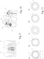
- FIG 10 An application of the proposed method is shown in connection with spinal bones 39.
- an ameliorated recess 40 (created in an analogous process as in the Figures 1 to 7 shown) a screw 38 is used instead of a dental implant.
- a screw 38 also has a very high primary stability, such a screw can be used, for example, to attach a relative fixation 41.
- Figure 11 It will be shown how differently the amelioration sleeve or the guide pin and the cuff can be adjusted according to the needs.
- the normal situation will be the one shown in figure 11a ) is shown.
- the amelioration sleeve shown in a section perpendicular to the axis of the guide pin as AA in Figure 3 shown, has an external diameter D and a central recess with an internal diameter d.
- D an external diameter
- d a relatively thin amelioration sleeve, which means that little liquefiable material is made available.
- the guide pin 3 with an external diameter d is arranged in this amelioration sleeve.
- a thinner guide pin 3 and an amelioration sleeve with a greater wall thickness can be used, as indicated by the dashed line 42.
- FIGs b) - e Alternative designs of the cross-sectional areas of the guide pin 3 and the amelioration sleeve 6 are shown in Figures b) - e).
- the guide pin it is possible for the guide pin to have a square cross-section, for example, as shown in Figure 11b ). It can be advantageous if the corners of the square extend almost to the periphery of the amelioration sleeve, but the square can also have a smaller cross-sectional area. This is the case for a hexagonal cross-section in Figure 11 c) and for a thinner amelioration sleeve and for a symmetrical octagonal cross-section in Figure 11d ).
- the wall thickness of the sleeve 4 should be at least in the range of 0.5-0.8 mm.
- the porosity of the wall of the recess is not particularly pronounced and an amelioration sleeve with a wall thickness of 0.5-0.8 mm would introduce too much material.
- the sleeve 4 can still optimally introduce the material of the amelioration sleeve radially into the wall of the recess in such an amelioration sleeve 6, the sleeve 4 is designed at its distal end in a tapered cylindrical region 46 with a smaller outer diameter.
- the radial offset of this step at the distal end of the sleeve 4 essentially corresponds to the wall thickness of the amelioration sleeve in the region 44.
- the tapered cylindrical portion 46 may be tapered at its distal end, but may also, as in Figure 12 shown, be designed as a rectangular step.
- the tapered cylindrical region 46 engages with the tip in the cavity 45 of the amelioration sleeve 6.
- the proximal end of the amelioration sleeve thus abuts against the inclined flank 48.
- the amelioration sleeve 6 essentially only liquefies in the area of the conical transition 48. Due to the inclined flank in this area 48, the liquefied material is selectively liquefied exclusively in this area and is introduced radially outwards into the peripheral area of the recess and the porosity present there.
- the low wall thickness of area 44 is also generally unproblematic; despite the low wall thickness there, the amelioration sleeve has hardly any tendency to buckle under the longitudinal pressure, for example into the cavity 45.
- the process is shifted to the left, only the thin wall area 44 liquefies in zone 48 and the liquefied material is carried radially outwards in zone 48 until the tip 47 hits the flange 43.
- the process can either be stopped here or further liquefaction takes place, now in the base area with a little more material from the amelioration sleeve.
- the area 47 can also be conical, as already mentioned above.
- the cuff 4 is now only in the front cylindrical region 46 is formed with a small wall thickness, and this region 46 is also essentially only used for guidance, while in the region arranged behind it, where the greater forces are applied, a greater wall thickness can be used without this also requiring a corresponding wall thickness of the amelioration sleeve 6.
- the foremost cylindrical portion 46 has a length of approximately 0.1-5mm, preferably 0.1-1mm or 0.2-0.5mm in the axial direction, preferably a length of 0.1-0.25mm.
- the outer diameter of the sleeve 4 is slightly larger than the original inner diameter of the recess.
- the recess in the base area 9 is again tapered, the guide pin 3 extends into this base area with its distal end.
- the inner diameter of the recess further to the right in Figure 13 above this base area corresponds essentially to the outer diameter of the amelioration sleeve 6, i.e. pin 3 and amelioration sleeve 6 can be pushed into the recess essentially without resistance.
- the sleeve 4 on the other hand, has an outer diameter which is slightly larger than the inner diameter of the recess (the diameter is, for example, 0.1-0.2 mm larger than the inner diameter). If the sleeve 4 is now pressed into the recess, this leads to a forced widening of the recess, as is shown schematically by the already expanded section 49.
- Such a forced expansion by the sleeve 4 can be advantageous, for example, if the recess does not have the desired shape and/or the desired diameter and is to be cleaned up to a certain extent by this process by the sleeve 4.
Landscapes
- Health & Medical Sciences (AREA)
- Orthopedic Medicine & Surgery (AREA)
- Life Sciences & Earth Sciences (AREA)
- Surgery (AREA)
- Engineering & Computer Science (AREA)
- Veterinary Medicine (AREA)
- Public Health (AREA)
- General Health & Medical Sciences (AREA)
- Animal Behavior & Ethology (AREA)
- Molecular Biology (AREA)
- Medical Informatics (AREA)
- Heart & Thoracic Surgery (AREA)
- Biomedical Technology (AREA)
- Nuclear Medicine, Radiotherapy & Molecular Imaging (AREA)
- Oral & Maxillofacial Surgery (AREA)
- Ceramic Engineering (AREA)
- Neurology (AREA)
- Dentistry (AREA)
- Epidemiology (AREA)
- Mechanical Engineering (AREA)
- Surgical Instruments (AREA)
- Prostheses (AREA)
- Media Introduction/Drainage Providing Device (AREA)
Description
- Die vorliegende Erfindung betrifft eine Vorrichtung zur Amelioration einer Ausnehmung, insbesondere einer Ausnehmung in einem porösen oder löchrigen respektive durch die Ausnehmung freigelegte Hohlräume aufweisenden Material wie beispielsweise Holz, technisches Material, einem tierischen oder menschlichen Knochen. Des weiteren betrifft sie Verfahren zur Amelioration von Ausnehmungen in porösen oder löchrigen respektive durch die Ausnehmung freigelegte Hohlräume aufweisenden Materialien wie beispielsweise tierischem oder menschlichem Knochen, insbesondere in Kieferknochen oder Wirbelsäulenknochen.
- Insbesondere aus dem Bereich der Befestigung von Implantaten in Ausnehmungen im tierischen oder menschlichen Körper wie bspw. in Bohrungen in Knochen ist es bekannt, Implantate, welche bspw. mit einem selbstschneidenden Gewinde ausgestattet sind, unter Kraftanwendung in solche Ausnehmungen einzudrehen und anschliessend darauf zu warten, dass das Implantat in den Knochen einwächst.
- Ebenfalls ist es bekannt, dass insbesondere bei Ausnehmungen, welche in besonders porösen Knochenabschnitten vorgesehen werden, die so genannte Primärstabilität, das heisst die Stabilität des Implantates in der Ausnehmung unmittelbar nach dem Eindrehen, das heisst bevor das eigentliche Einwachsen abgeschlossen ist, ungenügend sein kann.
- Um solche Probleme zu lösen, wurde bereits vorgeschlagen (vgl. bspw. die
EP 1 363 543 ) das Implantat wenigstens teilweise oder sogar vollständig aus einem durch mechanische Energie verflüssigbaren Material herzustellen. Das verflüssigbare Material kann nach Einbringen des Implantates in den Gewebeteil durch mechanische Schwingungen verflüssigt werden und so wird eine formschlüssige Verbindung zwischen Knochen und Implantat, vermittelt durch das verflüssigte und anschliessend wieder verfestigte Material, hergestellt. Nachteilig an derartigen Lösungen ist die Tatsache, dass ganz spezifische Implantate erforderlich sind, um derartige Verfahren durchführen zu können. Des Weiteren ist nachteilig, dass das verflüssigbare Material nicht genügend gezielt in die gewünschten Bereiche eingebracht werden kann und häufig bspw. in am Boden der Ausnehmungen angeordneten grossen Ausnehmungen verschwindet ohne am Ende zur eigentlichen Primärstabilisierung beizutragen. Grundsätzlich ist das Konzept, Ausnehmungen in einem menschlichen Körper unter Zuhilfenahme eines verflüssigbaren Materials, insbesondere im Dentalbereich, auszufüllen, bereits seit langem bekannt. So beschreibt dieUS 3,919,775 ein Verfahren zum Ausfüllen und Vorbereiten von Öffnungen unter Zuhilfenahme eines verflüssigbaren Materials, welches zunächst in die Öffnung eingepresst wird, und anschliessend unter Zuhilfenahme einer Sonotrode, das heisst einer Vorrichtung, mit welcher mechanische Energie in Form von Ultraschall eingetragen werden kann, verflüssigt wird. Das verflüssigte Material fliesst anschliessend in Kavitäten und Hohlräume, welche an die Ausnehmung angrenzen und verschliesst diese. Auch in anderen Gebieten, wo technische Materialien wie z.B. Holz, Kunststoffe, Schaumstoffe etc. bearbeitet werden, sind solche Techniken im weitesten Sinne bekannt. - Dokumente
WO 2008034278 undWO 2008034277 offenbaren eine Vorrichtung zur Amelioration einer Ausnehmung, umfassend eine Sonotrode, eine Ameliorationshülse aus einem mit mechanischer Energie verflüssigbaren Material und einen Führungsstift sowie eine zylindrische Manschette mit einer zentralen Ausnehmung zur Aufnahme des Führungsstiftes. Der Führungsstift wird von der Ameliorationshülse umschlossen, wobei die Manschette bei Anlegen von mechanischer Energie relativ zum Führungsstift in Richtung zum Boden der Ausnehmung unter Verflüssigung und seitlicher und/oder longitudinaler Verdrängung des Materials der Ameliorationshülse verschiebbar ist. - Die Erfindung ist in den Ansprüchen definiert.
- Der Erfindung liegt demnach die Aufgabe zugrunde, eine Vorrichtung zur Amelioration einer Ausnehmung zur Verfügung zu stellen. Die Vorrichtung soll dabei insbesondere dazu geeignet sein, Ausnehmungen in einem porösen oder mit an die Ausnehmung grenzenden Löchern respektive Hohlräumen ausgestaltetem Material für weitere Bearbeitungen vorzubereiten. Insbesondere geht es um die Vorbereitung von Ausnehmungen respektive (Sack-)Löchern oder Durchgangsöffnungen in Holz oder holzartigen Werkstoffen, porösen Kunststoffen, oder Schaumstoffmaterial, insbesondere ein Polymerschaum, ein Verbundschaum und/oder ein Metallschaum, aber auch im tierischen oder menschlichen Knochen, so beispielsweise die Vorbereitung von derartigen Ausnehmungen zur anschliessenden Befestigung von Befestigungsmitteln oder Implantaten (ebenfalls eingeschlossen ist die Befestigung von Stiften oder Sehnen oder die Verankerung von künstlichen Gelenken wie beispielsweise Hüfte, Finger, Schulter etc.), so dass im Fall von nicht-tierischen respektive nicht-menschlichen Materialien die zusätzliche Verwendung von Klebstoffen vermieden werden kann und im Fall von Knochenmaterial eine schnelle Primärstabilisation des Implantates gewährleistet ist. Auf der anderen Seite soll die Amelioration auch dazu geeignet sein, eine derartige Ausnehmung gewissermassen zu versiegeln, wie dies beispielsweise in der Endodontie im Zusammenhang mit der Verschliessung von Wurzelkanälen interessant sein kann.
- Die Lösung dieser Aufgabe wird dadurch erreicht, dass eine solche Vorrichtung, welche ein Element zur Erzeugung oder zur Einkopplung von mechanischer Energie, insbesondere von Vibrationsenergie respektive Schwingungsenergie wie zum Beispiel Ultraschall-Schwingungen aufweist, weiterhin eine zylindrische Manschette mit zylindrischer Mantelfläche mit einem Aussendurchmesser und mit einer zentralen Ausnehmung zur Aufnahme eines Führungsstiftes aufweist. Dabei ist der Führungsstift dazu vorgesehen und insbesondere in der Ausnehmung angeordnet, um vor dem Anlegen von mechanischer Energie, insbesondere von Schwingungen, im wesentlichen bis auf den Boden der Ausnehmung eingeführt zu sein (oder wenigstens im Bereich des Bodens der Ausnehmung beispielsweise in einer Führungsverjüngung gefangen), und so eine optimale Führung des Werkzeugs zu gewährleisten. Dabei wird der Führungsstift im Bereich seines dem Boden der Ausnehmung zugewandten Endes von einer Ameliorationshülse aus einem mit mechanischer Energie, insbesondere mit Schwingungsenergie wie bevorzugtermassen Ultraschall-Schwingungen verflüssigbaren Material umschlossen. Die (kreis-)zylindrische Mantelfläche der Ameliorationshülse weist im wesentlichen den gleichen Aussendurchmesser auf wie die Manschette, und der Führungsstift ist in der zentralen Ausnehmung derart verschieblich aufgenommen, dass die Manschette bei Anlegen von mechanischer Energie wie bevorzugtermassen Ultraschall-Schwingungen relativ zum Führungsstift in Richtung zum Boden der Ausnehmung unter Verflüssigung und seitlicher und/oder longitudinaler Verdrängung des Materials der Ameliorationshülse verschoben werden kann.
- Der Führungsstift ist in der zentralen Ausnehmung bevorzugt so gut wie spielfrei verschieblich aufgenommen, das heißt der Außendurchmesser des Führungsstiftes entspricht im wesentlichen dem Innendurchmesser der zentralen Ausnehmung und ist gerade nur soviel geringer, dass der Führungsstift longitudinal in der Ausnehmung verschoben werden kann. Der Unterschied zwischen dem Außendurchmesser des Führungsstiftes und dem Innendurchmesser der Ausnehmung sollte entsprechend nicht größer sein als 0.001mm oder 0.01mm, obere Grenze ist z.B. bei Anwendungen im Implantatbereich normalerweise 0.1-0.5 mm oder 0.2-0.3mm.
- Einer der Kernpunkte dieser Vorrichtung ist es also, einerseits einen Führungsstift vorzusehen, welcher in die Tiefe der Ausnehmung eingeschoben werden kann und die anschliessende Führung des Werkzeugs gewährleisten kann. Der Führungsstift dient also einerseits einer optimalen Positionierung des Werkzeugs in der Tiefe der Ausnehmung. Der Führungsstift dient aber andererseits auch zur Führung der Manschette, welche gewissermassen im oberen Bereich (bei Beginn des Prozesses) den Führungsstift umschliesst. Bei Beginn des Prozesses ist unterhalb der Manschette ebenfalls den Führungsstift umschliessend die Ameliorationshülse angeordnet. Nach der Erfindung verfügt die Ameliorationshülse über einen Aussendurchmesser, welcher gleich ist (oder gegebenenfalls unwesentlich geringer) als der Aussendurchmesser der Manschette. Typischerweise ist nämlich die Ausnehmung von zylindrischer Form. Dabei muss hervorgehoben werden, dass unter dem Begriff " zylindrische Form" zwar bevorzugtermassen eine kreiszylindrische Form zu verstehen ist (das heisst mit einem kreisrunden Querschnitt senkrecht zur Hauptachse), dass aber darunter auch Formen zu verstehen sind, welche einen ovalen respektive linsenförmigen oder ellipsenförmigen Querschnitt senkrecht zur Hauptachse des Werkzeugs aufweisen. Insbesondere im Bereich der Implantologie gibt es einerseits Ausnehmungen, welche einfach kreisförmig sind und durch die Verwendung eines rotierenden Bohrers hergestellt worden sind, es gibt aber auch zum Beispiel im Falle von dentalen Anwendungen ovale, linsenförmige oder ellipsenförmige Öffnungen (beispielsweise in definierter und aufbereiteter Form erzeugt durch ein Bohren und anschliessendes Raspeln), beispielsweise vorgegeben durch die Form einer Zahnwurzel. Im letzteren Fall, das heisst für ovale, linsenförmige oder ellipsenförmige Öffnungen, ist es also möglich, sowohl die Manschette als auch die Ameliorationshülse in ihrer Aussenform dieser eben dann z.B. oval-zylindrischen Ausnehmung anzupassen. Auch spezifische, beispielsweise auf Zahnwurzeln angepasste abgerundete andere Formen von Querschnitten sind für die Aussenform der Manschette und der Ameliorationshülse möglich.
- Aufgrund der Tatsache, dass die Manschette auf dem Führungsstift verschieblich im Rahmen der Vorrichtung angeordnet ist, kann nun nach Anlegen der mechanischen Energie, z.B. der Ultraschall-Schwingungen, und entsprechender Verflüssigung des Materials der Ameliorationshülse das Material der Letzteren sukzessive von oben nach unten in die an die Ausnehmung grenzenden porösen Bereiche des die Ausnehmung bildenden Materials eingebracht werden. So werden ganz gezielt die Hohlräume, welche eine anschliessende Befestigung einer Schraube oder eines Implantats in der Ausnehmung schmälern könnten, im entscheidenden Bereich insbesondere unmittelbar am Umfang der Ausnehmung mit dem Material der Ameliorationshülse gefüllt, was eine enorme Erhöhung der Primärstabilisation nach sich zieht. Es ist aber nicht notwendigerweise zwingend, dass anschliessend überhaupt ein weiteres Element in eine solche ameliorierte Ausnehmung eingebracht wird, es ist auch möglich, durch das vorgeschlagene Verfahren respektive die vorgeschlagene Vorrichtung die Ausnehmung gewissermassen nur ganz gezielt in ihrem Umfangsbereich gewissermassen zu versiegeln (vergleiche die oben erwähnten Anwendungen im Zusammenhang mit der Endodontie).
- Die Erfindung ist dadurch gekennzeichnet, dass der Aussendurchmesser von Manschette und/oder von Ameliorationshülse im wesentlichen gleich sind, oder Letzterer nur unwesentlich geringer, und dass des weiteren dieser Aussendurchmesser im wesentlichen gleich ist wie der Innendurchmesser der zu ameliorierenden Ausnehmung. Für den Fall eines nicht kreiszylindrischen Querschnittes ist dies so zu verstehen, dass der im wesentlichen gleiche Aussen-Querschnitt bei Manschette und/oder Ameliorationshülse vorliegt und die beiden Elemente relativ zueinander so angeordnet sind, dass ein im wesentlichen glatter das heisst stufenloser Übergang vorliegt. So ist bereits zu Beginn des Prozesses der distale Bereich (das heisst der dem Boden der Ausnehmung zugewandter Bereich) des Werkzeugs sowie auch der gesamte in der Ausnehmung angeordnete dahinterliegende Bereich des Werkzeugs optimal positioniert und geführt. Typischerweise verfügt die Ameliorationshülse über eine Höhe (entlang der Achse der Ausnehmung), welche geringer oder gleich ist wie die Tiefe der Ausnehmung, das heisst beim Beginn des Prozesses verschwindet die Ameliorationshülse vollständig in der Tiefe der Ausnehmung und auch die Manschette dringt teilweise in den oberen Bereich der Ausnehmung bereits ein, oder die Ameliorationshülse schliesst (insbesondere bei der Anwendung in Holz oder anderen porösen Werkstoffen) bündig mit der Oberkante des Materials ab. Typischerweise dringt die Manschette bereits 5-50% in die Ausnehmung ein, bevor der Ultraschall angelegt wird.
- Es ist auch möglich, dass der Außendurchmesser der Manschette etwas größer ist als der Innendurchmesser der zu ameliorierenden Ausnehmung (beispielsweise 0.5-2 mm grösser). In diesem Fall wird beim Einführen der Vorrichtung die zu ameliorierende Ausnehmung durch die Vorrichtung noch etwas ausgeweitet und/oder in die gewünschte Form gebracht. Insbesondere bei technischen Materialien kann dies von Vorteil sein.
- Eine weitere bevorzugte Ausführungsform der vorgeschlagene Vorrichtung ist dadurch gekennzeichnet, dass die zentrale Ausnehmung eine kreiszylindrische Ausnehmung ist, welche koaxial zur zylindrischen Mantelfläche angeordnet ist, dass die Ameliorationshülse eine kreiszylindrische Ausnehmung zur Aufnahme des Führungsstifts aufweist, und dass der Führungsstift eine kreiszylindrische Aussenfläche aufweist, wobei die Innendurchmesser der genannten Ausnehmungen im wesentlichen gleich sind wie der Aussendurchmesser des Führungsstiftes.
- Alternativ sind aber auch andere Querschnittsform in der zentralen Ausnehmung in der Manschette möglich. So ist es beispielsweise möglich, dass die zentrale Ausnehmung eine (gleichschenklige) Dreiecksform, eine quadratische Form, oder generell eine Mehreckform (vorzugsweise mit gleich langen Seiten) aufweist, wobei die Spitzen einer solchen Querschnittsform auch bis zum Aussendurchmesser der Manschette reichen können. So kann beispielsweise gezielt in bestimmte Richtungen mehr Material vorgesehen werden. Die Querschnitts-Formen können auch runde verallgemeinerte Formen sein, sie können konkav oder konvex ausgestaltet sein. Entsprechend ist selbstverständlich dann die Querschnittsform des Führungsstiftes analog ausgebildet, wobei generell gilt, dass zwischen den Führungsstift und der Manschette ein möglichst geringer Spalt ausgebildet sein soll, damit in den Spalt zwischen diesen beiden Materialien kein verflüssigtes Material eindringen kann. Es ist aber möglich, in diesem Spalt ganz gezielt gewissermassen Kanäle vorzusehen, die ein gezieltes Abfliessen von Material bei zu hohem Druck (beispielsweise wenn keine Hohlräume zur Verdrängung des Materials vorliegen) ermöglichen. Solche Kanäle können beispielsweise das verflüssigtes Material nach oben, das heisst in Richtung aus der Ausnehmung hinaus, abführen.
- Um eine optimale Verdrängung des Materials der Ameliorationshülse nicht nur nach unten sondern radial nach aussen in die Umfangsbereich mit der Ausnehmung zu verteilen, kann es von Vorteil sein, wenn die Manschette an ihrem distalen Ende eine zu diesem hin zulaufende bevorzugt umlaufende distale Kante aufweist, wobei vorzugsweise diese Kante gerade und damit konisch oder gekrümmt, insbesondere konkav oder konvex, ausgebildet ist. Diese zulaufende Kante führt dazu, dass das Material nicht nur eine Verdrängungskomponente in Richtung des Bodens der Ausnehmung erfährt, sondern auch eine radiale Komponente. Über den Neigungswinkel dieser zulaufenden Kante kann u.a. eingestellt werden, wie stark das Material in radialer Richtung (das heisst senkrecht zur zentralen Achse der Ausnehmung respektive senkrecht zur Hauptachse des Werkzeugs) respektive longitudinaler Richtung (das heisst in Richtung zum Boden der Ausnehmung und damit parallel zur zentralen Achse der Ausnehmung respektive parallel zur Hauptachse des Werkzeugs) verdrängt werden kann. Soll beispielsweise möglichst wenig zum Boden der Ausnehmung verdrängt werden (weil beispielsweise in diesem Bereich bekanntermassen grosse Hohlräume vorhanden sind, deren Ausfüllung weder erwünscht noch notwendig ist), so kann ein sehr spitzer Winkel gewählt werden (beispielsweise < 45°, wobei der Winkel definiert ist als der Winkel zwischen der zentralen Hauptachse der Manschette und der Neigungsfläche der Kante) so dass eine grosse radiale Komponente entsteht. Soll auf der anderen Seite möglichst viel Material zum Boden der Ausnehmung verteilt werden, so kann ein Winkel grösser als 45° gewählt werden. Auf jeden Fall sollte dieser Winkel bevorzugtermassen kleiner oder gleich 90° sein, bei grösseren Winkeln wird das Material (was aber ebenfalls gewünscht sein kann) ausschliesslich zum Boden geschoben.
- Die Manschette kann am distalen Ende auch gestuft ausgebildet sein. Da die Manschette vorzugsweise direkt an die Sonotrode angeschlossen ist, ist es von Vorteil, wenn die Wandstärke der Manschette nicht zu gering ist. Typischerweise sollte die Wandstärke der Manschette für typische Anwendungen im medizinischen Bereich im Bereich von 0.3-1 mm, vorzugsweise im Bereich von 0.5-0.8 mm sein. Auf der anderen Seite kann es für bestimmte Anwendungen von Vorteil sein, wenn die Ameliorationshülse eine geringere Wandstärke aufweist, damit nicht zu viel Material eingetragen wird. Die Ameliorationshülse hat bevorzugtermassen eine Wandstärke im Bereich von 0.1-1 mm, und kann beispielsweise auch nur halb so dick sein wie die Wandstärke der Manschette. Um diesen Verhältnissen Rechnung zu tragen, ist es möglich, die Ameliorationshülse auf deren Innenseite hinter deren distalem Ende auszunehmen, vorzugsweise umlaufend auszunehmen. Entsprechend resultiert eine geringere Wandstärke der Ameliorationshülse, und es entsteht zwischen Führungsstift und Ameliorationshülse ein Hohlraum.
- Es ist bei solchen dünnen Ameliorationshülsen dann eben vorzugsweise auch möglich, die Manschette an deren distalem Ende gestuft auszubilden, wobei am distalen Ende der Manschette ein zylindrischer Bereich mit geringerem Außendurchmesser vorgesehen ist, welcher in diesen Hohlraum der Ameliorationshülse respektive den Zwischenraum zwischen Ameliorationshülse und Führungsstift eingreift und umlaufend von der Ameliorationshülse mit dünnerer Wandstärke umschlossen ist. Dieser Bereich mit geringerem Außendurchmesser geht bevorzugtermassen in einer geneigten Flanke über in einen Bereich mit dem eigentlichen Außendurchmesser der Manschette. In diesem geneigten Bereich erfolgt die Verflüssigung der Ameliorationshülse und der Transport des verflüssigten Materials radial nach außen.
- Erfindungsgemäss kann der Führungsstift bei der vorgeschlagenen Vorrichtung bis zu einer Anschlagsposition in die Manschette eingeschoben werden, damit eine definierte Endposition für das mit der Vorrichtung geplante Verfahren vorhanden ist. Dabei schliesst bei dieser Anschlagsposition der Führungsstift bündig mit dem distalen Ende der Manschette ab.
- Zur guten Positionierung des Führungsstiftes im Bereich des Bodens der Ausnehmung kann es von Vorteil sein, wenn der Führungsstift an seinem distalen Ende kegelförmig zulaufend und bevorzugt mit einer scharfen Spitze ausgebildet ist oder es kann von Vorteil sein, wenn der Führungsstift an diesem Ende abgerundet ausgestaltet ist. Die Rundung respektive generell die Gestaltung der Spitze kann dabei angepasst sein an den typischerweise zur Vorbereitung der Ausnehmung verwendeten Bohrer. Wird beispielsweise ein Bohrer verwendet, welcher einen Versatz oder eine Verjüngung zur Führung an der Spitze aufweist, und der Führungsstift weist vorzugsweise einen an den Durchmesser dieser Verjüngung angepassten Aussendurchmesser auf.
- Die Vorrichtung ist bevorzugtermassen dadurch gekennzeichnet, dass der Aussendurchmesser der Manschette im Bereich von 1-50mm oder sogar 1-80 mm, bevorzugt im Bereich von 2-10 mm beträgt. Weiterhin wird bevorzugt, dass der Aussendurchmesser des Führungsstiftes 0.1 - 20 mm, bevorzugt 0.5-10 mm, insbesondere bevorzugt 1- 5 mm, geringer ist, und dass die Ameliorationshülse eine Dicke aufweist, so dass deren Aussendurchmesser gleich ist wie der Aussendurchmesser der Manschette.
- Typischerweise erzeugt das Element (die eigentliche Sonotrode) mechanische Energie in Form von Schwingungsenergie mit einer Frequenz im Bereich von 1 kHz-10 GHz. Bevorzugt wird dabei, dass die Schwingung Energie als Ultraschall-Schwingungen im Frequenzbereich von 10 kHz bis 10 GHz eingetragen wird. Bevorzugt wird ein Frequenzbereich von 10 kHz - 100 MHz, insbesondere bevorzugt ein Bereich von 40 kHz- 100 MHz. Normalerweise werden Ultraschall-Schwingungen im Bereich von 20-150 kHz, bevorzugtermassen im Bereich von 25-50 kHz eingesetzt. Diese Schwingungen können in longitudinaler (das heisst entlang der Achse der Ausnehmung), transversaler (das heisst radial zur Achse der Ausnehmung) oder rotativer (das heisst um die Achse der Ausnehmung) Richtung, oder einer Kombination resp. Linearkombination dieser Richtungen auf Manschette und/oder Führungsstift und damit mittelbar auf die Ameliorationshülse übertragen werden. Vorzugsweise werden die Schwingungen in longitudinaler Richtung angelegt, wobei dann, wenn z.B. am distalen Ende der Manschette eine geneigte Flanke vorhanden ist, diese longitudinale Schwingung einen gezielten Transport des verflüssigten Materials in radialer Richtung ermöglicht. Generell bevorzugtermassen ist die Manschette an der Sonotrode befestigt und der Führungsstift kann in dieser verschoben werden. Alternativ ist es möglich, dass der Führungsstift an der Sonotrode befestigt ist und die Manschette verschoben werden kann.
- Eine bevorzugte Ausführungsform der Vorrichtung ist dadurch gekennzeichnet, dass es sich bei der Ausnehmung um eine Ausnehmung in einem wenigstens teilweise porösen (menschlichen) Knochenabschnitt handelt, insbesondere in einem Kieferknochen oder einem Wirbelsäulenknochen, und dass bevorzugtermassen die Ausnehmung wenigstens teilweise durch eine Vorbohrung erzeugt ist.
- Bevorzugtermassen besteht die Ameliorationshülse aus einem durch die genannte mechanische Energie, insbesondere durch Schwingungsenergie verflüssigbaren Material ausgewählt aus der Gruppe: thermoplastischer biokompatibler Polymere wie beispielsweise Polyolefine (z. B. PP, LDPE, HDPE, UHMWPE), Polyoxymethylen (POM), Polyaryletherketone (z.B. PAEK, PEEK, PEKK), Polycarbonate (PC), Polyacrylate (z.B. PMMA), Polyamide (PA), Polyester (z.B. PET, PBT), Polysulfone und Polyethersulfone (z.B. PSU, PES) und/oder biodegradierbare respektive resorbierbare Polymere wie beispielsweise Poly-(L-lactide) (PLLA), poly-(D,L-lactide) (PDLLA), und derer Stereocopolymere mit variierendem Verhältnis des L und D,L Anteils, Polyglycolide (PGA) und Copolymere wie Polyglycolide-cotrimethylencarbonat (PGA-co-TMC), Poly-(D,L-lactide-co-glycolide) (PDLLA-co-PGA), und Poly-(L-lactide-co-glycolide) (PLLA-co-PGA), Poly(e-caprolactone), Polydioxanone, Trimethylene carbonate (TMC), Polyorthoester (POE) und andere Polyanhydride, resorbierbare Polymere welche aus natürlich Rohstoffen hergestellt werden wie beispielsweise modifizierte Polysaccharide (Zellulose, Chitin, Dextran, Stärke), oder eine Kombination respektive einer Mischung dieser Materialien. Grundsätzlich können in diesem Material oder als Schicht auf diesem Material aufgetragen auch eine oder mehrere pharmazeutische Wirksubstanzen vorgesehen werden, dies beispielsweise generell Wirksubstanzen zur Verbesserung der Einheilung, wie beispielsweise zur Förderung des Knochenwachstums, zur Verhinderung von Entzündungen etc.. Das Material kann dabei spezifisch dazu ausgelegt sein, diese pharmazeutischen Wirksubstanzen kontrolliert, das heisst über einen kontrollierten Zeitraum in einer kontrollierten Dosis, freizusetzen.
- Die Ameliorationshülse kann materialseitig geschlossen, aber auch durchbrochen in jeweils verschiedenen Formen wie beispielsweise gelocht oder geschlitzt ausgeführt sein, um die einzubringende Materialmenge, wenn erforderlich, den anatomischen Gegebenheiten respektive der Materialdichte respektive spezifisch der Knochendichte/qualität und damit den an die Ausnehmung angrenzenden Hohlräumen anpassen zu können
- Ebenso betrifft die vorliegende Erfindung ein nicht in vivo Verfahren zum Betrieb einer Vorrichtung, wie sie oben beschrieben worden ist. Das Verfahren ist bevorzugtermassen dadurch gekennzeichnet, dass die Vorrichtung mit aufgesetztem Führungsstift und aufgesetzter Ameliorationshülse in eine, ggf. zuvor ausgebohrte (und ev. zusätzlich zu einer z.B. ovalen Form ausgeraspelte), Ausnehmung mit einem Innendurchmesser, welcher im wesentlichen dem Aussendurchmesser von Manschette respektive Ameliorationshülse entspricht (vorzugsweise beträgt der Abstand zwischen Ausnehmungen und Manschette respektive Ameliorationshülse nicht mehr als 1 mm, vorzugsweise nicht mehr als 0.5 mm, insbesondere vorzugsweise nicht mehr als 0.1 mm), derart eingeschoben wird, bis vorzugsweise der Führungsstift auf dem Boden der Ausnehmung anschlägt, und/oder in eine am Boden der Ausnehmung angeordnete Führungsverjüngung eingreift, und anschliessend unter gleichzeitiger Verflüssigung der Ameliorationshülse durch angelegte mechanische Energie wie beispielsweise durch angelegten Ultraschall und Hineinschieben der Manschette mit deren distalem Ende in die Ausnehmung hinein verflüssigtes Material in insbesondere laterale Hohlräume angrenzend an die Ausnehmung eingetragen wird. Dies gilt gleichermassen für Anwendungen in Materialien wie beispielsweise Holz oder Schaumstoffmaterial, insbesondere Polymerschaum, Verbundschaum und/oder Metallschaum etc..
- Zu guter letzt betrifft die vorliegende Erfindung ein nicht in vivo Verfahren zur Amelioration einer Ausnehmung in einem porösen Material wie beispielsweise Holz, unter Verwendung einer Vorrichtung, wie sie oben geschildert wurde. Das nicht in vivo Verfahren ist bevorzugtermassen dadurch gekennzeichnet, dass die Vorrichtung mit aufgesetztem Führungsstift und aufgesetzter Ameliorationshülse in die ggf. zuvor ausgebohrte (und gegebenenfalls zusätzlich in einem zusätzlichen oder gleichzeitigen Arbeitsschritt in eine nicht-kreisrunde Querschnittsform gebrachte) Ausnehmung mit einem Innendurchmesser, welche im wesentlichen dem Aussendurchmesser von Manschette respektive Ameliorationshülse entspricht, derart eingeschoben wird, bis vorzugsweise der Führungsstift auf dem Boden der Ausnehmung anschlägt, und/oder in einer am Boden der Ausnehmung angeordnete Führungsverjüngung der Ausnehmung eingreift, und anschliessend unter gleichzeitiger Verflüssigung der Ameliorationshülse durch angelegte mechanische Energie, bevorzugt durch angelegten Ultraschall und hineinschieben der Manschette mit deren distalem Ende in die Ausnehmung hinein verflüssigtes Material in insbesondere laterale Hohlräume angrenzend an die Ausnehmung eingetragen wird, wobei bevorzugtermassen anschliessend in die ameliorierte Ausnehmung ein Befestigungsmittel, ein Gelenk, ein Gelenkabschnitt, oder eine Schraube etc., ggf. teilweise selbstschneidend eingedreht wird.
- Weitere bevorzugte Ausführungsformen der Erfindung sind in den abhängigen Ansprüchen beschrieben.
- Die Erfindung soll nachfolgend anhand von Ausführungsbeispielen im Zusammenhang mit der Zeichnung näher erläutert werden. Es zeigen:
- Fig. 1
- Schnittdarstellung eines Bereiches eine Lücke in der Zahnreihe, in welchem ein Implantat gesetzt werden soll;
- Fig. 2
- Schnittdarstellung nach
Fig. 1 , Phase des Bohrens / Ausbohrens der Aufnahmeausnehmung für das Implantat; - Fig. 3
- Schnittdarstellung nach
Fig. 1 , Phase der Auswahl und des Aufsetzens/der Aufnahme der Ameliorationshülse mit Führungsstift auf Sonotrode resp. In Manschette; - Fig. 4
- Schnittdarstellung nach
Fig. 1 , Phase des Einsetzens der Ameliorationshülse in die Bohrung, Situation unmittelbar vor dem Beginn der Anregung mit der Sonotrode; - Fig. 5
- Schnittdarstellung nach
Fig. 1 , Phase der Anregung mit der Sonotrode (Zwischenstand, mit Detailausschnitt der Spitzenregion); - Fig. 6
- Schnittdarstellung nach
Fig. 1 , Phase nach der Anregung mit der Sonotrode (Endzustand, mit Detailausschnitt der Spitzenregion); - Fig. 7
- Schnittdarstellung nach
Fig. 1 , Zustand nach der Anregung mit der Sonotrode und nach deren Entnahme aus der ameliorierten Bohrung (mit Detailausschnitt der Spitzenregion); - Fig. 8
- Einschrauben des Implantats, manuell mit Abstützung durch Finger;
- Fig. 9
- eingesetztes Implantat;
- Fig. 10
- schematische Ansicht eines in eine analog ameliorierte Öffnung in einem Wirbelsäulenbereich eingesetztes Implantat/Schraube;
- Fig. 11a) - e)
- unterschiedliche Querschnittsgestaltungen des Führungsstiftes in Schnittdarstellungen senkrecht zur zentralen Achse der Manschette resp. der Ameliorationshülse auf einer Höhe, in welcher die Ameliorationshülse geschnitten wird;
- Fig. 12
- einen axialen Schnitt durch eine Vorrichtung mit einer Ameliorationshülse mit dünner Wandstärke;
- Fig. 13
- einen axialen Schnitt durch eine Vorrichtung die in einer Ausnehmung eingeführt ist, welche einen geringeren Innendurchmesser aufweist als der Außendurchmesser der Manschette.
- Die oben im allgemeinen beschriebene Erfindung soll nun im Zusammenhang mit den Figuren im Detail weiter erläutert werden. Die nun anfolgende Beschreibung soll zur Stützung der Ansprüche hinzugezogen werden, nicht aber zu deren Einschränkung verwendet werden.
- Im Sinne eines ersten Ausführungsbeispiels der vorliegenden Erfindung soll beschrieben werden, wie eine Vorrichtung, wie sie oben beschrieben wurde, zur Befestigung eines Dentalimplantates eingesetzt werden kann. Das analoge Verfahren unter Verwendung einer analogen Vorrichtung kann aber, wie bereits eingangs erläutert, gleichermassen für Ausnehmungen in beispielsweise Holz oder anderen porösen Werkstoffen wie Schaumstoffmaterial, insbesondere Polymerschaum, Verbundschaum und/oder Metallschaum etc. eingesetzt werden.
- So ist in
Figur 1 ein Schnitt durch einen Kieferknochen 7 angegeben, bei welchem zwischen zwei Zähnen 17 eine Lücke 19 angeordnet ist, bei welcher auch das Zahnfleisch 18 unterbrochen ist. Der Knochen weist wie üblich insbesondere unterhalb der Kortikalis (im so genannten trabekulären respektive spongösen-Bereich) eine poröse Struktur mit Hohlräumen resp. Kavitäten 11 auf. In eine solche Lücke 19 soll ein Implantat eingesetzt werden. Typischerweise weist ein derartiger Knochen im trabekulären respektive spongösen Bereich eine Porosität im Bereich von 30-90% auf, das heisst die eigentlich tragende und damit für eine Halterung geeignete Struktur macht unter Umständen nur einen geringen Bruchteil des Volumens aus. - Entsprechend wird so vorgegangen, dass in einem ersten Schritt, der schematisch in
Figur 2 dargestellt ist, unter Zuhilfenahme eines Bohrers 20 die eigentliche Ausnehmung für das Implantat vorbereitet wird. Der in diesem Ausführungsbeispiel verwendete Bohrer 20 verfügt auf der einen Seite über einen Befestigungsflansch für den Antrieb (Antrieb nicht dargestellt), und auf der anderen Seite über den eigentlichen das Bohrloch erzeugenden Bohrabschnitt mit den bekannten Zügen 22 des eigentlichen Bohrers. Dieser spezifische Bohrer verfügt über eine Verjüngung an der Spitze, das heisst über einen Bereich mit einem geringeren Durchmesser als der eigentliche Bohrbereich, diese Verjüngung führt in der resultierenden Ausnehmung zu einem verjüngten Bodenbereich, in welchem der Durchmesser etwas geringer ist als im weiter oberhalb liegenden Bereich der Ausnehmung. Es handelt sich beispielsweise um einen Bohrer, wie er in derWO 2004/080325 beschrieben wird. - Der Bohrer wird, wie dies durch den Pfeil 24 angegeben ist, unter Drehung entlang seiner Achse in den Knochen 7 eingetrieben und es bildet sich dabei die eigentliche Ausnehmung 8. Aufgrund der Ausbildung dieser Ausnehmung 8 in porösen Knochen werden im peripheren Bereich dieser Ausnehmung Hohlräume 11, welche an die Ausnehmung angrenzen, gewissermassen freigelegt und geöffnet.
- In einem nächsten Schritt wird nun diese Ausnehmung 8 so genannt amelioriert, das heisst entweder für die Befestigung eines Implantates in einer solchen Ausnehmung vorbereitet oder einfach nur bezüglich der offen liegenden Hohlräume 11 versiegelt.
- Zu diesem Zweck wird die vorgeschlagene Vorrichtung (vgl.
Figur 3 ) in diesem Fall so präpariert, indem bei der Vorrichtung 1, welche über einen Handgriff mit einem Element zur Erzeugung von Ultraschall versehen ist, und an welchem über eine obere Befestigung 25 eine Manschette 4 (zylindrischer Rohrabschnitt mit zentraler Ausnehmung 26) angeordnet ist, ein Führungsstift 3, welcher an seinem unteren Ende über eine Ameliorationshülse 6, welche den Führungsstift umlaufend umschliesst, verfügt, in die genannte Ausnehmung 26 der Manschette 4 eingeschoben wird. Bspw. ist es möglich, dass solche Führungsstifte 3 mit Ameliorationshülsen 6 in einer Halterung 32 in unterschiedlichen Ausbildungen (bspw. unterschiedliche Dicken von Ameliorationshülsen) vorgelegt werden. Das Material der Ameliorationshülse ist dabei so ausgewählt, dass es durch Anlegen von mechanischer Energie, insbesondere von Ultraschall-Schwingungen verflüssigt werden kann. Die Manschette 4 verfügt an ihrem distalen Ende (das heisst an dem Handgriff 2 abgewandten Ende) über eine zur Spitze hin zulaufende umlaufende Kante 10. Diese konische Spitze 10 greift bei eingeschobenen Führungsstift 3 in einen hinterschnittenen oberen Bereich der Ameliorationshülse (mit dem Bezugszeichen 43 bezeichnet) ein. - Im Zusammenhang mit
Figur 3 sei darauf hingewiesen, dass entweder, wie hier dargestellt, Führungsstift und Ameliorationshülse eine Einheit bilden können, es ist aber auch möglich, dass Manschette, Führungsstab und Ameliorationshülse eine Einheit für den Einmalgebrauch darstellen. Ebenfalls möglich ist es, dass Manschette und Ameliorationshülse, oder andere Kombinationen von Elementen, eine Einheit für den Einmalgebrauch bilden. Diese Einheiten können in einer sterilen Packung vorgelegt werden. - Als Material für die Ameliorationshülse kann beispielsweise eine resorbierbares polymeres Material des Typs Resomer wie erhältlich von Boehringer Ingelheim (DE) eingesetzt werden. Es kann dabei auf Basis von Homopolymeren aus Milchsäure (Polylactide) oder auf Basis von Copolymeren aus Milch- und Glycolsäure aufgebaut sein, und es kann zudem vorzugsweise dazu ausgelegt sein, eine kontrollierte Freisetzung pharmazeutischer Wirksubstanzen (beispielsweise generell Wirksubstanzen zur Verbesserung der Einheilung, wie beispielsweise zur Förderung des Knochenwachstums, zur Verhinderung von Entzündungen etc.), welche in diesem Material eingebracht oder auf dieses aufgetragen sind, zu gewährleisten.
- Im vorliegenden Fall, wo der Bohrer wie oben beschrieben einen verjüngten Bodenbereich 9 in der Ausnehmung erzeugt hat, ist die Ameliorationshülse 6 vorzugsweise nicht ganz an der Spitze des Führungsspitzes angeordnet sondern etwas nach hinten versetzt, und der Führungsstift verfügt über einen Aussendurchmesser welcher im Wesentlichen dem Durchmesser der Verjüngung 9 im Bodenbereich entspricht. Die so vorbereitete Vorrichtung 1 wird anschliessend, wie dies in
Figur 4 dargestellt ist, in die vorgebohrte Ausnehmung 8 eingeschoben. Der Aussendurchmesser der Manschette 4 ist im Wesentlichen identisch zum Aussendruchmesser D der Ameliorationshülse, und dieser Aussendurchmesser ist im Wesentlichen gleich oder höchstens unwesentlich geringer als der Innendurchmesser der durch den Bohrer erzeugten Ausnehmung. Wie weiter oben erläutert, ist es auch möglich, dass der Außendurchmesser der Manschette etwas größer ist als der Innendurchmesser der Ausnehmung, so dass bei der Führung des Prozesses eine zusätzliche Aufweitung der Ausnehmung erfolgt. - Wie dies aus
Figur 4 ersichtlich wird kann entsprechend die Einheit aus Führungsstift 3, - Ameliorationshülse 6 und Manschette 4 im Wesentlichen vollständig in die Ausnehmung eingeschoben werden und insbesondere dringt auch die vorderste Spitze des Führungsstiftes in den verjüngten Bodenbereich 9 ein und auch in radialer Richtung füllt der vordere Bereich der Vorrichtung die Ausnehmungen vollständig aus. So ergibt sich automatisch eine optimale Zentrierung respektive Positionierung der Vorrichtung in der Ausnehmung. Die Vorrichtung wird also ohne Anlegen von Ultraschall entsprechend der Verschiebungsrichtung 13 in die Ausnehmung im wesentlichen vollständig eingeschoben.
- Erst jetzt wird, wie dies in
Figur 5 dargestellt wird, der Ultraschall eingeschaltet. Als der Vorrichtung zur Erzeugung von Ultraschall kann beispielsweise eine Vorrichtung der Firma Branson Ultrasonics SA, CH, vom Typ E-150 mit einer Arbeitsfrequenz von 20 kHz und einer Amplitude von 40 µm an der Spitze der Sonotrode mit einer Energie von 150 W eingesetzt werden. Die mechanische Energie kann Ihre Anregung über die Manschette eintragen, dies ist bevorzugt, es ist aber auch möglich, die Energie über den Führungsstift einzutragen, oder sowohl über die Manschette wie auch über den Führungsstift. Dabei verflüssigt sich das Material der Ameliorationshülse sukzessive, und gleichzeitig wird nun durch Druck auf den Handgriff 2 die Manschette 4 immer weiter auf den Führungsstift aufgeschoben. Infolge der abgeschrägten Kante 10 der Manschette 4 wird das verflüssigte Material nun ganz gezielt über den Umfang sukzessive von oben nach unten verteilt in die durch die Ausnehmung freigelegten Hohlräume 11 eingetragen. Das verflüssigte Material wird also ganz gezielt in radialer Richtung über den Umfang verteilt in diese Hohlräume 11, soweit sie durch das Bohren freigelegt wurden, eingetragen, und es findet nicht die meist nachteilige Verschiebung nur nach unten auf den Boden der Ausnehmung statt (was aufgrund der Tatsache, dass Knochenmaterial sehr häufig mitzunehmender Tiefe immer poröser wird in der Regel genau problematisch ist). Des Weiteren findet nicht eigentlich eine Auskleidung der Ausnehmung durch das verflüssigte Material statt sondern es werden nur die unerwünschten an die Ausnehmung angrenzenden Hohlräume gewissermassen ausgefüllt. Jene Bereiche, in welchen der Knochen bereits eine saubere Begrenzung der Ausnehmung bildet, bleiben von verflüssigbarem Material im Wesentlichen unbedeckt. Durch die Einstellung des Winkels der Kante 10 kann die radiale Komponente, wie sie schematisch durch die Pfeile 28 dargestellt ist, eingestellt werden. - In
Figur 6 ist nun nicht mehr der inFigur 5 dargestellte Zwischenzustand abgebildet sondern der eigentliche nicht-erfindungsgemässe Endzustand, bei welchem die Manschette bis zu einem Anschlag auf den Führungsstift 3 aufgeschoben ist und sämtliches Material der Ameliorationshülse in die radial angrenzenden Hohlräume verteilt ist. Insbesondere aus der Detailansicht kann ersehen werden, dass das Material der Ameliorationshülse in der verdrängten Form 12 ausschliesslich in den unerwünschten radial angrenzenden Kavitäten angeordnet ist und nicht einfach nur nach unten transportiert wird. Genau dort, wo das Implantat seine Primärstabilisierung bezieht, namentlich auf der umlaufenden Zylinderfläche der Ausnehmung, wird dadurch eine wesentlich erhöhte Angriffsfläche für eine Verankerung des Implantates zur Verfügung gestellt, und gleichzeitig so wenig Fremdmaterial wie möglich in den Knochen eingebracht. Die Manschette muss nicht zwingend bis zum Anschlag aufgeschoben werden, und es ist auch möglich, den Prozess etwas vorher abzubrechen, wenn Material der Ameliorationshülse am Boden nicht in radialer Richtung verdrängt verbleiben soll.
Anschliessend kann das Werkzeug, wie dies inFigur 7 dargestellt ist, entweder bei eingeschaltetem oder bei ausgeschaltetem Ultraschall, aus der Ausnehmung wieder entfernt werden und die Ausnehmung ist nun im Sinne der Erfindung amelioriert, wie dies durch das Bezugszeichen 29 dargestellt ist. Dies bedeutet, dass die Umfangsfläche 33 der ameliorierten Ausnehmung 29 wenigstens überall dort, wo Hohlräume angrenzend waren, durch das verflüssigbare Material begrenzt ist. Das verflüssigbare Material erstarrt selbstverständlich wieder, nachdem der Ultraschall-Eintrag abgeschaltet worden ist. - Entweder kann die so ameliorierte Ausnehmung in gewissermassen versiegeltem Zustand belassen werden, sofern dies das Ziel der Operation ist, oder es kann, wie dies in der Regel der Fall sein wird, nun das eigentliche Implantat in der Ausnehmung befestigt werden. Dieser Schritt ist in
Figur 8 dargestellt für eine Situation, in welcher eine Vorrichtung 31 zum Eindrehen des Implantats mit einem Finger 34 nach unten gedrückt und mit einem -Drehmomentschlüssel 35 angetrieben wird. Die eigentliche Montagevorrichtung 36 wird auf der Innenseite des Implantates 30 an diesem befestigt und anschliessend an die Montage wieder entfernt. Das Implantat kann auch mit dem Handstück (maschinell) eingebracht werden. Dann kann normalerweise die Sonotrode nicht auch noch angesetzt werden. - In
Figur 9 ist das entsprechend eingesetzte Implantat dargestellt, auf ein solches Implantat 30 kann nun bspw. die eigentliche Zahnprothese aufgesetzt werden. - Wie eingangs erläutert, kann das vorgeschlagene Verfahren generell bei einem menschlichen Gewebeteil oder einem menschlichen Knochen, gleichermassen bei einem tierischen Knochen oder generell bei einem porösen Werkstoff (z.B. Holz) eingesetzt werden.
- In
Figur 10 ist eine Anwendung des vorgeschlagenen Verfahrens im Zusammenhang mit Wirbelsäulenknochen 39 dargestellt. Hier wird in eine ameliorierte Ausnehmung 40 (erzeugt in einem analogen Verfahren wie in denFiguren 1 bis 7 dargestellt) eine Schraube 38 anstelle eines Dentalimplantates eingesetzt. Auch eine solche Schraube 38 verfügt über eine sehr hohe Primärstabilität, eine solche Schraube kann bspw. zur Befestigung einer Relativfixierung 41 verwendet werden. - Der Vollständigkeit halber soll anhand von
Figur 11 noch gezeigt werden, wie unterschiedlich die Ameliorationshülse resp. der Führungsstift und die Manschette entsprechend den Bedürfnissen eingestellt werden können. Die normale Situation wird jene sein, wie sie inFigur 11a ) dargestellt ist. Hier verfügt die Ameliorationshülse, dargestellt in einem Schnitt senkrecht zur Achse des Führungsstiftes wie mit A-A inFigur 3 dargestellt, über einen Aussendruchmesser D und eine zentrale Ausnehmung mit einem Innendurchmesser d. In diesem Fall handelt es sich um eine relativ dünne Ameliorationshülse, das heisst es wird wenig verflüssigbares Material zur Verfügung gestellt. In dieser Ameliorationshülse ist der Führungsstift 3 mit einem Aussendurchmesser d angeordnet. - Soll nun mehr verflüssigbares Material zur Verfügung gestellt werden, kann ein dünnerer Führungsstift 3 und eine Ameliorationshülse mit grösserer Wandstärke verwendet werden, wie dies mit der gestrichelten Linie 42 angedeutet ist.
- Alternative Ausgestaltungen der Querschnittsflächen von Führungsstift 3 und Ameliorationshülse 6 sind in den Figuren b) - e) dargestellt. Es ist mit anderen Worten möglich, dass der Führungsstift über einen bspw. quadratischen Querschnitt verfügt, wie dies in
Figur 11b ) dargestellt ist. Dabei kann es von Vorteil sein, wenn die Ecken des Quadrates beinahe bis zur Peripherie der Ameliorationshülse ragen, das Quadrat kann aber auch eine kleinere Querschnittsfläche aufweisen. Dies ist für den Fall eines Sechseckigen-Querschnitts inFigur 11 c) dargestellt und für eine dünnere Ameliorationshülse und für einen symmetrisch achteckigen Querschnitt inFigur 11d ). Es ist auch denkbar, andere Formen für die Querschnittsfläche des Führungsstiftes 3 vorzusehen, so ist bspw. inFigur 11e ) eine Situation dargestellt, in welcher der Führungsstift eine Kreuzförmige-Querschnittsfläche aufweist. Solche Formen sind bspw. zum gezielten Eintrag von verflüssigbarem Material in Richtungen, wo bekanntermassen grosse Porosität vorliegt, möglich. - Insbesondere dann, wenn die Manschette 4 an die Sonotrode angekoppelt ist und die Ultraschall-Schwingungsenergie überträgt, kann es problematisch sein, wenn die Wandstärke der Manschette 4 zu gering wird. Die Wandstärke der Manschette 4 sollte in diesen Situationen wenigstens im Bereich von 0.5-0.8 mm liegen. Auf der anderen Seite kann es aber sein, dass z.B. die Porosität der Wandung der Ausnehmung nicht besonders ausgeprägt ist und entsprechend eine Ameliorationshülse mit einer solchen Wandstärke von 0.5-0.8 mm zu viel Material eintragen würde.
- Für eine solche Situation ist das in
Figur 12 dargestellte Ausführungsbeispiel von Vorteil. Hier verfügt die Ameliorationshülse 6 über einen weiten axialen Abschnitt über eine geringere Wandstärke als die Manschette 4. Dies wird erreicht, indem unter Belassung eines distalen nach innen gerichteten Flansches 43 (der Flansch kann umlaufend sein, er kann aber auch nur abschnittsweise im Sinne von Vorsprüngen ausgebildet sein) auf der Innenseite die Ameliorationshülse umlaufend ausgenommen (oder auch nicht vollständig umlaufend ausgenommen, das heißt z.B. einige axiale Stege, welche in Kontakt mit dem Führungsstift 3 kommen, belassend). So bildet sich zwischen dem Führungsstift 3 und der nun dünneren Außenwand 44 der Ameliorationshülse ein Hohlraum 45. Diese dünne Außenwand kann eine Wandstärke im Bereich von 0.1-1 mm aufweisen und beispielsweise ohne weiteres nur 0.1-0.3 mm betragen. - Damit nun die Manschette 4 bei einer solchen Ameliorationshülse 6 das Material der Ameliorationshülse trotzdem optimal radial in die Wandung der Ausnehmung eintragen kann, ist die Manschette 4 an ihrem distalen Ende in einem verjüngten zylindrischen Bereich 46 mit einem geringeren Außendurchmesser ausgestaltet. Der radiale Versatz dieser Stufe am distalen Ende der Manschette 4 entspricht dabei im wesentlichen der Wandstärke der Ameliorationshülse im Bereich 44.
- Der verjüngte zylindrische Bereich 46 kann an seinem distalen Ende konisch zulaufend ausgebildet sein, kann aber auch, wie in
Figur 12 dargestellt, als rechtwinklige Stufe ausgebildet sein. - Im Übergang vom verjüngten zylindrischen Bereich 46 zum dahinter angeordneten Bereich der Manschette 4 mit den eigentlichen Außendurchmesser der Manschette gibt es einen konisch zulaufenden Bereich 48.
- Entsprechend greift der verjüngte zylindrische Bereich 46 in den Hohlraum 45 der Ameliorationshülse 6 mit der Spitze ein. Das proximale Ende der Ameliorationshülse stößt damit gegen die geneigte Flanke 48.
- Wird nun, wie durch den Pfeil 15 angedeutet, Ultraschall-Schwingung in longitudinaler Richtung über die Manschette eingetragen, so verflüssigt sich die Ameliorationshülse 6 im wesentlichen nur im Bereich des konischen Übergangs 48. Durch die geneigte Flanke in diesem Bereich 48 wird das verflüssigte Material ausschließlich in diesem Bereich selektiv verflüssigt und radial nach außen in den Umfangsbereich der Ausnehmung und die dort vorhandene Porosität eingetragen. Infolge der Tatsache, dass sich das Material der Ameliorationshülse 6 im wesentlichen nur im Bereich 48 verflüssigt, ist auch die geringe Wandstärke des Bereichs 44 in der Regel unproblematisch, die Ameliorationshülse hat trotz der dort geringen Wandstärke kaum eine Tendenz, unter dem longitudinalen Druck beispielsweise in den Hohlraum 45 einzuknicken.
- Wird nun die Manschette sukzessive in
Figur 12 im eigentlichen Vorgang nach links verschoben so verflüssigt sich entsprechend nur der dünne Wandungsbereich 44 jeweils nur gerade in der Zone 48 und es wird radial jeweils nur gerade in der Zone 48 das verflüssigte Material nach außen getragen, bis die Spitze 47 auf den Flansch 43 stößt. Hier kann der Prozess entweder abgebrochen werden, oder es erfolgt eine weitergehende Verflüssigung, nun im Bodenbereich mit etwas mehr Material der Ameliorationshülse. Um auch im Bodenbereich das Material radial nach außen zu treiben, kann, wie bereits oben erwähnt, der Bereich 47 ebenfalls konisch ausgebildet sein. - Bei dieser Bauweise ist nun die Manschette 4 nur im vordersten zylindrischen Bereich 46 mit einer geringen Wandstärke ausgebildet, und dieser Bereich 46 wird auch im wesentlichen nur zur Führung eingesetzt, während im dahinter angeordneten Bereich, wo die größeren Kräfte anliegen, eine größere Wandstärke eingesetzt werden kann, ohne dass dies auch eine entsprechende Wandstärke der Ameliorationshülse 6 bedingt.
- Typischerweise verfügt der vorderste zylindrischer Bereich 46 für Anwendungen im Dentalbereich über eine Länge von circa 0.1-5mm, bevorzugt von 0.1-1mm oder 0.2-0.5mm in axialer Richtung, vorzugsweise eine Länge von 0.1-0.25 mm.
- Wie bereits weiter oben erläutert, ist es auch möglich, dass der Außendurchmesser der Manschette 4 etwas größer ist als der ursprüngliche Innendurchmesser der Ausnehmung. Dies wird beispielhaft in
Figur 13 dargestellt. Hier ist die Ausnehmung im Bodenbereich 9 wiederum verjüngt, in diesen Bodenbereich ragt der Führungsstift 3 mit seinem distalen Ende hinein. Der Innendurchmesser der Ausnehmung weiter rechts inFigur 13 oberhalb von diesem Bodenbereich entspricht im wesentlichen dem Außendurchmesser der Ameliorationshülse 6, das heißt Stift 3 und Ameliorationshülse 6 können im wesentlichen widerstandslos in die Ausnehmung eingeschoben werden. Die Manschette 4 hingegen verfügt über einen Außendurchmesser, welcher etwas größer ist als der Innendurchmesser der Ausnehmung (der Durchmesser ist beispielsweise 0.1-0.2 mm größer als der Innendurchmesser). Wird nun die Manschette 4 in die Ausnehmung hineingedrückt, so führt dies zu einer erzwungenen Aufweitung der Ausnehmung, wie dies schematisch durch den bereits erweiterten Abschnitt 49 dargestellt ist. - Eine solche erzwungene Aufweitung durch die Manschette 4 kann beispielsweise dann von Vorteil sein, wenn beispielsweise die Ausnehmung nicht die gewünschte Form und/oder den gewünschten Durchmesser hat und durch diesen Vorgang durch die Manschette 4 gewissermaßen bereinigt werden soll.
-
- 1
- Vorrichtung
- 2
- Handgriff von 1 mit Sonotrode
- 3
- Führungsstift
- 4
- Manschette
- 5
- Kante von 4
- 6
- Ameliorationshülse
- 7
- Knochen
- 8
- zu ameliorierende Bohrung/Ausnehmung in 7
- 9
- Verjüngter Bodenbereich von 8
- 10
- konische Spitze von 4
- 11
- Hohlräume/Kavitäten in 7
- 12
- in 11 verdrängtes Material von 6
- 13
- Verschiebungsrichtung von 4 auf 3
- 14
- transversale Richtung der Ultraschall-Schwingung
- 15
- longitudinale Richtung der Ultraschall-Schwingung
- 16
- rotative Ultraschall-Schwingung
- 17
- Zahn
- 18
- Zahnfleisch
- 19
- Lücke
- 20
- Bohrer
- 21
- Befestigungsflansch für Antrieb an 20
- 22
- Bohrerzüge
- 23
- Verjüngung an Spitze von 20, Führungsspitze
- 24
- Bohrrichtung
- 25
- obere Befestigung von 4 an 2, Dreh-, Bajonett-, oder Schnappbefestigung
- 26
- zentrale Ausnehmung in 4 für 3
- 27
- obere Flanke an 6
- 28
- Verdrängungsrichtung von verflüssigtem Material (blaue Pfeile)
- 29
- ameliorierte Ausnehmung im Knochen
- 30
- Implantat
- 31
- Vorrichtung zum Eindrehen des Implantats in ameliorierte Ausnehmung
- 32
- Halterung
- 33
- Umfangsfläche von 29
- 34
- Finger
- 35
- Drehmomentschlüssel
- 36
- Montagevorrichtung für Implantat
- 37
- Montagevorrichtung für Implantat mit Möglichkeit des Einsetzens von Sonotrode
- 38
- Schraube
- 39
- Wirbelsäulenknochen
- 40
- ameliorierte Ausnehmung in 39
- 41
- Relativfixierung
- 42
- schematische Angabe (gestrichelt) einer Situation für eine dickere Ameliorationshülse
- 43
- nach innen gerichteter Flansch von Ameliorationshülse
- 44
- dünne Wandung von Ameliorationshülse
- 45
- Hohlraum zwischen Führungsstift und Ameliorationshülse
- 46
- verjüngter zylindrischer Bereich von Manschette
- 47
- distales Ende von 46
- 48
- konischer Übergangsbereich zum verjüngten zylindrischen Bereich der Manschette
- 49
- bereits erweiterter Abschnitt der Ausnehmung
- D
- Aussendurchmesser von Manschette/Ameliorationshülse
- d
- Aussendurchmesser von Führungsstift respektive Innendurchmesser von Ausnehmung in Manschette und Innendurchmesser von Ameliorationshülse
Claims (11)
- Vorrichtung (1) zur Amelioration einer Ausnehmung (8), insbesondere einer Ausnehmung in einem porösen, löchrigen und durch die Ausnehmung freigelegte Hohlräume aufweisenden Material, umfassendein Element (2) zur Erzeugung oder zur Einkopplung von mechanischer Energie, sowie eine zylindrische Manschette (4) mit zylindrischer Mantelfläche mit einem Aussendurchmesser und mit einer zentralen Ausnehmung (26) zur Aufnahme eines Führungsstiftes (3), einen Führungsstift (3) und eine Ameliorationshülse (6),wobei der Führungsstift (3) vor dem Anlegen von mechanischer Energie im wesentlichen bis auf den Boden der Ausnehmung (8) einführbar ausgestaltet ist, wobei der Führungsstift (3) im Bereich seines dem Boden der Ausnehmung zugewandten Endes von einer Ameliorationshülse (6) aus einem mit mechanischer Energie verflüssigbaren Material umschlossen wird, wobei die zylindrische Mantelfläche der Ameliorationshülse (6) im wesentlichen den gleichen Aussendurchmesser aufweist wie die Manschette (4), wobei der Führungsstift (3) in der zentralen Ausnehmung (26) derart verschieblich aufgenommen ist, dass die Manschette (4) bei Anlegen von mechanischer Energie relativ zum Führungsstift (3) in Richtung zum Boden der Ausnehmung (8) unter Verflüssigung und seitlicher und/oder longitudinaler Verdrängung des Materials der Ameliorationshülse (6) verschiebbar ist,dadurch gekennzeichnet, dassder Führungsstift (3) bis zu einer Anschlagsposition, bei welcher der Führungsstift (3) bündig mit dem distalen Ende der Manschette (4) abschliesst, in die Manschette (4) einschiebbar ist.
- Vorrichtung nach Anspruch 1, dadurch gekennzeichnet, dass die zylindrische Manschette (4) eine kreiszylindrische Mantelfläche aufweist und die Ameliorationshülse (6) eine kreiszylindrische Mantelfläche aufweist.
- Vorrichtung nach einem der vorhergehenden Ansprüche, dadurch gekennzeichnet, dass die zentrale Ausnehmung (26) eine kreiszylindrische Ausnehmung ist, welche koaxial zur zylindrischen Mantelfläche angeordnet ist, dass die Ameliorationshülse (6) eine kreiszylindrische Ausnehmung zur Aufnahme des Führungsstifts (3) aufweist, und dass der Führungsstift (3) eine kreiszylindrische Aussenfläche aufweist, wobei die Innendurchmesser der genannten Ausnehmungen im wesentlichen gleich sind wie der Aussendurchmesser des Führungsstiftes (3).
- Vorrichtung nach einem der vorhergehenden Ansprüche, dadurch gekennzeichnet, dass die Manschette (4) an ihrem distalen Ende eine zu diesem hin zulaufende bevorzugt umlaufende distale Kante (5, 48) aufweist, wobei vorzugsweise diese Kante (5, 48) gerade und damit konisch oder gekrümmt, insbesondere konkav oder konvex, ausgebildet ist, wobei vorzugsweise die Manschette (4) am distalen Ende radial gestuft ausgebildet ist und die umlaufende distale Kante (48) vorzugsweise beim Stufenübergang angeordnet ist.
- Vorrichtung nach einem der vorhergehenden Ansprüche, dadurch gekennzeichnet, dass der Aussendurchmesser der Manschette (4) im Bereich von 1-80 mm, bevorzugt im Bereich von 2-10 mm beträgt, und dass der Aussendurchmesser des Führungsstiftes (3) 0.1 - 20 mm, bevorzugt 0.1-2 mm oder 0.5-1 mm geringer ist, und dass die Ameliorationshülse eine Dicke aufweist, so dass deren Aussendurchmesser gleich ist wie der Aussendurchmesser der Manschette (4).
- Vorrichtung nach Anspruch 5, dadurch gekennzeichnet, dass die Ameliorationshülse wenigstens abschnittsweise eine Wandstärke im Bereich von 0.1-1mm aufweist.
- Vorrichtung nach einem der vorhergehenden Ansprüche, dadurch gekennzeichnet, dass das Element (2) mechanische Energie in Form von Vibrationsenergie und/oder Schwingungsenergie mit Frequenzen im Bereich von 1 kHz - 10 GHz, bevorzugt in Form von Ultraschall-Schwingungen im Frequenzbereich von 10 kHz - 100 MHz oder 20-150 kHz, besonders bevorzugtermassen im Bereich von 25-50 kHz, erzeugt, welche in longitudinaler, transversaler oder rotativer Richtung, oder einer Kombination respektive Linearkombination dieser Richtungen, bevorzugt im wesentlichen ausschliesslich in longitudinaler Richtung, auf Manschette (4) und/oder Führungsstift (3) und damit mittelbar auf die Ameliorationshülse (6) übertragen werden, wobei bevorzugtermassen die Manschette (4) an der Sonotrode befestigt ist und der Führungsstift (3) in dieser verschoben werden kann, oder der Führungsstift (3) an der Sonotrode befestigt ist und die Manschette (4) verschoben werden kann, oder Manschette (4) und Führungsstift (3) an einer Sonotrode befestigt respektive an solche angekoppelt sind.
- Vorrichtung nach einem der vorhergehenden Ansprüche, dadurch gekennzeichnet, dass die Vorrichtung zur Amelioration einer Ausnehmung (8) in einem wenigstens teilweise porösen technischen Material wie Holz oder holzartigen Material oder Schaumstoffmaterial, insbesondere ein Polymerschaum, ein Verbundschaum und/oder ein Metallschaum, oder einem wenigstens teilweise porösen tierischen oder menschlichen Knochenabschnitt geeignet ist, insbesondere in einem Kieferknochen oder einem Wirbelsäulenknochen, wobei bevorzugtermassen die Ausnehmung wenigstens teilweise durch eine Vorbohrung erzeugt ist.
- Vorrichtung nach einem der vorhergehenden Ansprüche, dadurch gekennzeichnet, dass die Ameliorationshülse (6) aus einem durch die mechanische Energie, insbesondere durch Schwingungsenergie verflüssigbaren Material ausgewählt aus der Gruppe: thermoplastischer biokompatibler Polymere wie Polyolefine ausgewählt aus PP, LDPE, HDPE, UHMWPE, Polyoxymethylen, Polyaryletherketone wie PAEK, PEEK, PEKK, Polycarbonate, Polyacrylate wie PMMA, Polyamide , Polyester wie PET, PBT, Polysulfone und Polyethersulfone wie PSU, PES und/oder biodegradierbare respektive resorbierbare Polymere wie Poly-(L-lactide) (PLLA), poly-(D,L-lactide) (PDLLA), und/oder derer Stereocopolymere mit variierendem Verhältnis des L und D,L Anteils, Polyglycolide (PGA) und/oder Copolymere wie Polyglycolide-co-trimethylene carbonat (PGA-co-TMC), Poly-(D,L-lactide-co-glycolide) (PDLLA-co-PGA), und Poly-(L-lactide-co-glycolide) (PLLA-co-PGA), Poly(e-caprolactone), Polydioxanone, Trimethylene carbonate (TMC), Polyorthoester (POE) und andere Polyanhydride, resorbierbare Polymere welche aus natürlichen Rohstoffen hergestellt werden wie modifizierte Polysaccharide (Zellulose, Chitin, Dextran, Stärke) oder einer Kombination respektive eine Mischung dieser Materialien, wobei bevorzugtermaßen in diesem Material respektive dieser Materialmischung oder als Schicht auf diesem Material aufgetragen auch eine oder mehrere pharmazeutische Wirksubstanzen vorgesehen sein können, wobei diese pharmazeutischen Wirksubstanzen bevorzugtermassen kontrolliert freigesetzt werden.
- Nicht in vivo Verfahren zum Betrieb einer Vorrichtung nach einem der Ansprüche 1-9, dadurch gekennzeichnet, dass die Vorrichtung (1) mit aufgesetztem Führungsstift (3) und aufgesetzter Ameliorationshülse (6) in eine ggf. zuvor ausgebohrte Ausnehmung (8) mit einem Innendurchmesser, welcher im wesentlichen dem Aussendurchmesser von Manschette (4) respektive Ameliorationshülse (6) entspricht, derart eingeschoben wird, bis der Führungsstift (3) auf dem Boden der Ausnehmung (8) anschlägt, und/oder in eine am Boden der Ausnehmung (8) angeordnete Führungsverjüngung (9) eingreift, und anschliessend unter gleichzeitiger Verflüssigung der Ameliorationshülse (6) durch angelegte mechanische Energie, bevorzugtermassen durch angelegten Ultraschall, und Hineinschieben der Manschette (4) mit deren distalem Ende in die Ausnehmung (8) hinein verflüssigtes Material in insbesondere laterale, an die Ausnehmung (8) angrenzende Hohlräume (11) eingetragen wird.
- Nicht in vivo Verfahren zur Amelioration einer Ausnehmung (8) in einem porösen, löchrigen und durch die Ausnehmung freigelegte Hohlräume aufweisenden Material wie insbesondere einem Schaumstoff, Holz oder einem holzartigen Werkstoff, unter Verwendung einer Vorrichtung nach einem der Ansprüche 1 - 9, dadurch gekennzeichnet, dass die Vorrichtung mit aufgesetztem Führungsstift (3) und aufgesetzter Ameliorationshülse (6) in die ggf. zuvor ausgebohrte Ausnehmung (8) mit einem Innendurchmesser, welche im wesentlichen dem Aussendurchmesser von Manschette (4) respektive Ameliorationshülse (6) entspricht, derart eingeschoben wird, bis der Führungsstift (3) auf dem Boden der Ausnehmung (8) anschlägt, und/oder in einer am Boden der Ausnehmung (8) angeordnete Führungsverjüngung (9) der Ausnehmung (8) eingreift, und anschliessend unter gleichzeitiger Verflüssigung der Ameliorationshülse (6) durch angelegte mechanische Energie, insbesondere durch angelegten Ultraschall, und hineinschieben der Manschette (4) mit deren distalem Ende in die Ausnehmung (8) hinein verflüssigtes Material in insbesondere laterale, an die Ausnehmung angrenzende Hohlräume (11) eingetragen wird, wobei bevorzugtermassen anschliessend in die ameliorierte Ausnehmung (29) eine Befestigungsvorrichtung oder eine Schraube, ggf. teilweise selbstschneidend, eingedreht wird.
Applications Claiming Priority (3)
| Application Number | Priority Date | Filing Date | Title |
|---|---|---|---|
| CH7602008 | 2008-05-21 | ||
| EP09749742A EP2282695B1 (de) | 2008-05-21 | 2009-05-13 | Vorrichtung und verfahren zur amelioration von ausnehmungen |
| PCT/EP2009/055753 WO2009141252A1 (de) | 2008-05-21 | 2009-05-13 | Vorrichtung und verfahren zur amelioration von ausnehmungen |
Related Parent Applications (2)
| Application Number | Title | Priority Date | Filing Date |
|---|---|---|---|
| EP09749742.4 Division | 2009-05-13 | ||
| EP09749742A Division EP2282695B1 (de) | 2008-05-21 | 2009-05-13 | Vorrichtung und verfahren zur amelioration von ausnehmungen |
Publications (3)
| Publication Number | Publication Date |
|---|---|
| EP2380524A1 EP2380524A1 (de) | 2011-10-26 |
| EP2380524B1 EP2380524B1 (de) | 2017-06-21 |
| EP2380524B2 true EP2380524B2 (de) | 2024-09-04 |
Family
ID=39865453
Family Applications (2)
| Application Number | Title | Priority Date | Filing Date |
|---|---|---|---|
| EP09749742A Active EP2282695B1 (de) | 2008-05-21 | 2009-05-13 | Vorrichtung und verfahren zur amelioration von ausnehmungen |
| EP11174531.1A Active EP2380524B2 (de) | 2008-05-21 | 2009-05-13 | Vorrichtung und Verfahren zur Amelioration von Ausnehmungen |
Family Applications Before (1)
| Application Number | Title | Priority Date | Filing Date |
|---|---|---|---|
| EP09749742A Active EP2282695B1 (de) | 2008-05-21 | 2009-05-13 | Vorrichtung und verfahren zur amelioration von ausnehmungen |
Country Status (10)
| Country | Link |
|---|---|
| US (2) | US8753115B2 (de) |
| EP (2) | EP2282695B1 (de) |
| JP (1) | JP5465238B2 (de) |
| KR (1) | KR101638037B1 (de) |
| CN (1) | CN102036618B (de) |
| AT (1) | ATE531335T1 (de) |
| AU (1) | AU2009249807B2 (de) |
| CA (1) | CA2723406C (de) |
| ES (2) | ES2634540T5 (de) |
| WO (1) | WO2009141252A1 (de) |
Families Citing this family (28)
| Publication number | Priority date | Publication date | Assignee | Title |
|---|---|---|---|---|
| WO2010045751A1 (en) | 2008-10-23 | 2010-04-29 | Ww Technology Ag | Augmentation device for anchoring objects in hard tissue |
| BR112012018010B1 (pt) | 2010-01-27 | 2020-10-13 | Sportwelding Gmbh | "conjunto para prender tecido ou um elemento protético em uma abertura proporcionada em um osso humano ou animal". abertura proporcionada em um osso humano ou animal |
| JP6057900B2 (ja) | 2010-09-24 | 2017-01-11 | スポートウェルディング・ゲゼルシャフト・ミット・ベシュレンクテル・ハフツングSportwelding Gmbh | 縫合アンカーを硬組織に固着するための装置および方法 |
| RU2741462C2 (ru) | 2010-09-24 | 2021-01-26 | СпортУэлдинг ГмбХ | Шовный фиксатор, способ и набор для закрепления шовного материала относительно твердой ткани |
| JP6393477B2 (ja) | 2010-09-24 | 2018-09-19 | スポートウェルディング・ゲゼルシャフト・ミット・ベシュレンクテル・ハフツングSportwelding Gmbh | 硬組織に対して縫合糸を固定するための縫合糸アンカーおよび方法 |
| RU2725095C2 (ru) | 2011-01-28 | 2020-06-29 | СпортУэлдинг ГмбХ | Фиксатор шовного материала, устройство для закрепления шовного материала в твердой ткани и хирургическое устройство, содержащее фиксатор шовного материала |
| CN103370013B (zh) | 2011-01-28 | 2016-05-25 | 斯博特威尔丁股份有限公司 | 用于将具有缝合线的缝合锚固定到硬组织中的方法和设备 |
| ES2574814T3 (es) | 2011-03-11 | 2016-06-22 | Nexilis Ag Bei Bdo Ag | Sonotrodo para la introducción de energía ultrasónica |
| CN103702629B (zh) | 2011-07-18 | 2018-02-27 | 斯博特威尔丁股份有限公司 | 将软组织移植物紧固到设于人骨或动物骨上的孔内的方法以及适用于该方法的紧固机构 |
| WO2013117509A2 (de) | 2012-02-10 | 2013-08-15 | Nexilis Ag C/O Bdo Ag | Sonotrode für die einbringung von ultraschall-energie |
| KR102412824B1 (ko) * | 2012-06-14 | 2022-06-23 | 부트벨딩 에스아 | 재료를 보강하기 위한 방법 및 조립체 |
| CN102988123B (zh) * | 2012-12-14 | 2015-08-05 | 西安交通大学 | 一种颌面的纵向固定的替代物假体 |
| DE102015212853A1 (de) | 2015-07-09 | 2017-02-02 | Weeke Bohrsysteme Gmbh | Verfahren zum Verbinden eines Verbindungselements, insbesondere eines Dübels, mit einem Werkstück und Verbindungselement zur Verbindung mit einem Werkstück |
| US10383642B2 (en) | 2015-10-08 | 2019-08-20 | Olympus Corporation | Surgical procedure of knee joint |
| US10052119B2 (en) | 2015-10-08 | 2018-08-21 | Olympus Corporation | Knee joint surgical treatment |
| US10052118B2 (en) | 2015-10-08 | 2018-08-21 | Olympus Corporation | Knee joint surgical treatment |
| US10028755B2 (en) | 2015-10-08 | 2018-07-24 | Olympus Corporation | Knee joint surgical treatment |
| CA3000300C (en) * | 2015-12-15 | 2024-03-19 | Nexilis Ag | Devices for minimally invasive immediate implant stabilization |
| EP3378433B1 (de) * | 2016-03-17 | 2020-07-22 | Young Keun Hyun | Führungsstift für zahnimplantatchirurgie |
| KR101653798B1 (ko) * | 2016-03-17 | 2016-09-05 | 현영근 | 치과 임플란트 시술용 가이드 핀 |
| WO2018046577A1 (en) * | 2016-09-07 | 2018-03-15 | Spinewelding Ag | Implant fixation |
| US20180116784A1 (en) | 2016-10-28 | 2018-05-03 | Olympus Corporation | Surgical procedure of knee joint |
| PL3820680T3 (pl) * | 2018-07-13 | 2024-09-09 | Woodwelding Ag | Sposób przymocowania elementu złącza i zestaw do przymocowania elementu złącza |
| CN111449790B (zh) * | 2019-01-21 | 2021-05-18 | 青岛市口腔医院 | 一种牙体预备倒凹检测装置 |
| CN109938825B (zh) * | 2019-01-31 | 2021-11-23 | 上海长海医院 | 一种椎弓根螺钉的植入方法 |
| US12383246B2 (en) | 2020-10-12 | 2025-08-12 | Abbott Cardiovascular Systems, Inc. | Vessel closure device with improved safety and tract hemostasis |
| KR102462511B1 (ko) * | 2021-01-25 | 2022-11-01 | (주)예스바이오테크 | 임플란트 시술용 gps 드릴 |
| KR20260021795A (ko) | 2023-06-16 | 2026-02-13 | 넥실리스 아게 | 즉각적인 임플란트 안정화를 위한 핸드헬드 장치 및 방법 |
Citations (1)
| Publication number | Priority date | Publication date | Assignee | Title |
|---|---|---|---|---|
| WO2002069817A1 (de) † | 2001-03-02 | 2002-09-12 | Woodwelding Ag | Implantate, vorrichtung und verfahren zum verbinden von gewebeteilen |
Family Cites Families (21)
| Publication number | Priority date | Publication date | Assignee | Title |
|---|---|---|---|---|
| US4100954A (en) * | 1970-12-04 | 1978-07-18 | Dieter Muller | Dowel or anchoring means |
| US3919775A (en) | 1971-12-30 | 1975-11-18 | Oscar Malmin | Endodontic sealing system and apparatus |
| BE794800A (fr) * | 1972-02-04 | 1973-05-16 | Omnitechnic G M B H Chemisch T | Tampon ou element d'ancrage |
| DE3909580A1 (de) * | 1988-11-24 | 1990-10-18 | Imz Fertigung Vertrieb | Enossales implantat mit elastischem zwischenelement und metall-distanzhuelse |
| NL8901654A (nl) | 1989-06-29 | 1991-01-16 | Cordis Europ | Werkwijze voor het vervaardigen van catheter, en met deze werkwijze vervaardigde catheter. |
| GB2273459A (en) | 1992-12-21 | 1994-06-22 | Anthony Joseph Cesaroni | Bonding tubes to articles e.g in making panel heat exchangers. |
| DE4408781A1 (de) * | 1994-03-15 | 1995-09-21 | Hartmut Stemmann | Vorrichtung zum Befestigen eines Inserts an einem Implantat |
| AU744974B2 (en) * | 1997-03-21 | 2002-03-07 | Woodwelding Ag | Process for anchoring connecting elements in a material with pores or cavities and connecting elements therefor |
| CH694058A5 (de) * | 1999-06-18 | 2004-06-30 | Woodwelding Ag | Stoffschlüssiges Verbinden. |
| US6554852B1 (en) | 1999-08-25 | 2003-04-29 | Michael A. Oberlander | Multi-anchor suture |
| US6635073B2 (en) | 2000-05-03 | 2003-10-21 | Peter M. Bonutti | Method of securing body tissue |
| DE202004000723U1 (de) | 2003-03-13 | 2004-04-08 | Thommen Medical Ag | Pilotbohrer, Stufenbohrer und Bohrerset für die Dentalimplantologie |
| CN2737322Y (zh) * | 2004-09-21 | 2005-11-02 | 逯长平 | 人工牙根种植手术导向器械 |
| DE102005005402B4 (de) * | 2005-02-05 | 2011-02-17 | Friadent Gmbh | Dentalimplantat sowie Implantatsystem |
| WO2008034277A2 (en) * | 2006-09-20 | 2008-03-27 | Woodwelding Ag | Implant, implantation device, implantation method |
| JP5420413B2 (ja) * | 2006-09-20 | 2014-02-19 | ウッドウェルディング・アクチェンゲゼルシャフト | アンカー固定要素およびそれをアンカー固定する方法 |
| JP5725538B2 (ja) | 2007-04-20 | 2015-05-27 | ウッドウェルディング・アクチェンゲゼルシャフト | インプラントシステムおよび該インプラントシステムを含むキット |
| PL2205429T3 (pl) * | 2007-10-25 | 2014-02-28 | Woodwelding Ag | Sposób i urządzenie do kotwienia kołka ustalającego z zastosowaniem drgań mechanicznych |
| EP2205185B1 (de) * | 2007-10-30 | 2014-06-18 | Woodwelding AG | Vorrichtung zur herstellung einer verankerung in menschlichem oder tierischem gewebe |
| JP5584200B2 (ja) | 2008-05-01 | 2014-09-03 | ウッドウェルディング・アクチェンゲゼルシャフト | 組織中にアンカー固定を確立するための装置および方法 |
| WO2010045751A1 (en) * | 2008-10-23 | 2010-04-29 | Ww Technology Ag | Augmentation device for anchoring objects in hard tissue |
-
2009
- 2009-05-13 WO PCT/EP2009/055753 patent/WO2009141252A1/de not_active Ceased
- 2009-05-13 CA CA2723406A patent/CA2723406C/en active Active
- 2009-05-13 ES ES11174531T patent/ES2634540T5/es active Active
- 2009-05-13 CN CN200980118319.1A patent/CN102036618B/zh active Active
- 2009-05-13 AT AT09749742T patent/ATE531335T1/de active
- 2009-05-13 JP JP2011509926A patent/JP5465238B2/ja active Active
- 2009-05-13 EP EP09749742A patent/EP2282695B1/de active Active
- 2009-05-13 ES ES09749742T patent/ES2373887T3/es active Active
- 2009-05-13 AU AU2009249807A patent/AU2009249807B2/en active Active
- 2009-05-13 KR KR1020107026427A patent/KR101638037B1/ko active Active
- 2009-05-13 US US12/993,799 patent/US8753115B2/en active Active
- 2009-05-13 EP EP11174531.1A patent/EP2380524B2/de active Active
-
2014
- 2014-04-28 US US14/262,968 patent/US9004920B2/en active Active
Patent Citations (1)
| Publication number | Priority date | Publication date | Assignee | Title |
|---|---|---|---|---|
| WO2002069817A1 (de) † | 2001-03-02 | 2002-09-12 | Woodwelding Ag | Implantate, vorrichtung und verfahren zum verbinden von gewebeteilen |
Also Published As
| Publication number | Publication date |
|---|---|
| CN102036618A (zh) | 2011-04-27 |
| JP2011524187A (ja) | 2011-09-01 |
| KR20110021811A (ko) | 2011-03-04 |
| EP2380524B1 (de) | 2017-06-21 |
| JP5465238B2 (ja) | 2014-04-09 |
| CA2723406C (en) | 2016-02-02 |
| US9004920B2 (en) | 2015-04-14 |
| EP2282695B1 (de) | 2011-11-02 |
| WO2009141252A1 (de) | 2009-11-26 |
| AU2009249807A2 (en) | 2010-12-23 |
| EP2282695A1 (de) | 2011-02-16 |
| KR101638037B1 (ko) | 2016-07-08 |
| ES2634540T5 (en) | 2025-02-12 |
| CN102036618B (zh) | 2014-11-26 |
| US20110077696A1 (en) | 2011-03-31 |
| CA2723406A1 (en) | 2009-11-26 |
| EP2380524A1 (de) | 2011-10-26 |
| ATE531335T1 (de) | 2011-11-15 |
| AU2009249807A1 (en) | 2009-11-26 |
| ES2373887T3 (es) | 2012-02-09 |
| US20140230995A1 (en) | 2014-08-21 |
| US8753115B2 (en) | 2014-06-17 |
| AU2009249807B2 (en) | 2012-06-21 |
| ES2634540T3 (es) | 2017-09-28 |
Similar Documents
| Publication | Publication Date | Title |
|---|---|---|
| EP2380524B2 (de) | Vorrichtung und Verfahren zur Amelioration von Ausnehmungen | |
| EP1476098B1 (de) | Zwischenwirbelimplantat | |
| AT510402B1 (de) | Führungselement und vorrichtung zum einbringen einer knochenbohrung | |
| EP1589909B1 (de) | Zwischenwirbelimplantat | |
| EP0139253B1 (de) | Implantat zur Befestigung eines künstlichen Zahnersatzes | |
| EP2223707B1 (de) | Implantatsystem und Knochenimplantat | |
| DE102006010116A1 (de) | Ankerelement zum knotenfreien Fixieren von Gewebe an einem Knochen | |
| EP0428127B1 (de) | Zementierbare Endoprothese | |
| WO2011085982A1 (de) | Selbstschneidendes schraubenimplantat | |
| EP3278761B1 (de) | Dentalimplantat und dentalimplantatsystem | |
| EP3777755B1 (de) | Dentalimplantat und dentalimplantatsystem | |
| DE19707310C2 (de) | Implantat, insbesondere Zahnwurzelimplantat | |
| DE102014001378B3 (de) | Distraktionsimplantat mit vorwärts und rückwärts schneidendem Gewinde | |
| DE202011104513U1 (de) | Schraubenimplantat mit Ausnehmungen | |
| EP2724692B1 (de) | Halter für ein medizinisches Implantat | |
| DE102008017803B4 (de) | Zahnärztliches Instrument zum Entfernen von Zahnwurzelresten | |
| DE102015113422A1 (de) | Adaptives Implantatsystem |
Legal Events
| Date | Code | Title | Description |
|---|---|---|---|
| AC | Divisional application: reference to earlier application |
Ref document number: 2282695 Country of ref document: EP Kind code of ref document: P |
|
| AK | Designated contracting states |
Kind code of ref document: A1 Designated state(s): AT BE BG CH CY CZ DE DK EE ES FI FR GB GR HR HU IE IS IT LI LT LU LV MC MK MT NL NO PL PT RO SE SI SK TR |
|
| PUAI | Public reference made under article 153(3) epc to a published international application that has entered the european phase |
Free format text: ORIGINAL CODE: 0009012 |
|
| 17P | Request for examination filed |
Effective date: 20120330 |
|
| GRAP | Despatch of communication of intention to grant a patent |
Free format text: ORIGINAL CODE: EPIDOSNIGR1 |
|
| STAA | Information on the status of an ep patent application or granted ep patent |
Free format text: STATUS: GRANT OF PATENT IS INTENDED |
|
| INTG | Intention to grant announced |
Effective date: 20170126 |
|
| RAP1 | Party data changed (applicant data changed or rights of an application transferred) |
Owner name: NEXILIS AG |
|
| GRAS | Grant fee paid |
Free format text: ORIGINAL CODE: EPIDOSNIGR3 |
|
| GRAA | (expected) grant |
Free format text: ORIGINAL CODE: 0009210 |
|
| STAA | Information on the status of an ep patent application or granted ep patent |
Free format text: STATUS: THE PATENT HAS BEEN GRANTED |
|
| AC | Divisional application: reference to earlier application |
Ref document number: 2282695 Country of ref document: EP Kind code of ref document: P |
|
| AK | Designated contracting states |
Kind code of ref document: B1 Designated state(s): AT BE BG CH CY CZ DE DK EE ES FI FR GB GR HR HU IE IS IT LI LT LU LV MC MK MT NL NO PL PT RO SE SI SK TR |
|
| REG | Reference to a national code |
Ref country code: GB Ref legal event code: FG4D Free format text: NOT ENGLISH |
|
| REG | Reference to a national code |
Ref country code: CH Ref legal event code: EP Ref country code: CH Ref legal event code: NV Representative=s name: ISLER AND PEDRAZZINI AG, CH |
|
| REG | Reference to a national code |
Ref country code: IE Ref legal event code: FG4D Free format text: LANGUAGE OF EP DOCUMENT: GERMAN |
|
| REG | Reference to a national code |
Ref country code: AT Ref legal event code: REF Ref document number: 902244 Country of ref document: AT Kind code of ref document: T Effective date: 20170715 |
|
| REG | Reference to a national code |
Ref country code: DE Ref legal event code: R096 Ref document number: 502009014104 Country of ref document: DE |
|
| REG | Reference to a national code |
Ref country code: NL Ref legal event code: FP |
|
| REG | Reference to a national code |
Ref country code: ES Ref legal event code: FG2A Ref document number: 2634540 Country of ref document: ES Kind code of ref document: T3 Effective date: 20170928 |
|
| PG25 | Lapsed in a contracting state [announced via postgrant information from national office to epo] |
Ref country code: LT Free format text: LAPSE BECAUSE OF FAILURE TO SUBMIT A TRANSLATION OF THE DESCRIPTION OR TO PAY THE FEE WITHIN THE PRESCRIBED TIME-LIMIT Effective date: 20170621 Ref country code: HR Free format text: LAPSE BECAUSE OF FAILURE TO SUBMIT A TRANSLATION OF THE DESCRIPTION OR TO PAY THE FEE WITHIN THE PRESCRIBED TIME-LIMIT Effective date: 20170621 Ref country code: GR Free format text: LAPSE BECAUSE OF FAILURE TO SUBMIT A TRANSLATION OF THE DESCRIPTION OR TO PAY THE FEE WITHIN THE PRESCRIBED TIME-LIMIT Effective date: 20170922 Ref country code: NO Free format text: LAPSE BECAUSE OF FAILURE TO SUBMIT A TRANSLATION OF THE DESCRIPTION OR TO PAY THE FEE WITHIN THE PRESCRIBED TIME-LIMIT Effective date: 20170921 Ref country code: FI Free format text: LAPSE BECAUSE OF FAILURE TO SUBMIT A TRANSLATION OF THE DESCRIPTION OR TO PAY THE FEE WITHIN THE PRESCRIBED TIME-LIMIT Effective date: 20170621 |
|
| REG | Reference to a national code |
Ref country code: LT Ref legal event code: MG4D |
|
| PG25 | Lapsed in a contracting state [announced via postgrant information from national office to epo] |
Ref country code: SE Free format text: LAPSE BECAUSE OF FAILURE TO SUBMIT A TRANSLATION OF THE DESCRIPTION OR TO PAY THE FEE WITHIN THE PRESCRIBED TIME-LIMIT Effective date: 20170621 Ref country code: BG Free format text: LAPSE BECAUSE OF FAILURE TO SUBMIT A TRANSLATION OF THE DESCRIPTION OR TO PAY THE FEE WITHIN THE PRESCRIBED TIME-LIMIT Effective date: 20170921 Ref country code: LV Free format text: LAPSE BECAUSE OF FAILURE TO SUBMIT A TRANSLATION OF THE DESCRIPTION OR TO PAY THE FEE WITHIN THE PRESCRIBED TIME-LIMIT Effective date: 20170621 |
|
| PG25 | Lapsed in a contracting state [announced via postgrant information from national office to epo] |
Ref country code: CZ Free format text: LAPSE BECAUSE OF FAILURE TO SUBMIT A TRANSLATION OF THE DESCRIPTION OR TO PAY THE FEE WITHIN THE PRESCRIBED TIME-LIMIT Effective date: 20170621 Ref country code: EE Free format text: LAPSE BECAUSE OF FAILURE TO SUBMIT A TRANSLATION OF THE DESCRIPTION OR TO PAY THE FEE WITHIN THE PRESCRIBED TIME-LIMIT Effective date: 20170621 Ref country code: SK Free format text: LAPSE BECAUSE OF FAILURE TO SUBMIT A TRANSLATION OF THE DESCRIPTION OR TO PAY THE FEE WITHIN THE PRESCRIBED TIME-LIMIT Effective date: 20170621 Ref country code: RO Free format text: LAPSE BECAUSE OF FAILURE TO SUBMIT A TRANSLATION OF THE DESCRIPTION OR TO PAY THE FEE WITHIN THE PRESCRIBED TIME-LIMIT Effective date: 20170621 |
|
| PG25 | Lapsed in a contracting state [announced via postgrant information from national office to epo] |
Ref country code: PL Free format text: LAPSE BECAUSE OF FAILURE TO SUBMIT A TRANSLATION OF THE DESCRIPTION OR TO PAY THE FEE WITHIN THE PRESCRIBED TIME-LIMIT Effective date: 20170621 Ref country code: IS Free format text: LAPSE BECAUSE OF FAILURE TO SUBMIT A TRANSLATION OF THE DESCRIPTION OR TO PAY THE FEE WITHIN THE PRESCRIBED TIME-LIMIT Effective date: 20171021 |
|
| REG | Reference to a national code |
Ref country code: DE Ref legal event code: R026 Ref document number: 502009014104 Country of ref document: DE |
|
| PLBI | Opposition filed |
Free format text: ORIGINAL CODE: 0009260 |
|
| PLAX | Notice of opposition and request to file observation + time limit sent |
Free format text: ORIGINAL CODE: EPIDOSNOBS2 |
|
| 26 | Opposition filed |
Opponent name: WOODWELDING AG Effective date: 20180321 |
|
| PG25 | Lapsed in a contracting state [announced via postgrant information from national office to epo] |
Ref country code: DK Free format text: LAPSE BECAUSE OF FAILURE TO SUBMIT A TRANSLATION OF THE DESCRIPTION OR TO PAY THE FEE WITHIN THE PRESCRIBED TIME-LIMIT Effective date: 20170621 |
|
| REG | Reference to a national code |
Ref country code: FR Ref legal event code: PLFP Year of fee payment: 10 |
|
| PLBB | Reply of patent proprietor to notice(s) of opposition received |
Free format text: ORIGINAL CODE: EPIDOSNOBS3 |
|
| PG25 | Lapsed in a contracting state [announced via postgrant information from national office to epo] |
Ref country code: SI Free format text: LAPSE BECAUSE OF FAILURE TO SUBMIT A TRANSLATION OF THE DESCRIPTION OR TO PAY THE FEE WITHIN THE PRESCRIBED TIME-LIMIT Effective date: 20170621 |
|
| PG25 | Lapsed in a contracting state [announced via postgrant information from national office to epo] |
Ref country code: MT Free format text: LAPSE BECAUSE OF FAILURE TO SUBMIT A TRANSLATION OF THE DESCRIPTION OR TO PAY THE FEE WITHIN THE PRESCRIBED TIME-LIMIT Effective date: 20170621 |
|
| REG | Reference to a national code |
Ref country code: BE Ref legal event code: MM Effective date: 20180531 |
|
| PG25 | Lapsed in a contracting state [announced via postgrant information from national office to epo] |
Ref country code: MC Free format text: LAPSE BECAUSE OF FAILURE TO SUBMIT A TRANSLATION OF THE DESCRIPTION OR TO PAY THE FEE WITHIN THE PRESCRIBED TIME-LIMIT Effective date: 20170621 |
|
| REG | Reference to a national code |
Ref country code: IE Ref legal event code: MM4A |
|
| PG25 | Lapsed in a contracting state [announced via postgrant information from national office to epo] |
Ref country code: LU Free format text: LAPSE BECAUSE OF NON-PAYMENT OF DUE FEES Effective date: 20180513 |
|
| PG25 | Lapsed in a contracting state [announced via postgrant information from national office to epo] |
Ref country code: IE Free format text: LAPSE BECAUSE OF NON-PAYMENT OF DUE FEES Effective date: 20180513 |
|
| PG25 | Lapsed in a contracting state [announced via postgrant information from national office to epo] |
Ref country code: BE Free format text: LAPSE BECAUSE OF NON-PAYMENT OF DUE FEES Effective date: 20180531 |
|
| APBM | Appeal reference recorded |
Free format text: ORIGINAL CODE: EPIDOSNREFNO |
|
| APBP | Date of receipt of notice of appeal recorded |
Free format text: ORIGINAL CODE: EPIDOSNNOA2O |
|
| APAH | Appeal reference modified |
Free format text: ORIGINAL CODE: EPIDOSCREFNO |
|
| APAW | Appeal reference deleted |
Free format text: ORIGINAL CODE: EPIDOSDREFNO |
|
| PG25 | Lapsed in a contracting state [announced via postgrant information from national office to epo] |
Ref country code: TR Free format text: LAPSE BECAUSE OF FAILURE TO SUBMIT A TRANSLATION OF THE DESCRIPTION OR TO PAY THE FEE WITHIN THE PRESCRIBED TIME-LIMIT Effective date: 20170621 |
|
| APBQ | Date of receipt of statement of grounds of appeal recorded |
Free format text: ORIGINAL CODE: EPIDOSNNOA3O |
|
| APBQ | Date of receipt of statement of grounds of appeal recorded |
Free format text: ORIGINAL CODE: EPIDOSNNOA3O |
|
| PG25 | Lapsed in a contracting state [announced via postgrant information from national office to epo] |
Ref country code: HU Free format text: LAPSE BECAUSE OF FAILURE TO SUBMIT A TRANSLATION OF THE DESCRIPTION OR TO PAY THE FEE WITHIN THE PRESCRIBED TIME-LIMIT; INVALID AB INITIO Effective date: 20090513 Ref country code: PT Free format text: LAPSE BECAUSE OF FAILURE TO SUBMIT A TRANSLATION OF THE DESCRIPTION OR TO PAY THE FEE WITHIN THE PRESCRIBED TIME-LIMIT Effective date: 20170621 |
|
| PG25 | Lapsed in a contracting state [announced via postgrant information from national office to epo] |
Ref country code: MK Free format text: LAPSE BECAUSE OF NON-PAYMENT OF DUE FEES Effective date: 20170621 Ref country code: CY Free format text: LAPSE BECAUSE OF FAILURE TO SUBMIT A TRANSLATION OF THE DESCRIPTION OR TO PAY THE FEE WITHIN THE PRESCRIBED TIME-LIMIT Effective date: 20170621 |
|
| P01 | Opt-out of the competence of the unified patent court (upc) registered |
Effective date: 20230505 |
|
| RAP4 | Party data changed (patent owner data changed or rights of a patent transferred) |
Owner name: NEXILIS AG |
|
| REG | Reference to a national code |
Ref country code: DE Ref legal event code: R081 Ref document number: 502009014104 Country of ref document: DE Owner name: NEXILIS AG, CH Free format text: FORMER OWNER: NEXILIS AG BEI BDO AG, GRENCHEN, CH |
|
| APBU | Appeal procedure closed |
Free format text: ORIGINAL CODE: EPIDOSNNOA9O |
|
| PUAH | Patent maintained in amended form |
Free format text: ORIGINAL CODE: 0009272 |
|
| STAA | Information on the status of an ep patent application or granted ep patent |
Free format text: STATUS: PATENT MAINTAINED AS AMENDED |
|
| 27A | Patent maintained in amended form |
Effective date: 20240904 |
|
| AK | Designated contracting states |
Kind code of ref document: B2 Designated state(s): AT BE BG CH CY CZ DE DK EE ES FI FR GB GR HR HU IE IS IT LI LT LU LV MC MK MT NL NO PL PT RO SE SI SK TR |
|
| REG | Reference to a national code |
Ref country code: DE Ref legal event code: R102 Ref document number: 502009014104 Country of ref document: DE |
|
| REG | Reference to a national code |
Ref country code: NL Ref legal event code: FP |
|
| REG | Reference to a national code |
Ref country code: ES Ref legal event code: DC2A Ref document number: 2634540 Country of ref document: ES Kind code of ref document: T5 Effective date: 20250212 |
|
| PGFP | Annual fee paid to national office [announced via postgrant information from national office to epo] |
Ref country code: NL Payment date: 20250521 Year of fee payment: 17 |
|
| PGFP | Annual fee paid to national office [announced via postgrant information from national office to epo] |
Ref country code: DE Payment date: 20250521 Year of fee payment: 17 |
|
| PGFP | Annual fee paid to national office [announced via postgrant information from national office to epo] |
Ref country code: GB Payment date: 20250521 Year of fee payment: 17 Ref country code: ES Payment date: 20250627 Year of fee payment: 17 |
|
| PGFP | Annual fee paid to national office [announced via postgrant information from national office to epo] |
Ref country code: IT Payment date: 20250523 Year of fee payment: 17 |
|
| PGFP | Annual fee paid to national office [announced via postgrant information from national office to epo] |
Ref country code: FR Payment date: 20250528 Year of fee payment: 17 |
|
| PGFP | Annual fee paid to national office [announced via postgrant information from national office to epo] |
Ref country code: CH Payment date: 20250601 Year of fee payment: 17 |
|
| PGFP | Annual fee paid to national office [announced via postgrant information from national office to epo] |
Ref country code: AT Payment date: 20250522 Year of fee payment: 17 |