EP2380689A1 - Zylinderf?rmiges gewindewerkzeug zur maschinellen herstellung von zahnr?dern mit innenverzahnung - Google Patents
Zylinderf?rmiges gewindewerkzeug zur maschinellen herstellung von zahnr?dern mit innenverzahnung Download PDFInfo
- Publication number
- EP2380689A1 EP2380689A1 EP09834652A EP09834652A EP2380689A1 EP 2380689 A1 EP2380689 A1 EP 2380689A1 EP 09834652 A EP09834652 A EP 09834652A EP 09834652 A EP09834652 A EP 09834652A EP 2380689 A1 EP2380689 A1 EP 2380689A1
- Authority
- EP
- European Patent Office
- Prior art keywords
- grinding wheel
- helix angle
- barrel
- threaded
- intermediate portion
- Prior art date
- Legal status (The legal status is an assumption and is not a legal conclusion. Google has not performed a legal analysis and makes no representation as to the accuracy of the status listed.)
- Withdrawn
Links
- 238000003754 machining Methods 0.000 title claims abstract description 21
- 230000003247 decreasing effect Effects 0.000 claims abstract description 5
- 238000004088 simulation Methods 0.000 description 16
- 238000000034 method Methods 0.000 description 8
- 238000004458 analytical method Methods 0.000 description 6
- 230000004323 axial length Effects 0.000 description 2
- 230000005540 biological transmission Effects 0.000 description 2
- 238000005520 cutting process Methods 0.000 description 2
- 229910052582 BN Inorganic materials 0.000 description 1
- PZNSFCLAULLKQX-UHFFFAOYSA-N Boron nitride Chemical compound N#B PZNSFCLAULLKQX-UHFFFAOYSA-N 0.000 description 1
- 230000009286 beneficial effect Effects 0.000 description 1
- 230000007423 decrease Effects 0.000 description 1
- 229910003460 diamond Inorganic materials 0.000 description 1
- 239000010432 diamond Substances 0.000 description 1
- 230000000694 effects Effects 0.000 description 1
- 238000010438 heat treatment Methods 0.000 description 1
- 239000000463 material Substances 0.000 description 1
- TWNQGVIAIRXVLR-UHFFFAOYSA-N oxo(oxoalumanyloxy)alumane Chemical compound O=[Al]O[Al]=O TWNQGVIAIRXVLR-UHFFFAOYSA-N 0.000 description 1
Images




Classifications
-
- B—PERFORMING OPERATIONS; TRANSPORTING
- B23—MACHINE TOOLS; METAL-WORKING NOT OTHERWISE PROVIDED FOR
- B23F—MAKING GEARS OR TOOTHED RACKS
- B23F21/00—Tools specially adapted for use in machines for manufacturing gear teeth
- B23F21/02—Grinding discs; Grinding worms
- B23F21/026—Grinding worms
-
- B—PERFORMING OPERATIONS; TRANSPORTING
- B23—MACHINE TOOLS; METAL-WORKING NOT OTHERWISE PROVIDED FOR
- B23F—MAKING GEARS OR TOOTHED RACKS
- B23F21/00—Tools specially adapted for use in machines for manufacturing gear teeth
- B23F21/12—Milling tools
- B23F21/16—Hobs
-
- Y—GENERAL TAGGING OF NEW TECHNOLOGICAL DEVELOPMENTS; GENERAL TAGGING OF CROSS-SECTIONAL TECHNOLOGIES SPANNING OVER SEVERAL SECTIONS OF THE IPC; TECHNICAL SUBJECTS COVERED BY FORMER USPC CROSS-REFERENCE ART COLLECTIONS [XRACs] AND DIGESTS
- Y10—TECHNICAL SUBJECTS COVERED BY FORMER USPC
- Y10T—TECHNICAL SUBJECTS COVERED BY FORMER US CLASSIFICATION
- Y10T409/00—Gear cutting, milling, or planing
- Y10T409/30—Milling
- Y10T409/300056—Thread or helix generating
Definitions
- the present invention relates to a barrel-shaped threaded tool for machining an internal gear, the tool being formed into a barrel shape so as to be meshed with a to-be-machined internal gear with a crossed axes angle therebetween during the machining of the to-be-machined internal gear.
- a gear cutting process includes: forming a gear by machining a predetermined material of the gear by gear cutting; heat-treating the machined gear; and then finishing (grinding) the gear to remove distortion and the like due to this heat treatment.
- various tooth grinding methods using tools such as white aluminum oxide (WA) grinding wheels and superabrasive (diamond, cubic boron nitride (CBN), and the like) grinding wheels have been provided to efficiently finish the faces of the teeth of a heat-treated gear.
- tools for use in these methods are in external gear form, internal gear form, screw (worm) form, and the like which are chosen in accordance with the form of a gear to be ground.
- an internal gear grinding method which performs tooth face grinding by synchronously rotating a heat-treated internal gear and a barrel-shaped threaded grinding wheel in mesh with each other with a crossed axes angle therebetween.
- a slip velocity between the internal gear and the threaded grinding wheel is produced using the mesh rotation and the crossed axes angle, and thereby the faces of the teeth of the internal gear can be finely ground.
- Such a threaded grinding wheel for use in conventional internal gear grinding is disclosed in, for example, Non-Patent Literature 1.
- the threaded grinding wheel is formed into a barrel shape which has a diameter dimension gradually decreasing from an axially intermediate portion thereof toward axially opposite end portions thereof so that the threaded grinding wheel can be appropriately meshed with an internal gear when being placed at any crossed axes angle.
- threads are formed to mesh with the teeth of the internal gear.
- This threaded grinding wheel is placed at a predetermined crossed axes angle. Accordingly, a helix angle is given to the threads.
- a contact point between a thread of the barrel-shaped threaded grinding wheel and a tooth of the internal gear is different between an axially intermediate portion of the threaded grinding wheel and axially opposite end portions thereof. Accordingly, the helix angle needs to be changed. In other words, to grind the internal gear with high accuracy, it is considered important to appropriately set the amount of change, associated with a barrel shape, in the helix angle of the threaded grinding wheel.
- an object of the present invention is to provide a barrel-shaped threaded tool for machining an internal gear which is capable of machining with high accuracy by appropriately setting a helix angle.
- a barrel-shaped threaded tool for machining an internal gear according to a first invention to solve the above-described problems is a barrel-shaped threaded tool being formed into a barrel shape having a diameter gradually decreasing from an axially intermediate portion of the barrel-shaped threaded tool toward axially opposite end portions thereof so that the barrel-shaped threaded tool is meshed with a to-be-machined internal gear (W) with a crossed axes angle therebetween during machining of the to-be-machined internal gear, characterized in that a helix angle is set in accordance with length from the axially intermediate portion.
- W to-be-machined internal gear
- a barrel-shaped threaded tool for machining an internal gear according to a second invention to solve the above-described problems is characterized in that an increment of the helix angle gradually increases with increasing length from the axially intermediate portion.
- the amount of change, associated with a barrel shape, in the helix angle can be appropriately set by setting the helix angle in accordance with the length from the axially intermediate portion thereof. Accordingly, machining can be performed with high accuracy.
- a barrel-shaped threaded tool for machining an internal gear according to the present invention will be described in detail with reference to the drawings. It should be noted that in this embodiment described below, a barrel-shaped threaded tool for machining an internal gear according to the present invention is applied to a barrel-shaped threaded grinding wheel for grinding an internal gear.
- an internal gear grinding machine (not shown) is intended to grind a workpiece (to-be-machined internal gear) W using a threaded grinding wheel (threaded tool) 11.
- the workpiece W is attached to the internal gear grinding machine to be rotatable about a vertical (direction of the Z axis) work rotation axis C1.
- This workpiece W is given workpiece (internal gear) specifications from which a predetermined tooth profile can be obtained.
- a grinding wheel arbor 12 is supported to be movable in the directions of the X, Y, and Z axes perpendicular to each other and rotatable about a grinding wheel rotation axis B1. Further, the threaded grinding wheel 11 for grinding the workpiece W is attached to the tip of this grinding wheel arbor 12. Accordingly, moving the grinding wheel arbor 12 in the directions of the X, Y, and Z axes and rotating the grinding wheel arbor 12 about the grinding wheel rotation axis B1 causes the threaded grinding wheel 11 to move and rotate with the grinding wheel arbor 12.
- the grinding wheel arbor 12 is supported to be turnable about an unillustrated grinding wheel pivot extending in the direction of the X axis. Accordingly, a crossed axes angle (hereinafter referred to as a shaft angle ⁇ ) between this grinding wheel rotation axis B1 and the work rotation axis C1 can be adjusted by turning the grinding wheel arbor 12 about the grinding wheel pivot to change a turning angle of the grinding wheel rotation axis B1. In other words, the threaded grinding wheel 11 rotates about the grinding wheel rotation axis B1 intersecting the work rotation axis C1 of the workpiece W at the shaft angle ⁇ .
- a crossed axes angle hereinafter referred to as a shaft angle ⁇
- the threaded grinding wheel 11 is formed into a barrel shape which has a diameter dimension gradually decreasing from the axially intermediate portion thereof toward the axially opposite end portions thereof. Forming the threaded grinding wheel 11 into such a barrel shape enables this threaded grinding wheel 11 to be meshed with the workpiece W even if the threaded grinding wheel 11 is placed to be tilted at the shaft angle ⁇ . Further, the threaded grinding wheel 11 is given grinding wheel specifications which appropriately mesh with the workpiece specifications.
- a grinding wheel helix angle which is one of the grinding wheel specifications, is set to gradually change from the axially intermediate portion of the threaded grinding wheel 11 to the axially opposite end portions thereof. Details of this will be described later.
- the shaft angle ⁇ is found from a workpiece helix angle and the grinding wheel helix angle of the axially intermediate portion as [(the grinding wheel helix angle of the axially intermediate portion) - (the workpiece helix angle)].
- the grinding of the workpiece W with the threaded grinding wheel 11 starts with turning the grinding wheel arbor 12 to place the threaded grinding wheel 11 at the predetermined shaft angle E. Subsequently, the threaded grinding wheel 11 placed at the shaft angle ⁇ is moved to the inside of the workpiece W, and then further moved to be meshed with the workpiece W. Further, in the above-described meshing condition, the workpiece W is rotated about the work rotation axis C1, and the threaded grinding wheel 11 is moved up and down (in a direction of the Z axis) while being rotated about the grinding wheel rotation axis B1. Thus, the faces of the teeth of the workpiece W are ground by the faces of the threads of the threaded grinding wheel 11.
- This slip velocity V is a relative velocity of a workpiece angular velocity ⁇ 1 of the workpiece W with respect to a grinding wheel angular velocity ⁇ 2 of the threaded grinding wheel 11 at a contact point between a thread face of the threaded grinding wheel 11 and a tooth face of the workpiece W (the slip velocity V may also be a relative velocity of the grinding wheel angular velocity ⁇ 2 of the threaded grinding wheel 11 with respect to the workpiece angular velocity ⁇ 1 of the workpiece W).
- the faces of the teeth of the workpiece W are finely ground by a mesh rotation and the shaft angle ⁇ producing the slip velocity V between the threaded grinding wheel 11 and the workpiece W as described above.
- the shaft angle ⁇ is set large to increase the slip velocity V. Because of such setting of the shaft angle ⁇ , the threaded grinding wheel 11 is formed into a barrel shape. Moreover, since the threaded grinding wheel 11 is thus formed into a barrel shape, a contact point between a thread of the barrel-shaped threaded grinding wheel 11 and a teeth of the workpiece W is different between the axially intermediate portion of the threaded grinding wheel 11 and the axially opposite end portions thereof. Accordingly, the grinding wheel helix angle needs to be changed.
- the grinding wheel helix angle is set in accordance with the form (curvature) of the barrel shape of the threaded grinding wheel 11.
- the form of this barrel shape also steadily varies in the axial direction thereof, and it is difficult to define these using one simple formula or the like. Accordingly, it does not seem beneficial to find the grinding wheel helix angle directly from the form of the barrel shape.
- the grinding wheel width axial length
- the grinding wheel helix angle is set.
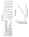
- simulation (1) will be described with reference to Figs. 3(a) and 3(b) .
- the shaft angle ⁇ , the grinding wheel helix angle of the axially opposite end portions, and the like are set accordingly.
- the amount of change in the grinding wheel helix angle can be found.
- This amount of change in the grinding wheel helix angle is the amount of change in the grinding wheel helix angle of the axially opposite end portions with respect to the grinding wheel helix angle of the axially intermediate portion, and is found as [(the grinding wheel helix angle of the axially intermediate portion) - (the grinding wheel helix angle of the axially opposite end portions)].
- the amount of change in the grinding wheel helix angle increases with increasing grinding wheel width.
- the grinding wheel helix angle gradually varies from the axially intermediate portion of the threaded grinding wheel 11 toward the axially opposite end portions thereof.
- the amount of change in the grinding wheel helix angle does not increase at a constant rate but the increment thereof gradually increases.
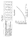
- simulation (2) will be described with reference to Figs. 4(a) and 4(b) .
- the amount of change in the grinding wheel helix angle increases with increasing grinding wheel width.
- the grinding wheel helix angle gradually varies from the axially intermediate portion of the threaded grinding wheel 11 toward the axially opposite end portions thereof.
- the amount of change in the grinding wheel helix angle does not increase at a constant rate but the increment thereof gradually increases.
- the amount of change in the grinding wheel helix angle increases with increasing grinding wheel width.
- the grinding wheel helix angle gradually varies from the axially intermediate portion of the threaded grinding wheel 11 toward the axially opposite end portions thereof.
- the amount of change in the grinding wheel helix angle does not increase at a constant rate but the increment thereof gradually increases.
- the amount of change in the grinding wheel helix angle increases with increasing grinding wheel width.
- the grinding wheel helix angle gradually varies from the axially intermediate portion of the threaded grinding wheel 11 toward the axially opposite end portions thereof.
- the amount of change in the grinding wheel helix angle does not increase at a constant rate but the increment thereof gradually increases.
- the amount of change, associated with a barrel shape, in the grinding wheel helix angle can be appropriately set by setting the grinding wheel helix angle in accordance with the axial length (position) from the axially intermediate portion of the threaded grinding wheel 11. Further, the grinding wheel helix angle of one of the axially opposite end portions of the threaded grinding wheel 11 is the angle obtained by adding the amount of change in the grinding wheel helix angle according to the length from the axially intermediate portion thereof to the one end portion, to the grinding wheel helix angle of the axially intermediate portion.
- the grinding wheel helix angle of the other of the axially opposite end portions of the threaded grinding wheel 11 is the angle obtained by subtracting the amount of change in the grinding wheel helix angle according to the length from the axially intermediate portion thereof to the other end portion, from the grinding wheel helix angle of the axially intermediate portion.
- the amount of change, associated with a barrel shape, in the grinding wheel helix angle can be appropriately set by setting the grinding wheel helix angle in accordance with the length from the axially intermediate portion of the threaded grinding wheel 11. Accordingly, machining can be performed with high accuracy.
- the barrel-shaped threaded tool for machining an internal gear according to the present invention has been applied to the threaded grinding wheel 11 for grinding a heat-treated workpiece W, but can also be applied to a shaving cutter for finishing an unheat-treated workpiece W.
- the present invention can be applied to a barrel-shaped threaded tool which can rapidly machine an internal gear.
Landscapes
- Engineering & Computer Science (AREA)
- Mechanical Engineering (AREA)
- Polishing Bodies And Polishing Tools (AREA)
- Finish Polishing, Edge Sharpening, And Grinding By Specific Grinding Devices (AREA)
Applications Claiming Priority (2)
| Application Number | Priority Date | Filing Date | Title |
|---|---|---|---|
| JP2008329566A JP5222125B2 (ja) | 2008-12-25 | 2008-12-25 | 内歯車加工用樽形ねじ状工具 |
| PCT/JP2009/069334 WO2010073848A1 (ja) | 2008-12-25 | 2009-11-13 | 内歯車加工用樽形ねじ状工具 |
Publications (2)
| Publication Number | Publication Date |
|---|---|
| EP2380689A1 true EP2380689A1 (de) | 2011-10-26 |
| EP2380689A4 EP2380689A4 (de) | 2016-12-21 |
Family
ID=42287469
Family Applications (1)
| Application Number | Title | Priority Date | Filing Date |
|---|---|---|---|
| EP09834652.1A Withdrawn EP2380689A4 (de) | 2008-12-25 | 2009-11-13 | Zylinderförmiges gewindewerkzeug zur maschinellen herstellung von zahnrädern mit innenverzahnung |
Country Status (6)
| Country | Link |
|---|---|
| US (1) | US8851962B2 (de) |
| EP (1) | EP2380689A4 (de) |
| JP (1) | JP5222125B2 (de) |
| CN (1) | CN102264498B (de) |
| TW (1) | TWI414377B (de) |
| WO (1) | WO2010073848A1 (de) |
Families Citing this family (10)
| Publication number | Priority date | Publication date | Assignee | Title |
|---|---|---|---|---|
| JP5854792B2 (ja) * | 2011-11-25 | 2016-02-09 | 三菱重工業株式会社 | 鼓形歯車状砥石のドレッシング方法及びディスク形ドレッサ |
| JP5829173B2 (ja) * | 2012-04-27 | 2015-12-09 | Ntn株式会社 | 車輪用軸受装置の製造方法 |
| EP3075481B1 (de) | 2014-05-30 | 2018-04-11 | Mitsubishi Heavy Industries Machine Tool Co., Ltd. | Schneidvorrichtung zum wälzschälen |
| JP2016107359A (ja) * | 2014-12-04 | 2016-06-20 | 三菱重工工作機械株式会社 | 歯車加工用砥石 |
| JP2017087389A (ja) * | 2015-11-16 | 2017-05-25 | いすゞ自動車株式会社 | ギアシェービング加工方法 |
| JP6367889B2 (ja) * | 2016-10-25 | 2018-08-01 | 三菱重工工作機械株式会社 | スカイビング加工用カッタ |
| CN108284278A (zh) * | 2018-02-01 | 2018-07-17 | 佛山科学技术学院 | 一种逐齿变螺旋角齿轮的激光切割成形加工装置 |
| DE102018112865B3 (de) * | 2018-05-29 | 2019-10-17 | Hartmetall-Werkzeugfabrik Paul Horn Gmbh | Wälzschälwerkzeug |
| JP7439403B2 (ja) * | 2019-07-12 | 2024-02-28 | 株式会社ジェイテクト | 砥石による研削加工方法 |
| GB2621058B (en) * | 2022-12-09 | 2024-10-09 | Univ Jiangsu | Method for designing cylindrical skiving tool without geometric relief angle |
Family Cites Families (16)
| Publication number | Priority date | Publication date | Assignee | Title |
|---|---|---|---|---|
| US2615359A (en) * | 1945-09-14 | 1952-10-28 | Parsons Marine Steam Turbine | Means for cutting projecting gear teeth |
| DE1124786B (de) * | 1958-12-16 | 1962-03-01 | Fritz Kleinstueck | Doppelkegeliger, schraubenfoermiger Abwaelzfraeser oder -schleifkoerper zur Herstellung von gerad- und schraegverzahnten, evolventenfoermigen Innenzahnkraenzen |
| FR2070927A5 (de) * | 1969-12-11 | 1971-09-17 | Arretche Jean Raymond | |
| JPS5138118B1 (de) * | 1970-03-30 | 1976-10-20 | ||
| JPS5138118A (de) | 1974-09-25 | 1976-03-30 | Ota Kinnosuke | |
| JPS582008B2 (ja) * | 1977-06-22 | 1983-01-13 | 相浦 正人 | 歯車創成用球形ホブ |
| CH650183A5 (de) * | 1981-01-27 | 1985-07-15 | Reishauer Ag | Verfahren zur bearbeitung eines zahnrades mittels eines rotierenden werkzeuges. |
| US4526053A (en) * | 1983-02-14 | 1985-07-02 | Millipore Corporation | Stabilized apparatus for converting rotational motion to linear motion |
| JPS6039022A (ja) * | 1983-08-12 | 1985-02-28 | Mitsubishi Heavy Ind Ltd | バレル型組立ホブ |
| JPS60194423U (ja) * | 1984-05-30 | 1985-12-25 | 三菱重工業株式会社 | 球形ウオ−ム砥石 |
| JP3002883B2 (ja) * | 1989-01-26 | 2000-01-24 | 株式会社神戸製鋼所 | 内歯車加工用ホブ |
| JP2683218B2 (ja) | 1994-05-10 | 1997-11-26 | ロングウェルジャパン株式会社 | クランク装置 |
| DE10222291A1 (de) * | 2002-05-18 | 2003-11-27 | Schlafhorst & Co W | Faserbandzuführeinrichtung |
| CN2757979Y (zh) * | 2004-12-31 | 2006-02-15 | 郑黄铮 | 多螺旋角度切削工具结构 |
| CN201086106Y (zh) | 2007-08-23 | 2008-07-16 | 施能嘉 | 成型内齿轮的组合式刀具 |
| JP4875601B2 (ja) | 2007-12-14 | 2012-02-15 | 三菱重工業株式会社 | 樽形ウォーム状工具 |
-
2008
- 2008-12-25 JP JP2008329566A patent/JP5222125B2/ja active Active
-
2009
- 2009-11-13 CN CN200980151859.XA patent/CN102264498B/zh active Active
- 2009-11-13 EP EP09834652.1A patent/EP2380689A4/de not_active Withdrawn
- 2009-11-13 WO PCT/JP2009/069334 patent/WO2010073848A1/ja not_active Ceased
- 2009-11-13 US US13/142,022 patent/US8851962B2/en active Active
- 2009-11-25 TW TW098140108A patent/TWI414377B/zh active
Non-Patent Citations (1)
| Title |
|---|
| See references of WO2010073848A1 * |
Also Published As
| Publication number | Publication date |
|---|---|
| TWI414377B (zh) | 2013-11-11 |
| JP5222125B2 (ja) | 2013-06-26 |
| US8851962B2 (en) | 2014-10-07 |
| US20110269383A1 (en) | 2011-11-03 |
| EP2380689A4 (de) | 2016-12-21 |
| CN102264498A (zh) | 2011-11-30 |
| CN102264498B (zh) | 2015-09-16 |
| TW201036738A (en) | 2010-10-16 |
| WO2010073848A1 (ja) | 2010-07-01 |
| JP2010149219A (ja) | 2010-07-08 |
Similar Documents
| Publication | Publication Date | Title |
|---|---|---|
| US8905819B2 (en) | Internal gear machining method | |
| US8851962B2 (en) | Barrel-shaped threaded tool for machining internal gear | |
| US9278398B2 (en) | Method for machining internally toothed gear and method for dressing tool used for same | |
| CN101808771B (zh) | 桶状蜗杆形刀具 | |
| CN102574271B (zh) | 桶形螺纹状工具的制造方法 | |
| CN101778698A (zh) | 用于圆筒蜗杆状刀具的打磨方法和打磨设备及内齿轮磨床 | |
| CN100525975C (zh) | 磨削旋转齿轮剃齿刀的齿侧面用的方法和机器 | |
| US8979610B2 (en) | Method for dressing threaded grinding stone for internal gear grinding | |
| US9120167B2 (en) | Method for manufacturing screw-shaped tool | |
| JP5524397B2 (ja) | 樽形ねじ状工具の製作方法 | |
| JP2001252823A (ja) | 鼓形ウオームの歯切り方法 | |
| JPH1086017A (ja) | 歯車の加工方法および歯車加工用バリ取り装置 | |
| JPS5943254B2 (ja) | 平歯車を製作又は加工する装置 | |
| JP7793178B2 (ja) | 歯車仕上げ用砥石及びその製造方法 |
Legal Events
| Date | Code | Title | Description |
|---|---|---|---|
| PUAI | Public reference made under article 153(3) epc to a published international application that has entered the european phase |
Free format text: ORIGINAL CODE: 0009012 |
|
| 17P | Request for examination filed |
Effective date: 20110617 |
|
| AK | Designated contracting states |
Kind code of ref document: A1 Designated state(s): AT BE BG CH CY CZ DE DK EE ES FI FR GB GR HR HU IE IS IT LI LT LU LV MC MK MT NL NO PL PT RO SE SI SK SM TR |
|
| DAX | Request for extension of the european patent (deleted) | ||
| RAP1 | Party data changed (applicant data changed or rights of an application transferred) |
Owner name: MITSUBISHI HEAVY INDUSTRIES MACHINE TOOL CO., LTD. |
|
| RA4 | Supplementary search report drawn up and despatched (corrected) |
Effective date: 20161123 |
|
| RIC1 | Information provided on ipc code assigned before grant |
Ipc: B23F 21/02 20060101AFI20161117BHEP Ipc: B23F 21/16 20060101ALI20161117BHEP |
|
| STAA | Information on the status of an ep patent application or granted ep patent |
Free format text: STATUS: THE APPLICATION IS DEEMED TO BE WITHDRAWN |
|
| 18D | Application deemed to be withdrawn |
Effective date: 20170620 |