EP2380701B1 - Method for trimming an ophthalmic spectacle lens - Google Patents
Method for trimming an ophthalmic spectacle lens Download PDFInfo
- Publication number
- EP2380701B1 EP2380701B1 EP11290178A EP11290178A EP2380701B1 EP 2380701 B1 EP2380701 B1 EP 2380701B1 EP 11290178 A EP11290178 A EP 11290178A EP 11290178 A EP11290178 A EP 11290178A EP 2380701 B1 EP2380701 B1 EP 2380701B1
- Authority
- EP
- European Patent Office
- Prior art keywords
- blocking position
- tool
- machining
- blocking
- intersection
- Prior art date
- Legal status (The legal status is an assumption and is not a legal conclusion. Google has not performed a legal analysis and makes no representation as to the accuracy of the status listed.)
- Active
Links
Images


Classifications
-
- B—PERFORMING OPERATIONS; TRANSPORTING
- B24—GRINDING; POLISHING
- B24B—MACHINES, DEVICES, OR PROCESSES FOR GRINDING OR POLISHING; DRESSING OR CONDITIONING OF ABRADING SURFACES; FEEDING OF GRINDING, POLISHING, OR LAPPING AGENTS
- B24B9/00—Machines or devices designed for grinding edges or bevels on work or for removing burrs; Accessories therefor
- B24B9/02—Machines or devices designed for grinding edges or bevels on work or for removing burrs; Accessories therefor characterised by a special design with respect to properties of materials specific to articles to be ground
- B24B9/06—Machines or devices designed for grinding edges or bevels on work or for removing burrs; Accessories therefor characterised by a special design with respect to properties of materials specific to articles to be ground of non-metallic inorganic material, e.g. stone, ceramics, porcelain
- B24B9/08—Machines or devices designed for grinding edges or bevels on work or for removing burrs; Accessories therefor characterised by a special design with respect to properties of materials specific to articles to be ground of non-metallic inorganic material, e.g. stone, ceramics, porcelain of glass
- B24B9/14—Machines or devices designed for grinding edges or bevels on work or for removing burrs; Accessories therefor characterised by a special design with respect to properties of materials specific to articles to be ground of non-metallic inorganic material, e.g. stone, ceramics, porcelain of glass of optical work, e.g. lenses, prisms
-
- B—PERFORMING OPERATIONS; TRANSPORTING
- B24—GRINDING; POLISHING
- B24B—MACHINES, DEVICES, OR PROCESSES FOR GRINDING OR POLISHING; DRESSING OR CONDITIONING OF ABRADING SURFACES; FEEDING OF GRINDING, POLISHING, OR LAPPING AGENTS
- B24B13/00—Machines or devices designed for grinding or polishing optical surfaces on lenses or surfaces of similar shape on other work; Accessories therefor
- B24B13/005—Blocking means, chucks or the like; Alignment devices
- B24B13/0055—Positioning of lenses; Marking of lenses
-
- B—PERFORMING OPERATIONS; TRANSPORTING
- B24—GRINDING; POLISHING
- B24B—MACHINES, DEVICES, OR PROCESSES FOR GRINDING OR POLISHING; DRESSING OR CONDITIONING OF ABRADING SURFACES; FEEDING OF GRINDING, POLISHING, OR LAPPING AGENTS
- B24B41/00—Component parts such as frames, beds, carriages, headstocks
- B24B41/06—Work supports, e.g. adjustable steadies
- B24B41/061—Work supports, e.g. adjustable steadies axially supporting turning workpieces, e.g. magnetically, pneumatically
- B24B41/062—Work supports, e.g. adjustable steadies axially supporting turning workpieces, e.g. magnetically, pneumatically between centres; Dogs
Definitions
- the present invention relates to a method of trimming an ophthalmic lens to a desired contour, for mounting in a spectacle frame.
- It relates more specifically to the determination of a locking position of the lens on a locking medium on which the lens is maintained during its trimming.
- This method is particularly suitable for trimming ophthalmic lenses whose contour has a complex shape, including negative curvature zones.
- an ophthalmic lens for mounting on a circled, semi-rimless or no-circle (or "pierced") spectacle frame is achieved by acquiring the desired contour according to which the ophthalmic lens is to be cut off to fit to the shape of this eyeglass frame.
- This contour is positioned on the lens according to the optical reference of the lens so that the latter is, when worn, properly positioned in front of the eyes of the wearer. The lens is then cut off following this desired contour.
- ophthalmic lenses intended to be cut off according to contours of complex shapes including, for example, curved zones towards the center of the lens, called zones of negative curvature.
- These negative curvature zones generally correspond to decorative details of the contour of the lens and need to be machined by a tool of diameter less than the diameter of the grinding wheel commonly used to cut the lens. We for example, uses a milling tool of a few millimeters in diameter.
- the internal cutting limit is defined around the blocking support and corresponds to the zone around this support in which the machining tool in question can not access, because of the risk of interference between the tool (or the door tool) and the locking bracket.
- the invention it is possible to detect, even before the setting of the blocking support on the lens (generally at the optical center or at the boxing center of the lens), the risks of interference between the tool of machining and blocking bracket.
- envelope will be used to designate the surface that delimits a volume considered.
- the envelope of an object in motion will in particular designate the surface in which is circumscribed all the positions of the object when it moves according to the movement considered.
- the technical part of the optician's profession is to mount a pair of ophthalmic lenses on a frame selected by the future wearer of the pair of glasses.
- This clipping operation is generally performed in three successive stages of roughing, finishing and finishing.
- the roughing step consists of bringing the initial contour of the lens back to a near or identical contour of the desired contour.
- the finishing operation consists of beveling the edge of the lens if it is intended to be mounted on a circled spectacle frame, or to groove the edge of the lens if it is intended to be mounted on a frame of semi-rimmed glasses.
- the finishing step consists of polishing and chamfering as necessary the sharp edges of the edge of the lens.
- the clipping method according to the invention applies here to all of these steps.
- an ophthalmic lens 10 has two front 14 and rear 15 optical faces, and an initially circular wafer 16 which should be returned to the shape of the desired contour, so that the ophthalmic lens can then be attached to the selected eyeglass frame.
- the method according to the present invention applies to any type of contour, regular or not. However, it applies particularly advantageously to ophthalmic lenses to be cut on desired contours of irregular shapes, and to assemble with frames of pierced type spectacles (In which the branches and the bridge of the frame have means for fixing to drilling holes made in the lenses).
- the desired contour 11 considered in projection in a general mean plane of the ophthalmic lens not yet cut-off, comprises a regular lower sector and an irregular upper sector AD.
- This upper sector is formed of several complex regions delimited respectively by the points A, B, C and D.
- Each complex region A-B, B-C, C-D has one or more zones of negative curvature. These areas of negative curvature are areas in which the desired contour 11 is concave.
- boxing center forms the origin of the benchmark of the reference of the ophthalmic lens.
- the average plane of the ophthalmic lens is defined as the plane which contains the circular rear edge of the lens which has not yet been cut off.
- the desired contour 11 then corresponds to the projection in this mean plane of the three-dimensional contour along which the lens must be cut off.
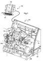
- this ophthalmic lens 10 To cut off this ophthalmic lens 10, it is placed in a machining device 200 known in itself, such as that described in the document W02008 / 043910 .
- this computing and control device 100 is integrated in the electronic and / or computer system of the grinder 200.
- the support means 210 of the ophthalmic lens 10 here more specifically comprise two shafts and rotation drive 211 of the ophthalmic lens 10 to be cut. These two shafts 211 are aligned with each other along the blocking axis A2.
- Each of these shafts 211 has a free end which faces the other, one of which is equipped with a locking nose 214 of the ophthalmic lens 10 and the other of which is equipped with a receiving means 213. a locking accessory 215 of the lens (prepositioned on the lens at the time of its blocking).
- This locking accessory is conventionally positioned on the ophthalmic lens at a given point and with a given orientation, which makes it possible to locate the position of the reference frame of the ophthalmic lens relative to the reference frame of the frame 203 of the machining device 200.
- this blocking accessory 215 comprises a body arranged to cooperate with the corresponding shaft 211 of the grinder 200, and an adhesive patch arranged to stick to the front optical face 14 of the ophthalmic lens.
- the nose and the locking accessory 214, 215. It is then possible to define around the axis of blocking A2 a surface, called inaccessibility envelope B1, in which it is not possible to machine the ophthalmic lens 10. Since the nose and locking accessory 214, 215 here have the same contour of known transverse dimension (typically, a circular contour of known or rectangular diameter of known sides), the inaccessibility envelope B1 is defined as the cylinder of revolution about the locking pin A2, which has a diameter equal to that of the nose and locking accessory 214 215 (or slightly greater than this diameter, given the possible deformations of these nose and locking accessory).
- a first of the two shafts 211 is fixed in translation along the blocking axis A2.
- the second of the two shafts 211 is conversely mobile in translation along the blocking axis A2 to achieve the compression in axial compression of the ophthalmic lens 10 between the two shafts.
- the large grinding wheel 220 is a conventional grinding wheel, which comprises a cutting surface defining, in its rotation about the axis A3, a cutting envelope of revolution about this axis A3, having a diameter greater than or equal to 80 millimeters, for example equal to 155 millimeters.
- the grinder 231 is a wheel of smaller diameter than the grinding wheel 220, which comprises a cutting surface defining, in its rotation about the axis A5, a revolution cutting envelope about this axis A5, preferably having a smaller diameter. at 80 millimeters, for example equal to 11 millimeters.
- the cutter 230 comprises a cutting edge defining, in its rotation about the axis A6, a cutting envelope of revolution about this axis A6, which has a diameter less than 10 millimeters and preferably less than 5 millimeters, for example equal at 1.4 millimeters.
- the large grinding wheel 220 and the grinder 231 are respectively carried by an axis and a mandrel. They have diameters much greater than those of this axis and this mandrel. During machining of the lens, these tool holders are therefore not likely to interfere with the 211 locking shafts of the ophthalmic lens.
- the cutter 230 is however supported by a mandrel 240, itself supported by the finisher 235, whose dimensions (transverse to the axis A6) are greater than those of the cutter. More specifically here, the cutter 230 is positioned in such a way on the finishing module 235 that the latter may interfere with the locking shafts 211 of the ophthalmic lens.
- finishing module 235 a surface, called the security envelope B2, in which are included the mandrel 240 and the finisher 235.
- the safety shells of the large grinding wheel 220 and the grinder 231 are formed by their cutting shells since their tool holders are not likely to interfere with the shafts 211 for blocking the ophthalmic lens.
- the security envelope B2 must never intersect the envelope of inaccessibility B1 in order to avoid, on the one hand, any risk of machining of the nose and locking accessory 214, 215, and, on the other hand, any risk of interference between the tool in question (or the door tool) and the locking shafts 211 of the ophthalmic lens.
- this internal cutting limit 12, 13 corresponds to the envelope in which the cutting surface moves. of the tool considered during its movement around the locking shafts 211 of the lens in a permitted functional displacement range.
- each tool is associated with an inner cutting limit 12, 13 which is specific to it.
- the internal cutting limits 12 associated with the grinding wheel 220 and the grinding wheel 231 are combined. They have cylindrical shapes of revolution around the blocking axis A2, of diameter equal to that of the inaccessibility envelope B1.
- the internal cutting limit 13 associated with the cutter 230 also has a cylindrical shape of revolution about the blocking axis A2, but it has a diameter greater than that of the inaccessibility envelope B1.
- each inner cutting limit will then not only associated with a tool, but also to a type of locking accessory.
- the desired contour 11 of the ophthalmic lens 10 to be cut out comprising, as shown in FIG. figure 3 , AB complex regions, BC, CD, the clipping of the lens can be achieved using the only grinding wheel 220. It is indeed in the case where the diameter of the grinding wheel 220 is too large to respect the geometry of the desired contour 11 in its negative curvature areas having a too pronounced concavity.
- the trimming could then be performed using the single mill 231.
- the use of a small diameter tool is more expensive than that of a large diameter tool.
- Several tools will therefore be used here for machining the ophthalmic lens 10 according to the desired contour 11.
- the calculation and control device 100 determines which regions of the desired contour 11 of the ophthalmic lens 20 will be machined by which tool 220, 230, 231, depending on the geometrical characteristics of the lens. this desired contour 11 and as a function of the diameters of the cutting envelopes of the tools 220, 230, 231.
- the computing and control device 100 begins by acquiring, in one way or another, the desired contour 11.
- This desired contour 11 can for example be obtained by simply searching, in a register of a database, a record which is associated with the reference of the selected eyeglass frame and which stores the desired contour.
- a regularly updated database register is however necessary.
- this desired contour 11 can be obtained by capturing a digital snapshot of the presentation eyeglass frame that the optician has at its disposal, and by processing this snapshot to determine the two-dimensional coordinates of a set of points characterizing the shape. slices of the lenses of this presentation frame.
- the desired contour 11 can also be obtained by palpating the edge of the lenses of this presentation frame with a conventional reader, such as that described in the patent.
- the calculation and control device 100 will thus have acquired the two-dimensional coordinates of a plurality of points characterizing the geometry of the desired contour 11.
- the calculation and control device 100 then executes a desired contour analysis algorithm 11 in order to determine a first region of the desired contour 11 comprising the points of this contour for which the use of the grinding wheel 220 is possible to cut the ophthalmic lens without damaging the shape of the desired contour.
- the algorithm calculates for this purpose the position of the cutting envelope 30 of the grinding wheel 220 when it is tangent to the contour at this point. This position corresponds to the position of the grinding wheel 220 when it is in position to machine the lens 10 according to the desired contour 11 at this point.
- the algorithm searches for the points of the desired contour 11 that are inside this first cutting envelope, that is to say located on the side of the arc corresponding to the wheel 220, if exists. These points correspond to the additional points trimmed by the grinding wheel 220 when it is machining the lens 10 at the considered point of the desired contour 11.
- the algorithm can thus determine the complex sectors of the contour in which the use of the grinding wheel 220 is not necessary. possible. In the case of the desired contour 11 shown on the figure 3 this sector corresponds to the upper sector of the desired contour 11, between the points A and D.
- the algorithm then checks whether the whole of this upper sector can be machined using the grinder 231.
- the algorithm proceeds in the same manner as with the grinding wheel 220, this time considering only the points of the upper sector of the desired contour 11.
- the algorithm can thus determine the complex regions of the desired contour 11 in which the use of the grinder 231 is not possible. In the case of the desired contour 11 shown on the figure 3 these complex regions are between the points A and B on the one hand, and C and D on the other hand.
- the algorithm finally verifies whether these two complex regions AB and CD can be machined using the mill 230. If this is not the case, it displays an error message on the screen 102, meaning that optician that the trimming of the ophthalmic lens is not possible.
- the algorithm for carrying out this method of searching for a final blocking position P F is decomposed into successive steps illustrated on FIG. figure 4 .
- the computing and control device 100 resets a counter.
- the value N stored in this counter is then equal to 1.
- the computing and control device 100 looks in the database register to which it has access, on the one hand, the internal cutting limit 12 associated with the grinding wheel 220 and on the other hand. grinder 231, and, on the other hand, the internal cutting limit 13 associated with the cutter 230.
- the calculation and control device 100 acquires the two-dimensional coordinates of the points characterizing the desired contour 11, then calculates the position of the boxing center P 1 .
- the calculation and control device 100 determines whether at least a portion of the desired contour 11 intended to be machined using the grinding wheel 220 or the grinder 231 has a non-zero intersection with the inner cutting limit 12 and if at least a portion of the desired contour 11 intended to be machined using the cutter 230 has a non-zero intersection with the inner cutting limit 13.
- the calculation and control device 100 superimposes for this purpose the internal cutting limits 12, 13 and the desired contour 11, so that the centers of the circles representative of these inner cutting limits 12, 13 are merged with the boxing center. P 1 . It simulates the blocking of the ophthalmic lens 10 at its boxing center P 1 .
- the first equation will correspond to that of the desired contour 11.
- the second equation corresponds to the equation of the circle representative of the inner cutting limit 12, while in the second system it corresponds to the equation of the circle representative of the inner cutting limit 13.
- part Q 11 - Q 12 of the complex portion AB intended to be cut by the cutter 230 is situated inside the internal cutting limit 13. It can also be seen that part Q 21 - Q 22 of the complex portion BC intended to be cut by the grinder 231 is located within the inner limit of section 12. It is therefore understood that by placing the locking accessory 215 on the ophthalmic lens 10 in such a way that it is centered on the boxing center P 1 , it will appear during the machining of the lens a problem of interference between the shafts 211 of locking the lens and the tools or tool holders of the grinder 200.
- the calculation and control device 100 therefore suspends the blocking of the ophthalmic lens 10 to find a new blocking position P N modified with respect to the boxing center P 1 , in the hope that in this position, the desired contour 11 does not present more intersection with inner cutting boundaries 12, 13.
- the computing and control device 100 calculates an offset vector V1 which will make it possible to shift the blocking point in a position likely to solve the aforementioned interference problems.
- the calculation and control device 100 locates, for each intersection zone Q 11 - Q 12 , Q 21 - Q 22 , the segment of radius S 1, S 2 of the circle representative of the inner cutting limit 12, 13 associated with this intersection zone, which is located between the desired contour 11 and this circle, and which has the greatest length.
- the calculation and control device 100 then proceeds to shift the position of the blocking point from the boxing center P 1 to the new blocking point P N , according to this offset vector V1.
- the offset vector can be calculated differently. It may for example be provided that it has a length identical to that of the vector V1, but that it is oriented otherwise. Its orientation can for example be determined by calculating the direction of the average normal to the desired contour at the intersection areas Q 11 - Q 12 , Q 21 - Q 22 , that is to say the direction of the combination of two normal vectors, on average, to the two intersection zones.
- the calculation and control device 100 increments the value N stored in the counter by one unit, and then verifies that the new value N is less than a predetermined threshold N 0 .
- the calculation and control device 100 again implements the steps E4 to E8 mentioned above, to determine whether the contouring of the ophthalmic lens according to the desired contour 11, as positioned in its new locking position P N , and with the tools 220, 230, 231 provided, is possible.
- the calculation and control device 100 displays on the screen 102 an error message indicating to the optician that the trimming of the ophthalmic lens to using the grinder 200 is not possible. It also displays an image of the desired contour 11 with, in red, the part (s) of this contour which is likely to pose problems of interference. In this case, the optician can possibly intervene by modifying on the screen the displayed shape of the desired contour in order to enlarge it at the level of the red zone. Thus, the computing and control device 100 can again try to find a final locking point P F which is suitable.
- the optician proceeds to block the ophthalmic lens 10 at the level of this final blocking position P F.
- the position of the desired contour 11 in the reference frame of the ophthalmic lens 10 being determined, the locking accessory 215 is bonded to the front optical face 14 of the ophthalmic lens 10 at the final locking point P F identified by ratio to desired contour 11.
- the ophthalmic lens 10 equipped with its locking accessory 215 is then locked between the two shafts 211 of the grinder 200 to be cut along the desired contour 11.
- the ophthalmic lens 10 cut away according to the desired contour 11 is therefore able to be attached to the selected spectacle frame if it is of the rimmed or semi-rimmed type.
- the spectacle frame is of the type without a circle, it is necessary to make drilling holes or notches in the lens so that the bridge and the corresponding branch of the spectacle frame can be hooked to it.
- the drilling holes are generally made in the lens in full material, by a drill bit provided on the grinder 200, along a determined axis.
- the position of this axis is marked with respect to the desired contour 11 and its orientation relative to the lens is chosen so that it is orthogonal to the front face of the lens at the piercing point.
- Notches form nicks in the edge of the lens Ophthalmic 10. As a result, they can be made both by the milling cutter 230 and by the drill bit. They could even be made directly during the trimming of the lens, which however is not the subject of this presentation. On the contrary, here, these notches and drilling holes will be made after trimming the ophthalmic lens, even though the lens is still locked between the shafts 211 of the grinder 200.
- the new final locking position P F ' will be chosen so as to avoid any interference between the tool holder and the shafts 211 as well during the trimming as during the drilling or the notching of the ophthalmic lens.
- step i) the positions of the edges of the notches or the drilling holes are acquired in projection in the middle plane of the ophthalmic lens (shown in FIG. figure 3 ). It will be noted here that in this projection, the edges of the front and rear mouths of each piercing hole will generally be slightly offset, since the drilling axis is generally not parallel to the axis of the projection used. The edge considered will then preferentially correspond to the overall contour which envelops the projections of the front and rear mouths of the piercing hole in the middle plane of the ophthalmic lens.
- Steps ii) and iii) will be implemented following a method identical to that described supra, of shifting the final locking point P F to find a new final locking point P F 'which satisfies the conditions required.
- the ophthalmic lens is subjected to other machining operations by the grinder 200.
- it may be provided an engraving operation of areas of interest specific to the lens, such as the periphery of its front face, by means of the free end of the cutter 230 or a diamond tip provided for this purpose.
- the method for determining the final locking position P F is not iterative, but instead consists in considering a plurality of alternative locking positions, for example in the number of one hundred, then in determining for each of these alternative blocking positions whether the areas of the desired contour 11 to be cut with the aid of the grinding wheel 220 or the grinder 231 intersect the inside cutting limit 12 and whether the areas AB and CD of the desired contour 11 to detour using the cutter 230 intersects the inner cutting limit 13.
- the calculation and control device displays an error message on the screen.
- this locking position is selected as being the final locking position at which the locking accessory will be fixed on the lens.
- the blocking position selected as the final blocking position is the one which, among these alternative blocking positions, is the closest to the boxing center.
- the selected blocking point could be the one closest to the center of gravity (or "barycenter") of the desired contour 11 (or, alternatively, the center of the circular initial contour of the ophthalmic lens).
- the internal cutting limits are acquired not in the form of three-dimensional surface envelopes, but on the contrary in the form of two-dimensional linear envelopes, for example in the form of simple circles such as those represented on the figure 3 .
- the calculation unit will then transmit to the grinder 200 the final locking position P F , so that the grinder 200 takes into account the information that the ophthalmic lens 10 is blocked not at the boxing center P 1 , but at another point distinct from this boxing center.
- provision may be made for the ophthalmic lens to be cut off using a machining tool having a given axis of rotation and a variable diameter along this axis of rotation.
- provision may be made to use a cutter having a first end portion held by the tool holder, a substantially cylindrical central portion intended to cut the ophthalmic lens, and a second free end portion, of greater diameter than that of the central portion, designed to chamfer the ophthalmic lens.
- the free end portion of the cutter may then interfere with the locking shafts 211 during operations of trimming the lens by the central portion of the cutter.
- the two parts of the cutter then behave in the manner of two separate tools that would be attached to one another. We can then define for this single strawberry two internal cutting limits, each associated with the two parts of this strawberry.
- the initial blocking point of the ophthalmic lens is not the boxing center of the desired contour, but rather the optical center of the ophthalmic lens or its center of gravity.
Landscapes
- Engineering & Computer Science (AREA)
- Mechanical Engineering (AREA)
- Chemical & Material Sciences (AREA)
- Ceramic Engineering (AREA)
- Inorganic Chemistry (AREA)
- Grinding And Polishing Of Tertiary Curved Surfaces And Surfaces With Complex Shapes (AREA)
- Eyeglasses (AREA)
Claims (14)
- Zuschneideverfahren für ein Brillenglas (10) gemäß einer gewünschten Kontur (11) mittels einer Bearbeitungsvorrichtung (200), die eine Einklemmhalterung (210) für das Brillenglas (10) und mindestens ein erstes Bearbeitungswerkzeug (220) umfasst, das sich um eine erste mobile Achse (A3) in Bezug zur Einklemmhalterung dreht, wobei das Verfahren folgende Schritte umfasst:- a) Erzielen einer internen Schnittgrenze (12) für das erste Bearbeitungswerkzeug (220), die in einem Referenzsystem der Bearbeitungsvorrichtung (200) definiert ist,- b) Definieren einer ursprünglichen Einklemmposition (P1) des Brillenglases (10) und seiner gewünschten Kontur (11) auf der Einklemmhalterung (210) in dem Referenzsystem der Bearbeitungsvorrichtung (200),- c) Berechnen, ob mindestens ein Teil der gewünschten Kontur (11), so wie sie in der ursprünglichen Einklemmposition (P1) positioniert ist, eine Schnittstelle ungleich null (Q21 - Q22) mit der internen Schnittgrenze (12) aufweist,- d) Definieren als endgültige Einklemmposition (PF) entweder die ursprüngliche Einklemmposition (P1), die unverändert ist, wenn die im Schritt c) berechnete Schnittstelle null ist, oder im entgegengesetzten Fall, eine in Bezug zur ursprünglichen Einklemmposition (P1) veränderte Einklemmposition, damit die gewünschte Kontur (11), so wie sie in der veränderten Einklemmposition neu positioniert wurde, mit der dem ersten Werkzeug zugeordneten internen Schnittgrenze (12) keine Schnittstelle aufweist,- e) Blockieren des Brillenglases (10) in der Einklemmhalterung (210) in der endgültigen Einklemmposition (PF),- f) Zuschneiden des Brillenglases (10) entsprechend der gewünschten Kontur (11) mit mindestens dem ersten Bearbeitungswerkzeug (220).
- Verfahren nach Anspruch 1, bei dem,- man, während die Bearbeitungsvorrichtung (200) eine Vielzahl von Bearbeitungswerkzeugen (220, 230, 231) umfasst, mindestens zwei verschiedene Bearbeitungswerkzeuge (220, 230) auswählt, darunter das erste Werkzeug (220) und mindestens ein anderes um eine in Bezug zur Einklemmhalterung (210) bewegliche Achse (A6) drehbares Werkzeug (230), wobei jedes Werkzeug (220, 230) dazu bestimmt ist, einen ihm zugeordneten Teil der gewünschten Kontur (11) zu bearbeiten,- man im Schritt a) für jedes Bearbeitungswerkzeug (220, 230) eine in einem Referenzsystem der Bearbeitungsvorrichtung (200) definierte interne Schnittgrenze (12, 13) erzielt, wobei sich die interne Schnittgrenze (12) des ersten Werkzeugs (220) von der internen Schnittgrenze (13) des anderen Werkzeugs unterscheidet,- man im Schritt c) für jedes Bearbeitungswerkzeug (220, 230) berechnet, ob der ihm zugeordnete Teil der gewünschten Kontur (11), so wie in der ursprünglichen Einklemmposition (P1) positioniert, eine Schnittstelle (Q11 - Q12' Q21Q22) ungleich null mit der dem jeweiligen Bearbeitungswerkzeug (220, 230) zugeordneten internen Schnittgrenze (12, 13) aufweist,- man im Schritt d) als endgültige Einklemmposition (PF) entweder die ursprüngliche Einklemmposition (P1) definiert, die unverändert ist, wenn die in Schritt c) berechneten Schnittstellen null sind, oder im entgegengesetzten Fall, eine in Bezug zur ursprünglichen Einklemmposition (P1) veränderte Einklemmposition, damit die gewünschte Kontur (11), so wie in der veränderten Einklemmposition repositioniert, keine Schnittstelle mit den internen Schnittgrenzen (12, 13) aufweist, die jeweils den verschiedenen Bearbeitungswerkzeugen (220, 230) zugeordnet sind,- man im Schritt f) das Brillenglas gemäß der gewünschten Kontur (11) mit den verschiedenen Bearbeitungswerkzeugen (220, 230) zuschneidet, wobei ein erster Teil der gewünschten Kontur (11) mit dem ersten Bearbeitungswerkzeug (220) zugeschnitten wird, und der andere Teil der gewünschten Kontur (11) mit dem anderen Bearbeitungswerkzeug (230) zugeschnitten wird.
- Verfahren nach einem der Ansprüche 1 und 2, bei dem der Schritt d), wenn die im Schritt c) berechnete Schnittstelle (Q11 - Q12, Q21 - Q22) ungleich null ist, folgende Unterschritte umfasst:- d1) eine alternative Einklemmposition (PN) ermitteln, die sich von der ursprünglichen Einklemmposition (P1) unterscheidet,- d2) für jedes Bearbeitungswerkzeug (220, 230) und für diese alternative Einklemmposition (PN) berechnen, ob mindestens ein Teil der gewünschten Kontur (11), so wie in dieser alternativen Einklemmposition (PN) neu positioniert, eine Schnittstelle (Q'11 - Q'12) ungleich null mit der dem jeweiligen Bearbeitungswerkzeug (220, 230) zugeordneten internen Schnittgrenze (12, 13) aufweist,- d3) die Schritte d1) und d2) wiederholen, solange der Schritt d2) ein Schnittstellenergebnis (Q'11 - Q'12) ungleich null ergibt.
- Verfahren nach einem der Ansprüche 1 und 2, bei dem der Schritt d), wenn die in Schritt c) berechnete Schnittstelle (Q11 - Q12, Q21 - Q22) ungleich null ist, folgende Unterschritte umfasst:- d'1) eine Vielzahl von alternativen Einklemmpositionen ermitteln, die sich von der ursprünglichen Einklemmposition (P1) unterscheiden,- d'2) für jedes Werkzeug und für jede der alternativen Einklemmpositionen berechnen, ob mindestens ein Teil der gewünschten Kontur, so wie in der jeweiligen alternativen Einklemmposition positioniert, eine Schnittstelle ungleich null mit der dem jeweiligen Werkzeug zugeordneten internen Schnittgrenze aufweist,- d'3) unter diesen alternativen Einklemmpositionen die veränderte Einklemmposition auswählen.
- Verfahren nach Anspruch 4, bei dem im Schritt d) die veränderte Einklemmposition als die Einklemmposition des Brillenglases in der Einklemmhalterung definiert wird, die unter den alternativen Einklemmpositionen der ursprünglichen Einklemmposition am nächsten liegt.
- Verfahren nach Anspruch 4, bei dem im Schritt d) die veränderte Einklemmposition als die Einklemmposition des Brillenglases in der Einklemmhalterung definiert wird, die unter den alternativen Einklemmpositionen der dem Schwerpunkt der gewünschten Kontur (11) am nächsten gelegene Position ist.
- Verfahren nach einem der vorausgehenden Ansprüche, bei dem man im Schritt c) den Radiusabschnitt (S1, S2) um die ursprüngliche Einklemmposition (P1) berechnet, der sich innerhalb des Schnittpunktes (Q11-Q12, Q21-Q22) befindet und die größte Länge aufweist und bei dem im Schritt d) die veränderte Einklemmposition (PN) aus mindestens einer Translation der ursprünglichen Einklemmposition (P1) entlang der Richtung des Radiusabschnittes (S1, S2) hervorgeht.
- Verfahren nach Anspruch 7, bei dem diese Translation über eine Distanz ausgeführt wird, die der Länge des Radiusabschnittes entspricht.
- Verfahren nach einem der Ansprüche 7 und 8, bei dem man im Schritt c), während mindestens zwei Schnittstellen (Q11-Q12, Q21-Q22) ungleich null zwischen der gewünschten Kontur (11) und jeder internen Schnittgrenze (12, 13) resultieren, für jeden Schnittpunkt (Q11-Q12. Q21-Q22) den Radiusabschnitt (S1, S2) um die ursprüngliche Einklemmposition (P1) berechnet, der sich innerhalb der relevanten Schnittstelle (Q11-Q12' Q21-Q22) befindet und die größte Länge aufweist und bei dem im Schritt d) die veränderte Einklemmposition (PN) aus mindestens einer Kombinierung von Translationen der ursprünglichen Einklemmposition (P1) entlang der Richtungen der Radiusabschnitte (S1, S2), die jeweils den mindestens zwei Schnittstellen (Q11-Q12, Q21-Q22) zugeordnet sind, hervorgeht.
- Verfahren nach einem der vorausgehenden Ansprüche, das für ein Brillenglas angewendet wird, das mittels einem zweiten Bearbeitungswerkzeug gebohrt oder mit einem Wellenschliff versehen werden soll, um in eine rahmenlose Brillenfassung montiert zu werden und welches umfasst:- einen Schritt zum Erzielen einer internen Schnittgrenze des zweiten Bearbeitungswerkzeugs, die im Referenzsystem der Bearbeitungsvorrichtung definiert ist,- einen Schritt zum Erfassen der Randpositionen der Zacken oder Bohrlöcher in einem der gewünschten Kontur zugeordneten Referenzsystem,- zwischen den Schritten d) und e) einen Berechnungsschritt, um zu ermitteln, ob die Ränder der Zacken oder Bohrlöcher mit der internen Schnittgrenze, die diesem zweiten Werkzeug zugeordnet ist, eine Schnittstelle ungleich null aufweist, wenn die gewünschte Kontur wieder in der endgültigen Einklemmposition positioniert ist, und- einen Schritt zum Ermitteln einer neuen endgültigen Einklemmposition, wenn eine Schnittstelle erkannt worden ist, die sich von der besagten endgültigen Einklemmposition unterscheidet und derart ist, dass zum einen die gewünschte, neu in die neue endgültige Einklemmposition positionierte Kontur, keine Schnittstelle mit der dem zweiten Werkzeug zugeordneten internen Schnittgrenze aufweist, und derart, dass zum anderen die Ränder der Zacken oder Bohrlöcher keine Schnittstelle mit dieser internen Schnittgrenze aufweisen.
- Verfahren nach einem der vorausgehenden Ansprüche, bei dem die interne Schnittgrenze (12, 13) jedes Bearbeitungswerkzeugs (220, 230) von der Geometrie des Bearbeitungswerkzeugs (220, 230) und/oder eines Werkzeugträgers (240), der dieses Bearbeitungswerkzeug (220, 230) hält, abhängt, sowie von der Geometrie der Einklemmhalterung (210) des Brillenglases (10) abhängt.
- Verfahren nach einem der vorausgehenden Ansprüche, bei dem die interne Schnittgrenze (12, 13) jedes Bearbeitungswerkzeugs (220, 230) vom Winkel abhängt, den die Drehachse (A6) des relevanten Werkzeugs mit einer Einklemmachse (A2) bildet, um die sich das Brillenglas (10) in Bezug zu den Bearbeitungswerkzeugen (220, 230) während seines Zuschneidens im Schritt f) dreht.
- Verfahren nach einem der vorausgehenden Ansprüche, bei dem die interne Schnittgrenze (12, 13) jedes Bearbeitungswerkzeuges (220, 230) anhand eines Verzeichnisses erhalten wird, dessen jeweiliges Abspeichern ein Kennzeichen eines Bearbeitungswerkzeuges (220, 230) und eine diesem Bearbeitungswerkzeug (220, 230) zugeordnete interne Schnittgrenze (12, 13) enthält.
- Verfahren nach einem der vorausgehenden Ansprüche, bei dem die Schritte a) bis d) durch eine Berechnungsvorrichtung ausgeführt werden, die sich von der Bearbeitungsvorrichtung (200) unterscheidet, und die zwischen den Schritten d) und f) einen Übertragungsschritt der endgültigen Einklemmposition (PF) ausgehend von der Berechnungsvorrichtung zur Bearbeitungsvorrichtung (200) umfasst.
Applications Claiming Priority (1)
| Application Number | Priority Date | Filing Date | Title |
|---|---|---|---|
| FR1001677A FR2958870B1 (fr) | 2010-04-20 | 2010-04-20 | Procede de detourage d'une lentille ophtalmique de lunettes |
Publications (3)
| Publication Number | Publication Date |
|---|---|
| EP2380701A1 EP2380701A1 (de) | 2011-10-26 |
| EP2380701B1 true EP2380701B1 (de) | 2013-04-03 |
| EP2380701B9 EP2380701B9 (de) | 2013-06-19 |
Family
ID=43003436
Family Applications (1)
| Application Number | Title | Priority Date | Filing Date |
|---|---|---|---|
| EP11290178.0A Active EP2380701B9 (de) | 2010-04-20 | 2011-04-07 | Method for trimming an ophthalmic spectacle lens |
Country Status (4)
| Country | Link |
|---|---|
| US (1) | US8747187B2 (de) |
| EP (1) | EP2380701B9 (de) |
| ES (1) | ES2414431T3 (de) |
| FR (1) | FR2958870B1 (de) |
Families Citing this family (4)
| Publication number | Priority date | Publication date | Assignee | Title |
|---|---|---|---|---|
| FR2972382B1 (fr) * | 2011-03-10 | 2013-04-26 | Briot Int | Machine de meulage de verres optiques et procede de meulage associe |
| US10543578B2 (en) * | 2013-04-29 | 2020-01-28 | Essilor International | Blocking calculation module |
| US10307881B2 (en) | 2017-02-22 | 2019-06-04 | National Optronics, Inc. | Ophthalmic lens processing apparatus with improved user accessibility |
| CN112775724B (zh) * | 2020-12-31 | 2022-04-15 | 长光卫星技术股份有限公司 | 一种基于多研抛系统的大口径光学镜面快速研抛方法 |
Family Cites Families (20)
| Publication number | Priority date | Publication date | Assignee | Title |
|---|---|---|---|---|
| US3267617A (en) * | 1962-08-22 | 1966-08-23 | Volk David | Lens generating apparatus |
| JP3011526B2 (ja) * | 1992-02-04 | 2000-02-21 | 株式会社ニデック | レンズ周縁加工機及びレンズ周縁加工方法 |
| US5450335A (en) * | 1992-08-05 | 1995-09-12 | Hoya Corporation | Method of processing spectacle frame shape data |
| FR2735858B1 (fr) | 1995-06-23 | 1997-09-12 | Essilor Int | Calibre etalon pour l'etalonnage d'un appareil de lecture de contour pour monture de lunettes, et procede d'etalonnage correspondant |
| JP3667483B2 (ja) * | 1997-02-10 | 2005-07-06 | 株式会社ニデック | レンズ研削加工装置 |
| DE19920204C2 (de) * | 1999-05-03 | 2001-10-31 | Wernicke & Co Gmbh | Aufnahmevorrichtung für ein Brillenglas |
| ATE390233T1 (de) * | 1999-08-06 | 2008-04-15 | Hoya Corp | Brillenglaslinsen bearbeitungsverfahren und vorrichtung |
| US7828624B2 (en) * | 2000-01-18 | 2010-11-09 | Ncrx Optical Solutions, Inc. | Method of local manufacture of ophthalmic lens using remotely assembled pre-blocked lens blanks |
| US6568990B2 (en) * | 2000-01-18 | 2003-05-27 | Ncrx Optical Solutions, Inc. | System and method for ophthalmic lens manufacture |
| KR20030078861A (ko) * | 2000-10-17 | 2003-10-08 | 호야 가부시키가이샤 | 안경렌즈 가공방법 및 장치 |
| FR2825308B1 (fr) * | 2001-06-05 | 2003-10-10 | Essilor Int | Dispositif automatique ou semi-automatique pour le detourage d'un verre ophtalmique |
| JP4098046B2 (ja) * | 2002-09-20 | 2008-06-11 | 株式会社トプコン | レンズ研削加工装置 |
| JP4290672B2 (ja) * | 2005-04-28 | 2009-07-08 | 株式会社ニデック | 眼鏡レンズ周縁加工装置 |
| FR2889319B1 (fr) * | 2005-07-26 | 2007-08-24 | Essilor Int | Procede de detourage d'une lentille ophtalmique avec reacquisition d'un referentiel de centrage initial |
| FR2906746B1 (fr) | 2006-10-10 | 2009-05-22 | Essilor Int | Dispositif d'usinage de lentilles ophtalmiques comprenant une pluralite d'outils d'usinage disposes sur un module orientable |
| FR2907041B1 (fr) * | 2006-10-13 | 2008-12-26 | Essilor Int | Procede de detourage d'une lentille ophtalmique |
| US7848843B2 (en) * | 2007-03-28 | 2010-12-07 | Nidek Co., Ltd. | Eyeglass lens processing apparatus and lens fixing cup |
| US7935402B2 (en) * | 2007-05-03 | 2011-05-03 | Saint-Gobain Performance Plastics Corporation | Ophthalmic blocking pad |
| EP2196306A1 (de) * | 2008-12-15 | 2010-06-16 | Essilor International (Compagnie Générale D'Optique) | Verfahren und entsprechende Vorrichtung zum Halten von Linsen |
| FR2941310B1 (fr) * | 2009-01-21 | 2011-01-21 | Essilor Int | Dispositif d'usinage d'une lentille ophtalmique |
-
2010
- 2010-04-20 FR FR1001677A patent/FR2958870B1/fr not_active Expired - Fee Related
-
2011
- 2011-04-07 ES ES11290178T patent/ES2414431T3/es active Active
- 2011-04-07 EP EP11290178.0A patent/EP2380701B9/de active Active
- 2011-04-19 US US13/089,662 patent/US8747187B2/en active Active
Also Published As
| Publication number | Publication date |
|---|---|
| FR2958870B1 (fr) | 2012-04-20 |
| US20110256804A1 (en) | 2011-10-20 |
| US8747187B2 (en) | 2014-06-10 |
| EP2380701A1 (de) | 2011-10-26 |
| ES2414431T3 (es) | 2013-07-19 |
| EP2380701B9 (de) | 2013-06-19 |
| FR2958870A1 (fr) | 2011-10-21 |
Similar Documents
| Publication | Publication Date | Title |
|---|---|---|
| EP2569667B1 (de) | Verfahren zur herstellung einer kontaktlinse mit einem qr-code | |
| EP2018247B1 (de) | Verfahren und vorrichtung zum abgraten einer linse durch schneiden der linse | |
| EP2046529B1 (de) | Brillenglaspaar und verfahren zur formung einer peripheren fassungsrippe auf der kante eines brillenglases | |
| EP2430492B1 (de) | Produkt mit flexibler linse und prozess um eine solche flexible linse auf ein brillenglas zu montieren | |
| EP2410372B1 (de) | Berechnungsverfahren eines Sollwerts zum Facetten- oder Rillenschleifen einer Sehlinse | |
| EP1338382B1 (de) | Verfahren zum Aufbringen eines Halteteils auf einen optischen Linsenrohling | |
| EP2210703B1 (de) | Brillenglasbearbeitungsvorrichtung | |
| EP2380701B9 (de) | Method for trimming an ophthalmic spectacle lens | |
| EP2027968B1 (de) | Verfahren zur Bestimmung der Parameter für die Trägerherstellung einer Kontaktlinse | |
| EP2091690B1 (de) | Verfahren zur bestimmung der position eines in einem brillenglas zu erzeugenden bohrlochs | |
| EP2150375B1 (de) | Konturfräsverfahren für brillengläser mittels ablesen und aktualisierung eines datenbankregisters für linsen und/oder fassungen | |
| EP2196845B1 (de) | Verfahren zur Vorbereitung einer ophthalmischen Linse zwecks ihres Einbaus in eine gewölbte Brillenfassung | |
| EP2425926B1 (de) | Konturfräsverfahren einer Augenlinse | |
| EP1883499B1 (de) | Verfahren und vorrichtung zur bearbeitung des umfangs einer zu einer brille gehörenden ophthalmischen linse | |
| FR2900853A1 (fr) | Procede et dispositif de detourage d'une lentille glissante par decoupage de ladite lentille | |
| EP2846969B1 (de) | Verfahren zum ausschneiden einer mehrschichtigen ophthalmische linse | |
| EP2399709B9 (de) | Rechnerisches Simulationsverfahren zur Gestaltung einer peripheren Fassungsrippe auf der Kante eines Brillenglases und Verfahren des Facettierens | |
| EP4116762B1 (de) | Vorrichtung zur unterstützung der herstellung eines endgültigen korrekturlinsenglases und entsprechendes verfahren | |
| EP1919664A1 (de) | Verfahren zur zentrierung einer ophthalmischen linse mit in bezug auf das geometrische zentrum versetztem mittelpunkt | |
| EP2305422B9 (de) | Verfahren und Vorrichtung zur Bearbeitung einer Augenlinse zur Montage auf eine Brillenfassung | |
| FR2906486A1 (fr) | Procede de detourage d'une lentille en rotation au moyen d'une meule en rotation par inversion des sens de rotation de la meule et de la lentille. | |
| WO2006045965A1 (fr) | Procede de finition ou de retouche de detourage de la peripherie d'une lentille ophtalmique selon un chant profile |
Legal Events
| Date | Code | Title | Description |
|---|---|---|---|
| AK | Designated contracting states |
Kind code of ref document: A1 Designated state(s): AL AT BE BG CH CY CZ DE DK EE ES FI FR GB GR HR HU IE IS IT LI LT LU LV MC MK MT NL NO PL PT RO RS SE SI SK SM TR |
|
| AX | Request for extension of the european patent |
Extension state: BA ME |
|
| PUAI | Public reference made under article 153(3) epc to a published international application that has entered the european phase |
Free format text: ORIGINAL CODE: 0009012 |
|
| 17P | Request for examination filed |
Effective date: 20120305 |
|
| GRAP | Despatch of communication of intention to grant a patent |
Free format text: ORIGINAL CODE: EPIDOSNIGR1 |
|
| RIC1 | Information provided on ipc code assigned before grant |
Ipc: B24B 41/06 20120101ALI20121026BHEP Ipc: B24B 9/14 20060101AFI20121026BHEP Ipc: B24B 13/005 20060101ALI20121026BHEP |
|
| GRAS | Grant fee paid |
Free format text: ORIGINAL CODE: EPIDOSNIGR3 |
|
| GRAA | (expected) grant |
Free format text: ORIGINAL CODE: 0009210 |
|
| AK | Designated contracting states |
Kind code of ref document: B1 Designated state(s): AL AT BE BG CH CY CZ DE DK EE ES FI FR GB GR HR HU IE IS IT LI LT LU LV MC MK MT NL NO PL PT RO RS SE SI SK SM TR |
|
| REG | Reference to a national code |
Ref country code: GB Ref legal event code: FG4D Free format text: NOT ENGLISH |
|
| REG | Reference to a national code |
Ref country code: CH Ref legal event code: EP Ref country code: AT Ref legal event code: REF Ref document number: 604386 Country of ref document: AT Kind code of ref document: T Effective date: 20130415 |
|
| REG | Reference to a national code |
Ref country code: IE Ref legal event code: FG4D Free format text: LANGUAGE OF EP DOCUMENT: FRENCH |
|
| REG | Reference to a national code |
Ref country code: CH Ref legal event code: NV Representative=s name: KIRKER AND CIE S.A., CH |
|
| REG | Reference to a national code |
Ref country code: DE Ref legal event code: R096 Ref document number: 602011001292 Country of ref document: DE Effective date: 20130529 |
|
| REG | Reference to a national code |
Ref country code: ES Ref legal event code: FG2A Ref document number: 2414431 Country of ref document: ES Kind code of ref document: T3 Effective date: 20130719 |
|
| REG | Reference to a national code |
Ref country code: AT Ref legal event code: MK05 Ref document number: 604386 Country of ref document: AT Kind code of ref document: T Effective date: 20130403 |
|
| PG25 | Lapsed in a contracting state [announced via postgrant information from national office to epo] |
Ref country code: SI Free format text: LAPSE BECAUSE OF FAILURE TO SUBMIT A TRANSLATION OF THE DESCRIPTION OR TO PAY THE FEE WITHIN THE PRESCRIBED TIME-LIMIT Effective date: 20130403 |
|
| REG | Reference to a national code |
Ref country code: NL Ref legal event code: T3 |
|
| REG | Reference to a national code |
Ref country code: LT Ref legal event code: MG4D |
|
| BERE | Be: lapsed |
Owner name: ESSILOR INTERNATIONAL (COMPAGNIE GENERALE D'OPTIQ Effective date: 20130430 |
|
| PG25 | Lapsed in a contracting state [announced via postgrant information from national office to epo] |
Ref country code: AT Free format text: LAPSE BECAUSE OF FAILURE TO SUBMIT A TRANSLATION OF THE DESCRIPTION OR TO PAY THE FEE WITHIN THE PRESCRIBED TIME-LIMIT Effective date: 20130403 Ref country code: FI Free format text: LAPSE BECAUSE OF FAILURE TO SUBMIT A TRANSLATION OF THE DESCRIPTION OR TO PAY THE FEE WITHIN THE PRESCRIBED TIME-LIMIT Effective date: 20130403 Ref country code: IS Free format text: LAPSE BECAUSE OF FAILURE TO SUBMIT A TRANSLATION OF THE DESCRIPTION OR TO PAY THE FEE WITHIN THE PRESCRIBED TIME-LIMIT Effective date: 20130803 Ref country code: LT Free format text: LAPSE BECAUSE OF FAILURE TO SUBMIT A TRANSLATION OF THE DESCRIPTION OR TO PAY THE FEE WITHIN THE PRESCRIBED TIME-LIMIT Effective date: 20130403 Ref country code: GR Free format text: LAPSE BECAUSE OF FAILURE TO SUBMIT A TRANSLATION OF THE DESCRIPTION OR TO PAY THE FEE WITHIN THE PRESCRIBED TIME-LIMIT Effective date: 20130704 Ref country code: NO Free format text: LAPSE BECAUSE OF FAILURE TO SUBMIT A TRANSLATION OF THE DESCRIPTION OR TO PAY THE FEE WITHIN THE PRESCRIBED TIME-LIMIT Effective date: 20130703 Ref country code: SE Free format text: LAPSE BECAUSE OF FAILURE TO SUBMIT A TRANSLATION OF THE DESCRIPTION OR TO PAY THE FEE WITHIN THE PRESCRIBED TIME-LIMIT Effective date: 20130403 Ref country code: PT Free format text: LAPSE BECAUSE OF FAILURE TO SUBMIT A TRANSLATION OF THE DESCRIPTION OR TO PAY THE FEE WITHIN THE PRESCRIBED TIME-LIMIT Effective date: 20130805 |
|
| PG25 | Lapsed in a contracting state [announced via postgrant information from national office to epo] |
Ref country code: BG Free format text: LAPSE BECAUSE OF FAILURE TO SUBMIT A TRANSLATION OF THE DESCRIPTION OR TO PAY THE FEE WITHIN THE PRESCRIBED TIME-LIMIT Effective date: 20130703 Ref country code: CY Free format text: LAPSE BECAUSE OF FAILURE TO SUBMIT A TRANSLATION OF THE DESCRIPTION OR TO PAY THE FEE WITHIN THE PRESCRIBED TIME-LIMIT Effective date: 20130403 Ref country code: LV Free format text: LAPSE BECAUSE OF FAILURE TO SUBMIT A TRANSLATION OF THE DESCRIPTION OR TO PAY THE FEE WITHIN THE PRESCRIBED TIME-LIMIT Effective date: 20130403 Ref country code: RS Free format text: LAPSE BECAUSE OF FAILURE TO SUBMIT A TRANSLATION OF THE DESCRIPTION OR TO PAY THE FEE WITHIN THE PRESCRIBED TIME-LIMIT Effective date: 20130403 Ref country code: HR Free format text: LAPSE BECAUSE OF FAILURE TO SUBMIT A TRANSLATION OF THE DESCRIPTION OR TO PAY THE FEE WITHIN THE PRESCRIBED TIME-LIMIT Effective date: 20130403 Ref country code: PL Free format text: LAPSE BECAUSE OF FAILURE TO SUBMIT A TRANSLATION OF THE DESCRIPTION OR TO PAY THE FEE WITHIN THE PRESCRIBED TIME-LIMIT Effective date: 20130403 |
|
| REG | Reference to a national code |
Ref country code: IE Ref legal event code: MM4A |
|
| PG25 | Lapsed in a contracting state [announced via postgrant information from national office to epo] |
Ref country code: SK Free format text: LAPSE BECAUSE OF FAILURE TO SUBMIT A TRANSLATION OF THE DESCRIPTION OR TO PAY THE FEE WITHIN THE PRESCRIBED TIME-LIMIT Effective date: 20130403 Ref country code: EE Free format text: LAPSE BECAUSE OF FAILURE TO SUBMIT A TRANSLATION OF THE DESCRIPTION OR TO PAY THE FEE WITHIN THE PRESCRIBED TIME-LIMIT Effective date: 20130403 Ref country code: DK Free format text: LAPSE BECAUSE OF FAILURE TO SUBMIT A TRANSLATION OF THE DESCRIPTION OR TO PAY THE FEE WITHIN THE PRESCRIBED TIME-LIMIT Effective date: 20130403 Ref country code: CZ Free format text: LAPSE BECAUSE OF FAILURE TO SUBMIT A TRANSLATION OF THE DESCRIPTION OR TO PAY THE FEE WITHIN THE PRESCRIBED TIME-LIMIT Effective date: 20130403 Ref country code: MC Free format text: LAPSE BECAUSE OF FAILURE TO SUBMIT A TRANSLATION OF THE DESCRIPTION OR TO PAY THE FEE WITHIN THE PRESCRIBED TIME-LIMIT Effective date: 20130403 Ref country code: BE Free format text: LAPSE BECAUSE OF NON-PAYMENT OF DUE FEES Effective date: 20130430 |
|
| PLBE | No opposition filed within time limit |
Free format text: ORIGINAL CODE: 0009261 |
|
| STAA | Information on the status of an ep patent application or granted ep patent |
Free format text: STATUS: NO OPPOSITION FILED WITHIN TIME LIMIT |
|
| PG25 | Lapsed in a contracting state [announced via postgrant information from national office to epo] |
Ref country code: RO Free format text: LAPSE BECAUSE OF FAILURE TO SUBMIT A TRANSLATION OF THE DESCRIPTION OR TO PAY THE FEE WITHIN THE PRESCRIBED TIME-LIMIT Effective date: 20130403 |
|
| 26N | No opposition filed |
Effective date: 20140106 |
|
| REG | Reference to a national code |
Ref country code: DE Ref legal event code: R097 Ref document number: 602011001292 Country of ref document: DE Effective date: 20140106 |
|
| PG25 | Lapsed in a contracting state [announced via postgrant information from national office to epo] |
Ref country code: IE Free format text: LAPSE BECAUSE OF NON-PAYMENT OF DUE FEES Effective date: 20130407 |
|
| PG25 | Lapsed in a contracting state [announced via postgrant information from national office to epo] |
Ref country code: MT Free format text: LAPSE BECAUSE OF FAILURE TO SUBMIT A TRANSLATION OF THE DESCRIPTION OR TO PAY THE FEE WITHIN THE PRESCRIBED TIME-LIMIT Effective date: 20130403 |
|
| PG25 | Lapsed in a contracting state [announced via postgrant information from national office to epo] |
Ref country code: SM Free format text: LAPSE BECAUSE OF FAILURE TO SUBMIT A TRANSLATION OF THE DESCRIPTION OR TO PAY THE FEE WITHIN THE PRESCRIBED TIME-LIMIT Effective date: 20130403 |
|
| PG25 | Lapsed in a contracting state [announced via postgrant information from national office to epo] |
Ref country code: TR Free format text: LAPSE BECAUSE OF FAILURE TO SUBMIT A TRANSLATION OF THE DESCRIPTION OR TO PAY THE FEE WITHIN THE PRESCRIBED TIME-LIMIT Effective date: 20130403 |
|
| PG25 | Lapsed in a contracting state [announced via postgrant information from national office to epo] |
Ref country code: HU Free format text: LAPSE BECAUSE OF FAILURE TO SUBMIT A TRANSLATION OF THE DESCRIPTION OR TO PAY THE FEE WITHIN THE PRESCRIBED TIME-LIMIT; INVALID AB INITIO Effective date: 20110407 Ref country code: MK Free format text: LAPSE BECAUSE OF FAILURE TO SUBMIT A TRANSLATION OF THE DESCRIPTION OR TO PAY THE FEE WITHIN THE PRESCRIBED TIME-LIMIT Effective date: 20130403 Ref country code: LU Free format text: LAPSE BECAUSE OF NON-PAYMENT OF DUE FEES Effective date: 20130407 |
|
| REG | Reference to a national code |
Ref country code: FR Ref legal event code: PLFP Year of fee payment: 6 |
|
| REG | Reference to a national code |
Ref country code: FR Ref legal event code: PLFP Year of fee payment: 7 |
|
| REG | Reference to a national code |
Ref country code: NL Ref legal event code: PD Owner name: ESSILOR INTERNATIONAL; FR Free format text: DETAILS ASSIGNMENT: CHANGE OF OWNER(S), ASSIGNMENT; FORMER OWNER NAME: ESSILOR INTERNATIONAL (COMPAGNIE GENERALE D'OPTIQUE) Effective date: 20180219 |
|
| REG | Reference to a national code |
Ref country code: DE Ref legal event code: R082 Ref document number: 602011001292 Country of ref document: DE Representative=s name: CORALIS PATENTANWAELTE, FR Ref country code: DE Ref legal event code: R081 Ref document number: 602011001292 Country of ref document: DE Owner name: ESSILOR INTERNATIONAL, FR Free format text: FORMER OWNER: ESSILOR INTERNATIONAL (COMPAGNIE GENERALE D'OPTIQUE), CHARENTON-LE-PONT, FR |
|
| REG | Reference to a national code |
Ref country code: FR Ref legal event code: PLFP Year of fee payment: 8 |
|
| REG | Reference to a national code |
Ref country code: ES Ref legal event code: PC2A Effective date: 20180521 Ref country code: ES Ref legal event code: PC2A Owner name: ESSILOR INTERNATIONAL Effective date: 20180521 |
|
| REG | Reference to a national code |
Ref country code: CH Ref legal event code: PUE Owner name: ESSILOR INTERNATIONAL, FR Free format text: FORMER OWNER: ESSILOR INTERNATIONAL (COMPAGNIE GENERALE D'OPTIQUE), FR |
|
| REG | Reference to a national code |
Ref country code: GB Ref legal event code: 732E Free format text: REGISTERED BETWEEN 20180517 AND 20180523 |
|
| REG | Reference to a national code |
Ref country code: FR Ref legal event code: TP Owner name: ESSILOR INTERNATIONAL, FR Effective date: 20180601 |
|
| PG25 | Lapsed in a contracting state [announced via postgrant information from national office to epo] |
Ref country code: AL Free format text: LAPSE BECAUSE OF FAILURE TO SUBMIT A TRANSLATION OF THE DESCRIPTION OR TO PAY THE FEE WITHIN THE PRESCRIBED TIME-LIMIT Effective date: 20130403 |
|
| P01 | Opt-out of the competence of the unified patent court (upc) registered |
Effective date: 20230525 |
|
| PGFP | Annual fee paid to national office [announced via postgrant information from national office to epo] |
Ref country code: NL Payment date: 20250427 Year of fee payment: 15 |
|
| PGFP | Annual fee paid to national office [announced via postgrant information from national office to epo] |
Ref country code: DE Payment date: 20250429 Year of fee payment: 15 |
|
| PGFP | Annual fee paid to national office [announced via postgrant information from national office to epo] |
Ref country code: GB Payment date: 20250428 Year of fee payment: 15 Ref country code: ES Payment date: 20250505 Year of fee payment: 15 |
|
| PGFP | Annual fee paid to national office [announced via postgrant information from national office to epo] |
Ref country code: IT Payment date: 20250422 Year of fee payment: 15 |
|
| PGFP | Annual fee paid to national office [announced via postgrant information from national office to epo] |
Ref country code: FR Payment date: 20250425 Year of fee payment: 15 |
|
| PGFP | Annual fee paid to national office [announced via postgrant information from national office to epo] |
Ref country code: CH Payment date: 20250501 Year of fee payment: 15 |
|
| REG | Reference to a national code |
Ref country code: CH Ref legal event code: U11 Free format text: ST27 STATUS EVENT CODE: U-0-0-U10-U11 (AS PROVIDED BY THE NATIONAL OFFICE) Effective date: 20260501 |