EP2380703A2 - Ratschenwerkzeug - Google Patents
Ratschenwerkzeug Download PDFInfo
- Publication number
- EP2380703A2 EP2380703A2 EP10174712A EP10174712A EP2380703A2 EP 2380703 A2 EP2380703 A2 EP 2380703A2 EP 10174712 A EP10174712 A EP 10174712A EP 10174712 A EP10174712 A EP 10174712A EP 2380703 A2 EP2380703 A2 EP 2380703A2
- Authority
- EP
- European Patent Office
- Prior art keywords
- rotating axis
- wall surface
- ratchet
- pawls
- pawl
- Prior art date
- Legal status (The legal status is an assumption and is not a legal conclusion. Google has not performed a legal analysis and makes no representation as to the accuracy of the status listed.)
- Withdrawn
Links
Images


Classifications
-
- B—PERFORMING OPERATIONS; TRANSPORTING
- B25—HAND TOOLS; PORTABLE POWER-DRIVEN TOOLS; MANIPULATORS
- B25B—TOOLS OR BENCH DEVICES NOT OTHERWISE PROVIDED FOR, FOR FASTENING, CONNECTING, DISENGAGING, OR HOLDING
- B25B13/00—Spanners; Wrenches
- B25B13/46—Spanners; Wrenches of the ratchet type, for providing a free return stroke of the handle
- B25B13/461—Spanners; Wrenches of the ratchet type, for providing a free return stroke of the handle with concentric driving and driven member
- B25B13/462—Spanners; Wrenches of the ratchet type, for providing a free return stroke of the handle with concentric driving and driven member the ratchet parts engaging in a direction radial to the tool operating axis
- B25B13/465—Spanners; Wrenches of the ratchet type, for providing a free return stroke of the handle with concentric driving and driven member the ratchet parts engaging in a direction radial to the tool operating axis a pawl engaging an internally toothed ring
Definitions
- This invention relates to a ratchet tool, more particularly to a direction-convertible ratchet tool.
- a conventional ratchet hand tool such as that disclosed in each of Taiwanese Patent Nos. 371612 , 364578 , 361409 , 361407 , and 361406 , generally includes a main body, a coupling member disposed at an end of the main body and adapted to couple with a tool bit, and a pawl shiftable to engage or disengage from the coupling member to transmit a torque from the main body to the coupling member in a clockwise or counterclockwise direction or in both directions.
- the driving surface is relatively small, so that wearing of the ratchet teeth formed on the main body and slippage of the pawl may occur.
- An object of the present invention is to provide a ratchet tool which can reliably accommodate a large torque.
- the ratchet tool includes a tool head having an inner peripheral surface which surrounds a rotating axis, which defines an accommodation space, and which is provided with a plurality of ratchet teeth.
- a drive body is rotatably received in the accommodation space about the rotating axis, and has an outer surrounding surface surrounding the rotating axis to confront the ratchet teeth, and a body major wall surface having a guiding slot which extends through the outer surrounding surface to form two ports thereat.
- Each of first and second pawls includes a guided body which is fitted in and which is movable relative to the guiding slot, and which extends toward the ratchet teeth to terminate at a pawl end such that the guided body is displaceable between an extending position, where the pawl end extends through a respective one of the ports and is engaged with one of the ratchet teeth, and a retracted position, where the pawl end is retracted in the guiding slot and is disengaged from one of the ratchet teeth, and a key extending from the guided body in a direction of the rotating axis and outwardly of the body major wall surface.
- a biasing member is disposed to bias the guided bodies toward the extending position.
- An actuator is disposed to be twistable relative to the tool head about the rotating axis, and has two inner boundary contours which define two recessed regions to respectively accommodate displaceable engagements of the keys with the inner boundary contours, and which are configured such that, when the actuator is twisted by a predetermined degree of angle, each of the keys is displaced between a proximate position and a distal position relative to the rotating axis, thereby bringing the guided body to move between the extending and retracted positions.
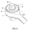
- a ratchet tool according to the present invention is shown to comprise a tool head 1, a drive body 2, a ratchet-and-pawl assembly 3, an actuator 4, and a releasably retaining unit 5.
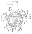
- the tool head 1 has an inner peripheral surface 11 which surrounds a rotating axis (X), and which defines an accommodation space 10.
- a plurality of ratchet teeth 111 are disposed on the inner peripheral surface 11.
- the ratchet teeth 111 are integrally formed with the inner peripheral surface 11.
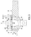
- the drive body 2 is rotatably received in the accommodation space 10 about the rotating axis (X), and has an outer surrounding surface 20 which surrounds the rotating axis (X), and which confronts the ratchet teeth 111, and a body major wall surface 21 facing along the rotating axis (X).
- the body major wall surface 21 has two guiding slots 22 which are disposed in symmetry to each other relative to the rotating axis (X), and each of which extends through the outer surrounding surface 20 to form two ports 221 thereat, and a receiving hole 23 extending in a direction of the rotating axis (X).
- the drive body 2 further includes a mounting post 24 extending from the body major wall surface 21 along the rotating axis (X).
- the ratchet-and-pawl assembly 3 includes first and second pawls 31, 32 and a first biasing member 33 disposed in one of the guiding slots 22, and third and fourth pawls 31, 32 and a second biasing member 33 disposed in the other one of the guiding slots 22.
- Each of the first, second, third and fourth pawls 31, 32 includes a guided body 310, 320 and a key 313, 323.
- the guided body 310, 320 is fitted in and is movable relative to the respective guiding slot 22, and extends toward the ratchet teeth 111 to terminate at a pawl end 311, 321 such that the guided body 310, 320 is displaceable between an extending position, where the pawl end 311, 321 extends through the respectively port 221 and is engaged with one ratchet tooth 111, and a retracted position, where the pawl end 311, 321 is retracted in the respective guiding slot 22 and is disengaged from the ratchet tooth 111.
- the key 313, 323 extends from the guided body 310, 320 in the direction of the rotating axis (X) and outwardly of the body major wall surface 21.
- the first and second biasing members 33 are disposed between the first and second pawls 31, 32 and between the third and fourth pawls 31, 32, respectively, so as to bias the guided bodies 310, 320 of each pawl 31, 32 toward the extending position.
- the actuator 4 is disposed on the body major wall surface 21 to be twistable relative to the tool head 1 about the rotating axis (X).
- the actuator 4 includes an actuator major wall 41 having an inner major wall surface 411 which confronts the accommodation space 10, and an outer major wall surface 412 opposite to the inner major wall surface 411, and a rim 42 extending from a marginal area of the outermajor wall surface 412 in the direction of the rotating axis (X).
- the inner major wall surface 411 has a central opening 45 to permit the actuator 4 to be sleeved on the mounting post 24.
- the inner major wall surface 411 has four inner boundary contours 43 which define four recessed regions 430 extending through the outer major wall surface 412. Each of the recessed regions 430 has proximate and distal segments 432, 431 angularly displaced from each other about the rotating axis (X).
- the releasably retaining unit 5 includes three positioning recesses 441, 442, 443 formed in the inner major wall surface 411 and angularly displaced from one another, and a spring-loaded ball 51 received in the receiving hole 23 and urged to engage a selected one of the positioning recesses 441, 442, 443.
- a cap 53 is disposed on the outer major wall surface 412 of the actuator 4 and is retained thereon by a C-shaped hoop 54.
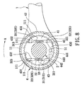
- the second preferred embodiment of a ratchet tool is similar to the previous embodiment in construction, except that the drive body 2 has three guiding slots 22 arranged around the rotating axis (X), and the ratchet-and-pawl assembly 3 further includes fifth and sixth pawls 31, 32 and a third biasing member 33 disposed in the third guiding slot 22 and having the same configuration as the first and second pawls 31, 32 and the first biasing member 33.
- At least three pawl ends 311, 321 are engaged with the ratchet teeth 111 during rotation of the tool head 1 when the actuator 4 is in any one of the midway, forward-direction and backward-direction positions, thereby reinforcing the structural strength of the ratchet tool and permitting transmission of even much larger torque.
- the third and fourth preferred embodiments of a ratchet tool according to this invention are similar to the first preferred embodiment.
- the recessed regions 430 are in the form of recesses formed in the inner major wall surface 411 and have cover surfaces 433 such that a cap 53 can be di spensed with.
- the recessed regions 430 are formed in the rim 42 of the actuator 4.
- the fifth preferred embodiment of a ratchet tool is similar to the first preferred embodiment in construction.
- the guided bodies 310, 320 of the first and second pawls 31, 32 respectively have first and second stage portions 314, 324 which extend toward and which are slidably interengaged with each other.
- the second stage portion 324 is disposed under the biasing member 33 to permit the biasing member 33 to rest thereon so as to stabilize the biasing action of the biasing member 33.
- the distance between the first and second pawls 31, 32 (and between the third and fourth pawls 31, 32) can be shortened without affecting of the biasing action of the biasing member 33, thereby rendering the ratchet tool more compact.
Landscapes
- Engineering & Computer Science (AREA)
- Mechanical Engineering (AREA)
- Portable Nailing Machines And Staplers (AREA)
- Details Of Spanners, Wrenches, And Screw Drivers And Accessories (AREA)
- Transmission Devices (AREA)
Applications Claiming Priority (1)
| Application Number | Priority Date | Filing Date | Title |
|---|---|---|---|
| TW099112871A TW201136716A (en) | 2010-04-23 | 2010-04-23 | Ratchet detent device |
Publications (2)
| Publication Number | Publication Date |
|---|---|
| EP2380703A2 true EP2380703A2 (de) | 2011-10-26 |
| EP2380703A3 EP2380703A3 (de) | 2015-07-22 |
Family
ID=44046749
Family Applications (1)
| Application Number | Title | Priority Date | Filing Date |
|---|---|---|---|
| EP10174712.9A Withdrawn EP2380703A3 (de) | 2010-04-23 | 2010-08-31 | Ratschenwerkzeug |
Country Status (3)
| Country | Link |
|---|---|
| US (1) | US8490521B2 (de) |
| EP (1) | EP2380703A3 (de) |
| TW (1) | TW201136716A (de) |
Families Citing this family (7)
| Publication number | Priority date | Publication date | Assignee | Title |
|---|---|---|---|---|
| CN102019596A (zh) * | 2011-01-12 | 2011-04-20 | 忻明良 | 棘轮扳手 |
| US8806985B2 (en) * | 2012-06-04 | 2014-08-19 | Bo-Shen CHEN | Reversing device for a ratchet wrench |
| TWI473688B (zh) * | 2013-02-08 | 2015-02-21 | Kabo Tool Co | 雙向棘輪結構、扳手及換向方法 |
| US20160288302A1 (en) * | 2015-04-02 | 2016-10-06 | Wheelfloat, Inc. | Ratchet Mechanism |
| TWI624334B (zh) * | 2017-07-14 | 2018-05-21 | Kuani Gear Co Ltd | Pneumatic tool safety switch button |
| TWI696522B (zh) * | 2019-01-31 | 2020-06-21 | 岡鼎金屬工業有限公司 | 棘動工具 |
| WO2023184132A1 (zh) * | 2022-03-29 | 2023-10-05 | 杭州巨星科技股份有限公司 | 一种棘轮机构及手动工具 |
Family Cites Families (7)
| Publication number | Priority date | Publication date | Assignee | Title |
|---|---|---|---|---|
| US2395681A (en) * | 1944-11-08 | 1946-02-26 | Duro Metal Prod Co | Ratchet mechanism |
| US3290969A (en) * | 1964-03-20 | 1966-12-13 | Pendleton Tool Ind Inc | Reversible ratchet wrench having linear sliding manually actuated pawls |
| US3621739A (en) * | 1970-07-24 | 1971-11-23 | Wendell Seablom | Reversible tool drive |
| US6053077A (en) * | 1998-08-10 | 2000-04-25 | Huang; Yung Hsu | Ratchet wrench having two driving stems |
| US6817458B1 (en) * | 2002-01-16 | 2004-11-16 | Michael T. Gauthier | Ratcheting mechanism |
| US6644147B1 (en) * | 2002-08-23 | 2003-11-11 | Chin-Tan Huang | Ratchet device for a screwdriver |
| US7380482B1 (en) * | 2007-03-06 | 2008-06-03 | Fu-Yi Chan | High-strength ratchet structure for ratchet wrench |
-
2010
- 2010-04-23 TW TW099112871A patent/TW201136716A/zh not_active IP Right Cessation
- 2010-08-31 EP EP10174712.9A patent/EP2380703A3/de not_active Withdrawn
- 2010-09-01 US US12/873,859 patent/US8490521B2/en not_active Expired - Fee Related
Also Published As
| Publication number | Publication date |
|---|---|
| TWI369276B (de) | 2012-08-01 |
| US8490521B2 (en) | 2013-07-23 |
| US20110259157A1 (en) | 2011-10-27 |
| EP2380703A3 (de) | 2015-07-22 |
| TW201136716A (en) | 2011-11-01 |
Similar Documents
| Publication | Publication Date | Title |
|---|---|---|
| EP2380703A2 (de) | Ratschenwerkzeug | |
| US9511484B2 (en) | Ratcheting screwdriver | |
| EP3352934B1 (de) | Spannfutter mit verriegelungsvorrichtung | |
| US6935211B2 (en) | Ratchet tool having improved driving shank | |
| US8210072B2 (en) | Roller bearing ratchet tool | |
| US8468914B2 (en) | Variable gear ratio ratchet | |
| US6450067B1 (en) | Ratchet driving tool | |
| US8931375B2 (en) | Ratchet device | |
| CN105082042A (zh) | 用于棘轮扳手的棘轮机构 | |
| US11794318B2 (en) | Shaft securing mechanism for a tool | |
| CA2637434C (en) | Three-way ratchet drive mechanism | |
| US20160121465A1 (en) | Variable Gear Ratio Ratchet | |
| EP4392206B1 (de) | Anordnung für ein elektrowerkzeug, frontteilbefestigung und elektrowerkzeug | |
| EP2543904A2 (de) | Kupplung, die zur Kraftübertragung in einer ausgewählten von zwei Richtungen in der Lage ist | |
| EP2476515B1 (de) | Ratschenschlüssel mit reduziertem Kopf | |
| EP2737977A1 (de) | In einer Richtung wirkender Ratschenschlüssel | |
| CA2549989A1 (en) | Screwdriver with ratchet mechanism | |
| US20160346907A1 (en) | Ratchet tool device | |
| US7028587B1 (en) | Ratchet tool | |
| EP3703908B1 (de) | Verbesserter achsensicherungsmechanismus für ein werkzeug | |
| EP4559624A1 (de) | Verbesserter ratschenmechanismus für ein werkzeug |
Legal Events
| Date | Code | Title | Description |
|---|---|---|---|
| AK | Designated contracting states |
Kind code of ref document: A2 Designated state(s): AL AT BE BG CH CY CZ DE DK EE ES FI FR GB GR HR HU IE IS IT LI LT LU LV MC MK MT NL NO PL PT RO SE SI SK SM TR |
|
| AX | Request for extension of the european patent |
Extension state: BA ME RS |
|
| PUAI | Public reference made under article 153(3) epc to a published international application that has entered the european phase |
Free format text: ORIGINAL CODE: 0009012 |
|
| PUAL | Search report despatched |
Free format text: ORIGINAL CODE: 0009013 |
|
| AK | Designated contracting states |
Kind code of ref document: A3 Designated state(s): AL AT BE BG CH CY CZ DE DK EE ES FI FR GB GR HR HU IE IS IT LI LT LU LV MC MK MT NL NO PL PT RO SE SI SK SM TR |
|
| AX | Request for extension of the european patent |
Extension state: BA ME RS |
|
| RIC1 | Information provided on ipc code assigned before grant |
Ipc: B25B 13/46 20060101AFI20150615BHEP |
|
| STAA | Information on the status of an ep patent application or granted ep patent |
Free format text: STATUS: THE APPLICATION IS DEEMED TO BE WITHDRAWN |
|
| 18D | Application deemed to be withdrawn |
Effective date: 20160123 |