EP2380728B1 - Reifenaufbauverfahren mittels einer Reifenwickeltrommel - Google Patents
Reifenaufbauverfahren mittels einer Reifenwickeltrommel Download PDFInfo
- Publication number
- EP2380728B1 EP2380728B1 EP20110163306 EP11163306A EP2380728B1 EP 2380728 B1 EP2380728 B1 EP 2380728B1 EP 20110163306 EP20110163306 EP 20110163306 EP 11163306 A EP11163306 A EP 11163306A EP 2380728 B1 EP2380728 B1 EP 2380728B1
- Authority
- EP
- European Patent Office
- Prior art keywords
- carcass
- building drum
- building
- centre section
- tread
- Prior art date
- Legal status (The legal status is an assumption and is not a legal conclusion. Google has not performed a legal analysis and makes no representation as to the accuracy of the status listed.)
- Not-in-force
Links
- 238000000034 method Methods 0.000 title claims description 19
- 239000011324 bead Substances 0.000 claims description 32
- 241000254043 Melolonthinae Species 0.000 claims description 5
- 238000005299 abrasion Methods 0.000 description 5
- 238000004519 manufacturing process Methods 0.000 description 3
- 238000010276 construction Methods 0.000 description 2
- 230000008602 contraction Effects 0.000 description 2
- 229920001875 Ebonite Polymers 0.000 description 1
- 239000004677 Nylon Substances 0.000 description 1
- 239000003795 chemical substances by application Substances 0.000 description 1
- 239000000945 filler Substances 0.000 description 1
- 239000002184 metal Substances 0.000 description 1
- 229920001778 nylon Polymers 0.000 description 1
- 230000003014 reinforcing effect Effects 0.000 description 1
- 230000000717 retained effect Effects 0.000 description 1
- 238000005728 strengthening Methods 0.000 description 1
Images


Classifications
-
- B—PERFORMING OPERATIONS; TRANSPORTING
- B29—WORKING OF PLASTICS; WORKING OF SUBSTANCES IN A PLASTIC STATE IN GENERAL
- B29D—PRODUCING PARTICULAR ARTICLES FROM PLASTICS OR FROM SUBSTANCES IN A PLASTIC STATE
- B29D30/00—Producing pneumatic or solid tyres or parts thereof
- B29D30/06—Pneumatic tyres or parts thereof (e.g. produced by casting, moulding, compression moulding, injection moulding, centrifugal casting)
- B29D30/08—Building tyres
- B29D30/20—Building tyres by the flat-tyre method, i.e. building on cylindrical drums
-
- B—PERFORMING OPERATIONS; TRANSPORTING
- B29—WORKING OF PLASTICS; WORKING OF SUBSTANCES IN A PLASTIC STATE IN GENERAL
- B29D—PRODUCING PARTICULAR ARTICLES FROM PLASTICS OR FROM SUBSTANCES IN A PLASTIC STATE
- B29D30/00—Producing pneumatic or solid tyres or parts thereof
- B29D30/06—Pneumatic tyres or parts thereof (e.g. produced by casting, moulding, compression moulding, injection moulding, centrifugal casting)
- B29D30/36—Expansion of tyres in a flat form, i.e. expansion to a toroidal shape independently of their building-up process, e.g. of tyres built by the flat-tyres method or by jointly covering two bead-rings
-
- B—PERFORMING OPERATIONS; TRANSPORTING
- B29—WORKING OF PLASTICS; WORKING OF SUBSTANCES IN A PLASTIC STATE IN GENERAL
- B29D—PRODUCING PARTICULAR ARTICLES FROM PLASTICS OR FROM SUBSTANCES IN A PLASTIC STATE
- B29D30/00—Producing pneumatic or solid tyres or parts thereof
- B29D30/06—Pneumatic tyres or parts thereof (e.g. produced by casting, moulding, compression moulding, injection moulding, centrifugal casting)
- B29D30/72—Side-walls
Definitions
- the present invention relates to a tyre building method using one building drum.
- a tyre comprises a toroidal carcass, which comprises a partly turned-up body ply and two annular beads, and supports an annular tread.
- a tread belt comprising a number of superimposed tread plies is interposed between the carcass and the tread; and an innerliner, impermeable to air, is placed inside the body ply to retain the air inside the tyre and maintain its inflation pressure.
- the body On the outside, the body ply supports two sidewalls, between the tread and the beads; and two abrasion gum strips below the sidewalls, at the beads.
- a so-called 'envelope' tyre structure is now commonly used, in which the width of the body ply is increased, so each lateral end of the body ply is located beneath the tread belt (and therefore beneath the tread), and the body ply, being superimposed on itself, is twice as thick along the full height of the sidewalls, thus greatly increasing the rigidity of the tyre with only a small increase in total weight.
- the envelope structure can be produced in either 'tread over sidewall' mode, in which each sidewall is inserted beneath the tread; or in 'sidewall over tread' mode, in which each sidewall is placed over the tread.
- the envelope structure can be produced in 'tread over sidewall' mode on one single-stage building drum, which allows for making one turn-up of both the body ply and the sidewalls before the tread belt and the tread are applied.
- 'sidewall over tread' mode which, to fold the body ply beneath the tread belt without inserting the sidewalls beneath the tread, calls for first turning up the body ply, and then the sidewalls, using two separate building drums.
- Patent application EP0302935Al represents the closest prior art and discloses a tyre building method using one single-stage building drum for building a radial tyre for aircraft having a inner carcass ply and a pair of side carcass plies, each of which is arranged between the inner carcass ply and a sidewall.
- Number 1 in Figure 1 indicates as a whole a tyre comprising a toroidal carcass 2, which comprises a single body ply 3 turned up partly on itself and so having two superimposed lateral layers.
- Two annular beads 4 are located on opposite sides of carcass 2, and are each enclosed by body ply 3 and have a bead core 5 reinforced with a number of turns of metal wire, and a bead filler 6.
- Carcass 2 supports an annular tread 7; a tread belt 8 comprising two tread plies 9 is interposed between carcass 2 and tread 7; and each tread ply 9 comprises a number of cords (not shown), which are embedded in a rubber strip, are arranged side by side with a given spacing, and are inclined at a given angle to the equatorial plane of tyre 1.
- a reinforcing layer 10, known as a 'cap ply', is provided on top of tread belt 8 (i.e. between tread belt 8 and tread 7), and is made from a continuous green-rubber strip reinforced internally with nylon threads or similar, and which is wound longitudinally (i.e. transversely and about the central axis of tyre 1) on top of tread belt 8 to protect and retain tread plies 9.
- tread ply inserts Two rubber inserts 11, known as tread ply inserts, are interposed between body ply 3 and the outer ends of tread belt 8 to act as a cushion.
- Two opposite lateral ends of body ply 3 are located beneath tread belt 8, close to and further inwards than the inner sides (i.e. the sides facing the centre of tyre 1) of tread ply inserts 11, to form an envelope structure of tyre 1.
- An innerliner 12 impermeable to air, is placed inside body ply 3 to retain the air inside and maintain the inflation pressure of tyre 1.
- body ply 3 supports two sidewalls 13, between tread 7 and beads 4.
- sidewalls 13 are located over tread 7, which means tyre 1 is produced in 'sidewall over tread' mode.
- Each sidewall 13 comprises an outer portion 14 made from a soft rubber mix highly resistant to the external agents (air and sunlight); and an abrasion gum strip 15 made from a hard rubber mix highly resistant to abrasion (when tyre 1 is mounted on the wheel rim, abrasion gum strips 15 are positioned contacting the edges of the rim).
- Outer portion 14 and abrasion gum strip 15 are normally extruded together to form sidewall 13.
- Each bead 4 is enclosed in a canvas chafer 16 for strengthening the bead 4 area and protecting bead core 5.
- Number 17 in Figure 2 indicates as a whole a single-stage building drum of the type described in Patent Applications EP1820628A2 and EP2008798A1 , which are included herein by way of reference.
- Building drum 17 is mounted on a central shaft (not shown) mounted to rotate about a longitudinal axis of rotation 18, and comprises a centre section 19 expandable and contractable both radially (i.e. perpendicular to axis of rotation 18, to adjust its outside diameter) and axially (i.e. parallel to axis of rotation 18, to adjust its length); and two lateral sections 20 located on opposite sides of centre section 19 and movable axially (i.e. parallel to axis of rotation 18) to accompany axial expansion or contraction of centre section 19 (i.e. the axial movement of lateral sections 20 is always coordinated with axial expansion or contraction of centre section 19).
- Building drum 17 comprises two specularly identical half-drums movable axially to and from each other (i.e. parallel to longitudinal axis of rotation 18). More specifically, each half-drum is mounted on a slide to move axially with respect to the central shaft, under the control of a pneumatic actuator, and supports a respective lateral section 20 and respective half of centre section 19, so that axial movement of the two half-drums expands or contracts centre section 19 axially.
- Each lateral section 20 has a bead locking device 21 expandable and contractable radially (i.e. perpendicular to longitudinal axis of rotation 18) with respect to lateral section 20; and a bladder 22, which is inflated with compressed air to follow the turn-up operations.
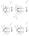
- a first turn-up is made to turn body ply 3, together with innerliner 12 and canvas chafers 16, outwardly up about beads 4 to form carcass 2 of tyre 1.
- bladders 22 are inflated and, at the same time, building drum 17 is contracted axially (i.e. lateral sections 20 are moved axially closer together, and centre section 19 is contracted axially).
- building drum 17 i.e. centre section 19 of building drum 17
- bead locking devices 21 are expanded radially to lock body ply 3 against beads 4 and prevent it from slipping with respect to beads 4 when making the first turn-up.
- tread belt 8, cap ply 10, and tread 7 are applied successively to carcass 2.
- pressure rollers 23 are rolled along the ends of tread 7 to press the ends of tread 7 firmly against carcass 2 underneath.
- Carcass 2 is removed axially off building drum 17 using an annular gripping member 24, which expands and contracts radially between a release position, in which the inside diameter of annular gripping member 24 is much larger than the outside diameter of carcass 2, and a grip position, in which the inside diameter of annular gripping member 24 substantially equals the outside diameter of carcass 2 (more specifically, in the grip position, annular gripping member 24 exerts a given pressure on carcass 2 to grip it firmly).
- annular gripping member 24 which expands and contracts radially between a release position, in which the inside diameter of annular gripping member 24 is much larger than the outside diameter of carcass 2, and a grip position, in which the inside diameter of annular gripping member 24 substantially equals the outside diameter of carcass 2 (more specifically, in the grip position, annular gripping member 24 exerts a given pressure on carcass 2 to grip it firmly).
- Annular gripping member 24 (expanded radially into the release position) is first placed about building drum 17 and carcass 2; is then contracted radially about carcass 2 into the grip position gripping carcass 2; and, finally, is withdrawn axially from building drum 17, taking carcass 2 with it and so also removing carcass 2 axially from building drum 17.
- annular gripping member 24 still holding carcass 2 is moved axially to move carcass 2 axially back into position about building drum 17.
- building drum 17 contracts axially (i.e. lateral sections 20 of building drum 17 move axially closer together, and centre section 19 of building drum 17 contracts axially) to position sidewalls 13 partly beneath carcass 2 (i.e. to position carcass 2 partly over sidewalls 13).
- building drum 17 i.e. centre section 19 of building drum 17 expands radially to insert centre section 19 partly inside carcass 2, which at this stage is still engaged by annular gripping member 24.
- bead locking devices 21 are expanded radially to lock sidewalls 13 to carcass 2 at beads 4.
- annular gripping member 24 is expanded radially to release carcass 2, and is then removed axially from building drum 17 to allow the second turn-up to be made.
- annular gripping member 24 may be expanded radially to release carcass 2, and then removed axially from building drum 17 after carcass 2 is centred axially with respect to building drum 17, and before bead locking devices 21 are expanded radially, or after centre section 19 of building drum 17 is expanded radially, and before carcass 2 is centred axially with respect to building drum 17.
- the tyre building method described therefore provides for producing tyre 1 (i.e. an envelope tyre in 'sidewall over tread' mode) using a single-stage building drum 17 forming part of a unistage machine.
Landscapes
- Engineering & Computer Science (AREA)
- Mechanical Engineering (AREA)
- Tyre Moulding (AREA)
Claims (10)
- Ein Aufbauverfahren zur Aufbauen eines Reifens (1) mit einer Hüllstruktur in einer "Seitenwand-über-Lauffläche"-Art, in welchem zwei gegenüberliegende laterale Enden einer Körperlage (3) unterhalb eines Laufflächenbandes (8) positioniert sind, und die Seitenwände (13) über einer Lauffläche (7) angeordnet sind; wobei der Reifen (1) unter Verwendung einer Aufbautrommel (17) aufgebaut ist, welche einen Zentralabschnitt (19) und zwei laterale Abschnitte (20) auf gegenüberliegenden Seiten des Zentralabschnitts (19) aufweist; wobei das Aufbauverfahren die folgenden Schritte aufweist:Anordnen eines Innenliners (12), der Körperlage (3) und zweier Wülste (4) um die Aufbautrommel (17);Ausführen eines ersten Umschlagens, um die Körperlage (3) nach außen hoch um die Wülste (4) umzuschlagen, um eine Karkasse (2) des Reifens (1) zu bilden;Aufbringen eines Laufflächenbandes (8) und einer Lauffläche (7) auf die Karkasse (2) und über die zwei gegenüberliegenden lateralen Enden der Körperlage (3); undEntfernen der Karkasse (2) aus der Aufbautrommel (17);wobei das Aufbauverfahren dadurch gekennzeichnet ist, dass es die weiteren Schritte aufweist:Anordnen zweier Seitenwände (13) um dieselbe Aufbautrommel (17);Wiederanordnen der Karkasse (2) um die Aufbautrommel (17) und teilweise über die Seitenwände (13); undAusführen eines zweiten Umschlagens, um die Seitenwände (13) nach außen hoch um die Karkasse (2) und über die Lauffläche (7) umzuschlagen.
- Aufbauverfahren nach Anspruch 1, und die weiteren folgenden Schritte aufweisend:simultanes radiales Ausdehnen und axiales Zusammenziehen der Aufbautrommel (17), wenn das erste Umschlagen durchgeführt wird; undsimultanes radiales Zusammenziehen und axiales Ausdehnen der Aufbautrommel (17) nach dem Aufbringen des Laufflächenbandes (8) und der Lauffläche (7) auf die Karkasse (2), und vor dem Entfernen der Kasse (2) aus der Aufbautrommel (17).
- Aufbauverfahren nach Anspruch 1 oder 2, wobei der Schritt des Entfernens der Karkasse (2) aus der Aufbautrommel (17) die weiteren folgenden Schritte aufweist:Anordnen eines ringförmigen Greifbauteils (24) um die Karkasse (2) auf der Aufbautrommel (17);Greifen der Karkasse (2) mittels des ringförmigen Greifbauteils (24) und durch radiales Zusammendrücken des ringförmigen Greifbauteils (24) um die Karkasse (2); undEntfernen der Karkasse (2) aus der Aufbautrommel (17) durch axiales Bewegen des ringförmigen Greifbauteils (24), welches die Karkasse (2) greift.
- Aufbauverfahren nach Anspruch 3, wobei der Schritt des Wiederanordnens der Karkasse (2) um die Aufbautrommel (17) die weiteren folgenden Schritte aufweist:Anordnen der Karkasse (2) um die Aufbautrommel (17) durch axiales Bewegen des ringförmigen Greifbauteils (24), welches die Karkasse (2) greift;simultanes radiales Ausdehnen und axiales Zusammenziehen des Zentralabschnitts (19) der Aufbautrommel (17), um den Zentralabschnitt (19) der Aufbautrommel (17) teilweise in die Karkasse (2) einzufügen; undFreigeben der Karkasse (2) aus dem ringförmigen Greifbauteil (24) durch radiales Ausdehnen des ringförmigen Greifbauteils (24) nach dem teilweisen Einfügen des Zentralabschnitts (19) der Aufbautrommel (17) in die Karkasse (2).
- Aufbauverfahren nach Anspruch 4, und weiterhin den Schritt eines radialen Ausdehnens des Zentralabschnitts (19) der Aufbautrommel (17) aufweisend, um den Zentralabschnitt (19) der Aufbautrommel (17) gegen die Wülste (4) zu drücken, nach dem teilweisen Einfügen des Zentralabschnitts (19) der Aufbautrommel (17) in die Karkasse (2) und vor dem Ausführen des zweiten Umschlagens.
- Aufbauverfahren nach Anspruch 5, und weiterhin den Schritt eines Freigebens der Karkasse (2) aus dem ringförmigen Greifbauteil (24) durch radiales Ausdehnen des ringförmigen Greifbauteils (24) nach dem radialen Ausdehnen des Zentralabschnitts (19) der Aufbautrommel (17) aufweisend, um die Aufbautrommel (17) gegen die Wülste (4) zu drücken.
- Aufbauverfahren nach irgendeinem der Ansprüche 1 bis 6, und den weiteren Schritt eines simultanen radialen Ausdehnens und axialen Zusammenziehens des Zentralabschnitts (19) der Aufbautrommel (17) aufweisend, um den Zentralabschnitt (19) der Aufbautrommel (17) teilweise in die Karkasse (2) einzufügen, bevor das zweite Umschlagen ausgeführt wird.
- Aufbauverfahren nach Anspruch 7, und den weiteren Schritt eines radialen Ausdehnens des Zentralabschnitts (19) der Aufbautrommel (17) aufweisend, um den Zentralabschnitt (19) der Aufbautrommel (17) gegen die Wülste (4) zu drücken, nachdem der Zentralabschnitt (19) der Aufbautrommel (17) teilweise in die Karkasse (2) eingefügt wird, und bevor das zweite Umschlagen ausgeführt wird.
- Aufbauverfahren nach irgendeinem der Ansprüche 1 bis 8, und den weiteren Schritt eines radialen Ausdehnens von Wulstsperrvorrichtungen (21) aufweisend, um die Seitenwände (13) gegen die Karkasse (2) an den Wülsten (4) zu sperren, bevor das zweite Umschlagen ausgeführt wird.
- Aufbauverfahren nach irgendeinem der Ansprüche 1 bis 9, und den weiteren Schritt eines Anordnens um die Aufbautrommel (17) von zwei Wulstschutzbändern (16) an dem Wulstbereich zusammen mit dem Innenliner (12), der Körperlage (3) und den zwei Wülsten (4) aufweisend.
Applications Claiming Priority (1)
| Application Number | Priority Date | Filing Date | Title |
|---|---|---|---|
| IT000323A ITTO20100323A1 (it) | 2010-04-20 | 2010-04-20 | Metodo di costruzione di un pneumatico mediante un unico tamburo di formatura |
Publications (2)
| Publication Number | Publication Date |
|---|---|
| EP2380728A1 EP2380728A1 (de) | 2011-10-26 |
| EP2380728B1 true EP2380728B1 (de) | 2013-08-21 |
Family
ID=43038004
Family Applications (1)
| Application Number | Title | Priority Date | Filing Date |
|---|---|---|---|
| EP20110163306 Not-in-force EP2380728B1 (de) | 2010-04-20 | 2011-04-20 | Reifenaufbauverfahren mittels einer Reifenwickeltrommel |
Country Status (3)
| Country | Link |
|---|---|
| EP (1) | EP2380728B1 (de) |
| ES (1) | ES2433002T3 (de) |
| IT (1) | ITTO20100323A1 (de) |
Cited By (3)
| Publication number | Priority date | Publication date | Assignee | Title |
|---|---|---|---|---|
| CN107073858A (zh) * | 2014-11-10 | 2017-08-18 | 住友橡胶工业株式会社 | 充气轮胎的制造方法和充气轮胎 |
| CN107073857A (zh) * | 2014-11-10 | 2017-08-18 | 住友橡胶工业株式会社 | 充气轮胎的制造方法和充气轮胎 |
| CN107148338A (zh) * | 2014-11-10 | 2017-09-08 | 住友橡胶工业株式会社 | 充气轮胎的制造方法和充气轮胎 |
Families Citing this family (7)
| Publication number | Priority date | Publication date | Assignee | Title |
|---|---|---|---|---|
| DE102011050458A1 (de) * | 2011-05-18 | 2012-11-22 | Continental Reifen Deutschland Gmbh | Verfahren zur Herstellung eines Fahrzeugreifens |
| DE102012112495A1 (de) * | 2012-12-18 | 2014-06-18 | Continental Reifen Deutschland Gmbh | Verfahren zur Herstellung eines Fahrzeugreifens |
| DE102013106027A1 (de) * | 2013-06-11 | 2014-12-24 | Continental Reifen Deutschland Gmbh | Verfahren zur Herstellung eines Fahrzeugreifens |
| MX2019007075A (es) * | 2016-12-29 | 2019-09-05 | Pirelli | Aparato y proceso para construir neumaticos para ruedas de vehiculo. |
| WO2019123200A1 (en) * | 2017-12-20 | 2019-06-27 | Bridgestone Europe Nv/Sa | Method for the production of a fabric for the manufacture of a ply of a pneumatic tyre and method for the construction of said pneumatic tyre |
| US20200198276A1 (en) * | 2018-12-20 | 2020-06-25 | The Goodyear Tire & Rubber Company | Method of building a tire with no bead turnup |
| DE102019119474A1 (de) * | 2019-07-18 | 2021-01-21 | Harburg-Freudenberger Maschinenbau Gmbh | Verfahren und Vorrichtung zur Herstellung von Reifenrohlingen |
Family Cites Families (4)
| Publication number | Priority date | Publication date | Assignee | Title |
|---|---|---|---|---|
| WO1987005865A1 (fr) * | 1986-03-31 | 1987-10-08 | Sumitomo Rubber Industries, Ltd. | Pneumatique radial pour aeronef et procede de production |
| US6783618B2 (en) * | 2000-12-22 | 2004-08-31 | Pirelli Pneumatici S.P.A. | Method and apparatus for the manufacturing of a tire for vehicle wheels |
| ITTO20060118A1 (it) | 2006-02-21 | 2007-08-22 | Bridgestone Corp | Tamburo di formatura di pneumatici |
| ITTO20070465A1 (it) | 2007-06-27 | 2008-12-28 | Bridgestone Corp | Tamburo di formatura di pneumatici |
-
2010
- 2010-04-20 IT IT000323A patent/ITTO20100323A1/it unknown
-
2011
- 2011-04-20 ES ES11163306T patent/ES2433002T3/es active Active
- 2011-04-20 EP EP20110163306 patent/EP2380728B1/de not_active Not-in-force
Cited By (5)
| Publication number | Priority date | Publication date | Assignee | Title |
|---|---|---|---|---|
| CN107073858A (zh) * | 2014-11-10 | 2017-08-18 | 住友橡胶工业株式会社 | 充气轮胎的制造方法和充气轮胎 |
| CN107073857A (zh) * | 2014-11-10 | 2017-08-18 | 住友橡胶工业株式会社 | 充气轮胎的制造方法和充气轮胎 |
| CN107148338A (zh) * | 2014-11-10 | 2017-09-08 | 住友橡胶工业株式会社 | 充气轮胎的制造方法和充气轮胎 |
| CN107148338B (zh) * | 2014-11-10 | 2019-05-03 | 住友橡胶工业株式会社 | 充气轮胎的制造方法 |
| US10538047B2 (en) | 2014-11-10 | 2020-01-21 | Sumitomo Rubber Industries, Ltd. | Pneumatic tire manufacturing method, and pneumatic tire |
Also Published As
| Publication number | Publication date |
|---|---|
| ITTO20100323A1 (it) | 2011-10-21 |
| EP2380728A1 (de) | 2011-10-26 |
| ES2433002T3 (es) | 2013-12-05 |
Similar Documents
| Publication | Publication Date | Title |
|---|---|---|
| EP2380728B1 (de) | Reifenaufbauverfahren mittels einer Reifenwickeltrommel | |
| EP2111334B1 (de) | Verfahren und vorrichtung zur herstellung von reifen | |
| US20230278303A1 (en) | Tyre for vehicle wheels | |
| EP1504883B1 (de) | Eine einen hohen Scheitel aufweisende Aufbautrommel zur Herstellung einer erststufigen Karkasse | |
| US20150059962A1 (en) | Method of building a tire | |
| EP2845721B1 (de) | Reifenaufbautrommel und Verfahren zur Herstellung eines Reifens | |
| US20150059984A1 (en) | Tire building drum | |
| US20130206321A1 (en) | Method and assembly for manufacturing a green tyre | |
| US10792876B2 (en) | Process and apparatus for building tyres | |
| US4072550A (en) | Method and apparatus for building a closed torus tire | |
| CN109421304B (zh) | 制造轮胎的方法 | |
| CN109501345A (zh) | 一种轮胎成型机的成型方法 | |
| CN100441404C (zh) | 用于制造车轮充气轮胎的方法和设备 | |
| EP1556207B1 (de) | Verfahren und vorrichtung zur herstellung eines fahrzeugreifens | |
| KR20050083818A (ko) | 차륜용 공기압 타이어 제조방법 및 제조장치 | |
| KR20050083817A (ko) | 차륜용 공기압 타이어 제조방법 및 제조장치 |
Legal Events
| Date | Code | Title | Description |
|---|---|---|---|
| AK | Designated contracting states |
Kind code of ref document: A1 Designated state(s): AL AT BE BG CH CY CZ DE DK EE ES FI FR GB GR HR HU IE IS IT LI LT LU LV MC MK MT NL NO PL PT RO RS SE SI SK SM TR |
|
| AX | Request for extension of the european patent |
Extension state: BA ME |
|
| PUAI | Public reference made under article 153(3) epc to a published international application that has entered the european phase |
Free format text: ORIGINAL CODE: 0009012 |
|
| 17P | Request for examination filed |
Effective date: 20120426 |
|
| GRAP | Despatch of communication of intention to grant a patent |
Free format text: ORIGINAL CODE: EPIDOSNIGR1 |
|
| GRAS | Grant fee paid |
Free format text: ORIGINAL CODE: EPIDOSNIGR3 |
|
| GRAA | (expected) grant |
Free format text: ORIGINAL CODE: 0009210 |
|
| AK | Designated contracting states |
Kind code of ref document: B1 Designated state(s): AL AT BE BG CH CY CZ DE DK EE ES FI FR GB GR HR HU IE IS IT LI LT LU LV MC MK MT NL NO PL PT RO RS SE SI SK SM TR |
|
| REG | Reference to a national code |
Ref country code: GB Ref legal event code: FG4D |
|
| REG | Reference to a national code |
Ref country code: CH Ref legal event code: EP |
|
| REG | Reference to a national code |
Ref country code: AT Ref legal event code: REF Ref document number: 627796 Country of ref document: AT Kind code of ref document: T Effective date: 20130915 |
|
| REG | Reference to a national code |
Ref country code: IE Ref legal event code: FG4D |
|
| REG | Reference to a national code |
Ref country code: DE Ref legal event code: R096 Ref document number: 602011002656 Country of ref document: DE Effective date: 20131017 |
|
| REG | Reference to a national code |
Ref country code: ES Ref legal event code: FG2A Ref document number: 2433002 Country of ref document: ES Kind code of ref document: T3 Effective date: 20131205 |
|
| REG | Reference to a national code |
Ref country code: NL Ref legal event code: VDEP Effective date: 20130821 Ref country code: AT Ref legal event code: MK05 Ref document number: 627796 Country of ref document: AT Kind code of ref document: T Effective date: 20130821 |
|
| REG | Reference to a national code |
Ref country code: LT Ref legal event code: MG4D |
|
| PG25 | Lapsed in a contracting state [announced via postgrant information from national office to epo] |
Ref country code: CY Free format text: LAPSE BECAUSE OF FAILURE TO SUBMIT A TRANSLATION OF THE DESCRIPTION OR TO PAY THE FEE WITHIN THE PRESCRIBED TIME-LIMIT Effective date: 20130724 Ref country code: SE Free format text: LAPSE BECAUSE OF FAILURE TO SUBMIT A TRANSLATION OF THE DESCRIPTION OR TO PAY THE FEE WITHIN THE PRESCRIBED TIME-LIMIT Effective date: 20130821 Ref country code: NO Free format text: LAPSE BECAUSE OF FAILURE TO SUBMIT A TRANSLATION OF THE DESCRIPTION OR TO PAY THE FEE WITHIN THE PRESCRIBED TIME-LIMIT Effective date: 20131121 Ref country code: IS Free format text: LAPSE BECAUSE OF FAILURE TO SUBMIT A TRANSLATION OF THE DESCRIPTION OR TO PAY THE FEE WITHIN THE PRESCRIBED TIME-LIMIT Effective date: 20131221 Ref country code: AT Free format text: LAPSE BECAUSE OF FAILURE TO SUBMIT A TRANSLATION OF THE DESCRIPTION OR TO PAY THE FEE WITHIN THE PRESCRIBED TIME-LIMIT Effective date: 20130821 Ref country code: PT Free format text: LAPSE BECAUSE OF FAILURE TO SUBMIT A TRANSLATION OF THE DESCRIPTION OR TO PAY THE FEE WITHIN THE PRESCRIBED TIME-LIMIT Effective date: 20131223 Ref country code: HR Free format text: LAPSE BECAUSE OF FAILURE TO SUBMIT A TRANSLATION OF THE DESCRIPTION OR TO PAY THE FEE WITHIN THE PRESCRIBED TIME-LIMIT Effective date: 20130821 Ref country code: LT Free format text: LAPSE BECAUSE OF FAILURE TO SUBMIT A TRANSLATION OF THE DESCRIPTION OR TO PAY THE FEE WITHIN THE PRESCRIBED TIME-LIMIT Effective date: 20130821 |
|
| PG25 | Lapsed in a contracting state [announced via postgrant information from national office to epo] |
Ref country code: PL Free format text: LAPSE BECAUSE OF FAILURE TO SUBMIT A TRANSLATION OF THE DESCRIPTION OR TO PAY THE FEE WITHIN THE PRESCRIBED TIME-LIMIT Effective date: 20130821 Ref country code: FI Free format text: LAPSE BECAUSE OF FAILURE TO SUBMIT A TRANSLATION OF THE DESCRIPTION OR TO PAY THE FEE WITHIN THE PRESCRIBED TIME-LIMIT Effective date: 20130821 Ref country code: LV Free format text: LAPSE BECAUSE OF FAILURE TO SUBMIT A TRANSLATION OF THE DESCRIPTION OR TO PAY THE FEE WITHIN THE PRESCRIBED TIME-LIMIT Effective date: 20130821 Ref country code: BE Free format text: LAPSE BECAUSE OF FAILURE TO SUBMIT A TRANSLATION OF THE DESCRIPTION OR TO PAY THE FEE WITHIN THE PRESCRIBED TIME-LIMIT Effective date: 20130821 Ref country code: SI Free format text: LAPSE BECAUSE OF FAILURE TO SUBMIT A TRANSLATION OF THE DESCRIPTION OR TO PAY THE FEE WITHIN THE PRESCRIBED TIME-LIMIT Effective date: 20130821 Ref country code: GR Free format text: LAPSE BECAUSE OF FAILURE TO SUBMIT A TRANSLATION OF THE DESCRIPTION OR TO PAY THE FEE WITHIN THE PRESCRIBED TIME-LIMIT Effective date: 20131122 |
|
| PG25 | Lapsed in a contracting state [announced via postgrant information from national office to epo] |
Ref country code: CY Free format text: LAPSE BECAUSE OF FAILURE TO SUBMIT A TRANSLATION OF THE DESCRIPTION OR TO PAY THE FEE WITHIN THE PRESCRIBED TIME-LIMIT Effective date: 20130821 |
|
| PG25 | Lapsed in a contracting state [announced via postgrant information from national office to epo] |
Ref country code: DK Free format text: LAPSE BECAUSE OF FAILURE TO SUBMIT A TRANSLATION OF THE DESCRIPTION OR TO PAY THE FEE WITHIN THE PRESCRIBED TIME-LIMIT Effective date: 20130821 Ref country code: SK Free format text: LAPSE BECAUSE OF FAILURE TO SUBMIT A TRANSLATION OF THE DESCRIPTION OR TO PAY THE FEE WITHIN THE PRESCRIBED TIME-LIMIT Effective date: 20130821 Ref country code: RO Free format text: LAPSE BECAUSE OF FAILURE TO SUBMIT A TRANSLATION OF THE DESCRIPTION OR TO PAY THE FEE WITHIN THE PRESCRIBED TIME-LIMIT Effective date: 20130821 Ref country code: CZ Free format text: LAPSE BECAUSE OF FAILURE TO SUBMIT A TRANSLATION OF THE DESCRIPTION OR TO PAY THE FEE WITHIN THE PRESCRIBED TIME-LIMIT Effective date: 20130821 Ref country code: EE Free format text: LAPSE BECAUSE OF FAILURE TO SUBMIT A TRANSLATION OF THE DESCRIPTION OR TO PAY THE FEE WITHIN THE PRESCRIBED TIME-LIMIT Effective date: 20130821 Ref country code: NL Free format text: LAPSE BECAUSE OF FAILURE TO SUBMIT A TRANSLATION OF THE DESCRIPTION OR TO PAY THE FEE WITHIN THE PRESCRIBED TIME-LIMIT Effective date: 20130821 |
|
| PLBE | No opposition filed within time limit |
Free format text: ORIGINAL CODE: 0009261 |
|
| STAA | Information on the status of an ep patent application or granted ep patent |
Free format text: STATUS: NO OPPOSITION FILED WITHIN TIME LIMIT |
|
| 26N | No opposition filed |
Effective date: 20140522 |
|
| PGFP | Annual fee paid to national office [announced via postgrant information from national office to epo] |
Ref country code: DE Payment date: 20140430 Year of fee payment: 4 Ref country code: ES Payment date: 20140411 Year of fee payment: 4 Ref country code: FR Payment date: 20140409 Year of fee payment: 4 Ref country code: IT Payment date: 20140430 Year of fee payment: 4 |
|
| REG | Reference to a national code |
Ref country code: DE Ref legal event code: R097 Ref document number: 602011002656 Country of ref document: DE Effective date: 20140522 |
|
| PG25 | Lapsed in a contracting state [announced via postgrant information from national office to epo] |
Ref country code: LU Free format text: LAPSE BECAUSE OF FAILURE TO SUBMIT A TRANSLATION OF THE DESCRIPTION OR TO PAY THE FEE WITHIN THE PRESCRIBED TIME-LIMIT Effective date: 20140420 Ref country code: MC Free format text: LAPSE BECAUSE OF FAILURE TO SUBMIT A TRANSLATION OF THE DESCRIPTION OR TO PAY THE FEE WITHIN THE PRESCRIBED TIME-LIMIT Effective date: 20130821 |
|
| REG | Reference to a national code |
Ref country code: CH Ref legal event code: PL |
|
| REG | Reference to a national code |
Ref country code: IE Ref legal event code: MM4A |
|
| PG25 | Lapsed in a contracting state [announced via postgrant information from national office to epo] |
Ref country code: LI Free format text: LAPSE BECAUSE OF NON-PAYMENT OF DUE FEES Effective date: 20140430 Ref country code: CH Free format text: LAPSE BECAUSE OF NON-PAYMENT OF DUE FEES Effective date: 20140430 |
|
| PG25 | Lapsed in a contracting state [announced via postgrant information from national office to epo] |
Ref country code: IE Free format text: LAPSE BECAUSE OF NON-PAYMENT OF DUE FEES Effective date: 20140420 |
|
| REG | Reference to a national code |
Ref country code: DE Ref legal event code: R119 Ref document number: 602011002656 Country of ref document: DE |
|
| GBPC | Gb: european patent ceased through non-payment of renewal fee |
Effective date: 20150420 |
|
| PG25 | Lapsed in a contracting state [announced via postgrant information from national office to epo] |
Ref country code: GB Free format text: LAPSE BECAUSE OF NON-PAYMENT OF DUE FEES Effective date: 20150420 Ref country code: IT Free format text: LAPSE BECAUSE OF NON-PAYMENT OF DUE FEES Effective date: 20150420 Ref country code: DE Free format text: LAPSE BECAUSE OF NON-PAYMENT OF DUE FEES Effective date: 20151103 |
|
| REG | Reference to a national code |
Ref country code: FR Ref legal event code: ST Effective date: 20151231 |
|
| PG25 | Lapsed in a contracting state [announced via postgrant information from national office to epo] |
Ref country code: FR Free format text: LAPSE BECAUSE OF NON-PAYMENT OF DUE FEES Effective date: 20150430 |
|
| PG25 | Lapsed in a contracting state [announced via postgrant information from national office to epo] |
Ref country code: MT Free format text: LAPSE BECAUSE OF FAILURE TO SUBMIT A TRANSLATION OF THE DESCRIPTION OR TO PAY THE FEE WITHIN THE PRESCRIBED TIME-LIMIT Effective date: 20130821 |
|
| PG25 | Lapsed in a contracting state [announced via postgrant information from national office to epo] |
Ref country code: SM Free format text: LAPSE BECAUSE OF FAILURE TO SUBMIT A TRANSLATION OF THE DESCRIPTION OR TO PAY THE FEE WITHIN THE PRESCRIBED TIME-LIMIT Effective date: 20130821 |
|
| REG | Reference to a national code |
Ref country code: ES Ref legal event code: FD2A Effective date: 20160526 |
|
| PG25 | Lapsed in a contracting state [announced via postgrant information from national office to epo] |
Ref country code: RS Free format text: LAPSE BECAUSE OF FAILURE TO SUBMIT A TRANSLATION OF THE DESCRIPTION OR TO PAY THE FEE WITHIN THE PRESCRIBED TIME-LIMIT Effective date: 20130821 Ref country code: BG Free format text: LAPSE BECAUSE OF FAILURE TO SUBMIT A TRANSLATION OF THE DESCRIPTION OR TO PAY THE FEE WITHIN THE PRESCRIBED TIME-LIMIT Effective date: 20130821 |
|
| PG25 | Lapsed in a contracting state [announced via postgrant information from national office to epo] |
Ref country code: ES Free format text: LAPSE BECAUSE OF NON-PAYMENT OF DUE FEES Effective date: 20150421 Ref country code: HU Free format text: LAPSE BECAUSE OF FAILURE TO SUBMIT A TRANSLATION OF THE DESCRIPTION OR TO PAY THE FEE WITHIN THE PRESCRIBED TIME-LIMIT; INVALID AB INITIO Effective date: 20110420 Ref country code: TR Free format text: LAPSE BECAUSE OF FAILURE TO SUBMIT A TRANSLATION OF THE DESCRIPTION OR TO PAY THE FEE WITHIN THE PRESCRIBED TIME-LIMIT Effective date: 20130821 |
|
| PG25 | Lapsed in a contracting state [announced via postgrant information from national office to epo] |
Ref country code: MK Free format text: LAPSE BECAUSE OF FAILURE TO SUBMIT A TRANSLATION OF THE DESCRIPTION OR TO PAY THE FEE WITHIN THE PRESCRIBED TIME-LIMIT Effective date: 20130821 |
|
| PG25 | Lapsed in a contracting state [announced via postgrant information from national office to epo] |
Ref country code: AL Free format text: LAPSE BECAUSE OF FAILURE TO SUBMIT A TRANSLATION OF THE DESCRIPTION OR TO PAY THE FEE WITHIN THE PRESCRIBED TIME-LIMIT Effective date: 20130821 |