EP2380762A1 - Jambe de force de ressort et procédé de fabrication d'un composant d'une jambe de force de ressort - Google Patents
Jambe de force de ressort et procédé de fabrication d'un composant d'une jambe de force de ressort Download PDFInfo
- Publication number
- EP2380762A1 EP2380762A1 EP11161093A EP11161093A EP2380762A1 EP 2380762 A1 EP2380762 A1 EP 2380762A1 EP 11161093 A EP11161093 A EP 11161093A EP 11161093 A EP11161093 A EP 11161093A EP 2380762 A1 EP2380762 A1 EP 2380762A1
- Authority
- EP
- European Patent Office
- Prior art keywords
- bearing
- guide ring
- insulating layer
- strut bearing
- strut
- Prior art date
- Legal status (The legal status is an assumption and is not a legal conclusion. Google has not performed a legal analysis and makes no representation as to the accuracy of the status listed.)
- Withdrawn
Links
- 239000000725 suspension Substances 0.000 title claims abstract description 31
- 238000004519 manufacturing process Methods 0.000 title claims abstract description 15
- 230000002787 reinforcement Effects 0.000 claims abstract description 23
- 238000005096 rolling process Methods 0.000 claims abstract description 14
- 239000000463 material Substances 0.000 claims abstract description 11
- 239000004033 plastic Substances 0.000 claims abstract description 9
- 229920003023 plastic Polymers 0.000 claims abstract description 9
- 238000001746 injection moulding Methods 0.000 claims description 15
- 238000005538 encapsulation Methods 0.000 claims description 3
- 238000013016 damping Methods 0.000 abstract description 6
- 239000006096 absorbing agent Substances 0.000 description 14
- 230000035939 shock Effects 0.000 description 14
- 230000000694 effects Effects 0.000 description 5
- 238000002347 injection Methods 0.000 description 5
- 239000007924 injection Substances 0.000 description 5
- 238000000034 method Methods 0.000 description 5
- 238000000465 moulding Methods 0.000 description 4
- 239000002184 metal Substances 0.000 description 3
- 230000002093 peripheral effect Effects 0.000 description 3
- 230000003014 reinforcing effect Effects 0.000 description 3
- 238000010276 construction Methods 0.000 description 2
- 238000005516 engineering process Methods 0.000 description 2
- 238000009434 installation Methods 0.000 description 2
- 238000005304 joining Methods 0.000 description 2
- 229920003002 synthetic resin Polymers 0.000 description 2
- 239000000057 synthetic resin Substances 0.000 description 2
- 238000005452 bending Methods 0.000 description 1
- 230000008859 change Effects 0.000 description 1
- 230000006835 compression Effects 0.000 description 1
- 238000007906 compression Methods 0.000 description 1
- 229920001971 elastomer Polymers 0.000 description 1
- 239000000806 elastomer Substances 0.000 description 1
- 230000007246 mechanism Effects 0.000 description 1
- 238000012986 modification Methods 0.000 description 1
- 230000004048 modification Effects 0.000 description 1
- 230000008569 process Effects 0.000 description 1
- 229920005989 resin Polymers 0.000 description 1
- 239000011347 resin Substances 0.000 description 1
Images

Classifications
-
- B—PERFORMING OPERATIONS; TRANSPORTING
- B60—VEHICLES IN GENERAL
- B60G—VEHICLE SUSPENSION ARRANGEMENTS
- B60G15/00—Resilient suspensions characterised by arrangement, location or type of combined spring and vibration damper, e.g. telescopic type
- B60G15/02—Resilient suspensions characterised by arrangement, location or type of combined spring and vibration damper, e.g. telescopic type having mechanical spring
- B60G15/06—Resilient suspensions characterised by arrangement, location or type of combined spring and vibration damper, e.g. telescopic type having mechanical spring and fluid damper
- B60G15/067—Resilient suspensions characterised by arrangement, location or type of combined spring and vibration damper, e.g. telescopic type having mechanical spring and fluid damper characterised by the mounting on the vehicle body or chassis of the spring and damper unit
- B60G15/068—Resilient suspensions characterised by arrangement, location or type of combined spring and vibration damper, e.g. telescopic type having mechanical spring and fluid damper characterised by the mounting on the vehicle body or chassis of the spring and damper unit specially adapted for MacPherson strut-type suspension
-
- B—PERFORMING OPERATIONS; TRANSPORTING
- B60—VEHICLES IN GENERAL
- B60G—VEHICLE SUSPENSION ARRANGEMENTS
- B60G15/00—Resilient suspensions characterised by arrangement, location or type of combined spring and vibration damper, e.g. telescopic type
- B60G15/02—Resilient suspensions characterised by arrangement, location or type of combined spring and vibration damper, e.g. telescopic type having mechanical spring
- B60G15/06—Resilient suspensions characterised by arrangement, location or type of combined spring and vibration damper, e.g. telescopic type having mechanical spring and fluid damper
-
- F—MECHANICAL ENGINEERING; LIGHTING; HEATING; WEAPONS; BLASTING
- F16—ENGINEERING ELEMENTS AND UNITS; GENERAL MEASURES FOR PRODUCING AND MAINTAINING EFFECTIVE FUNCTIONING OF MACHINES OR INSTALLATIONS; THERMAL INSULATION IN GENERAL
- F16C—SHAFTS; FLEXIBLE SHAFTS; ELEMENTS OR CRANKSHAFT MECHANISMS; ROTARY BODIES OTHER THAN GEARING ELEMENTS; BEARINGS
- F16C19/00—Bearings with rolling contact, for exclusively rotary movement
- F16C19/02—Bearings with rolling contact, for exclusively rotary movement with bearing balls essentially of the same size in one or more circular rows
- F16C19/10—Bearings with rolling contact, for exclusively rotary movement with bearing balls essentially of the same size in one or more circular rows for axial load mainly
-
- B—PERFORMING OPERATIONS; TRANSPORTING
- B60—VEHICLES IN GENERAL
- B60G—VEHICLE SUSPENSION ARRANGEMENTS
- B60G2204/00—Indexing codes related to suspensions per se or to auxiliary parts
- B60G2204/10—Mounting of suspension elements
- B60G2204/12—Mounting of springs or dampers
- B60G2204/128—Damper mount on vehicle body or chassis
-
- B—PERFORMING OPERATIONS; TRANSPORTING
- B60—VEHICLES IN GENERAL
- B60G—VEHICLE SUSPENSION ARRANGEMENTS
- B60G2204/00—Indexing codes related to suspensions per se or to auxiliary parts
- B60G2204/40—Auxiliary suspension parts; Adjustment of suspensions
- B60G2204/418—Bearings, e.g. ball or roller bearings
-
- B—PERFORMING OPERATIONS; TRANSPORTING
- B60—VEHICLES IN GENERAL
- B60G—VEHICLE SUSPENSION ARRANGEMENTS
- B60G2206/00—Indexing codes related to the manufacturing of suspensions: constructional features, the materials used, procedures or tools
- B60G2206/01—Constructional features of suspension elements, e.g. arms, dampers, springs
- B60G2206/013—Constructional features of suspension elements, e.g. arms, dampers, springs with embedded inserts for material reinforcement
-
- Y—GENERAL TAGGING OF NEW TECHNOLOGICAL DEVELOPMENTS; GENERAL TAGGING OF CROSS-SECTIONAL TECHNOLOGIES SPANNING OVER SEVERAL SECTIONS OF THE IPC; TECHNICAL SUBJECTS COVERED BY FORMER USPC CROSS-REFERENCE ART COLLECTIONS [XRACs] AND DIGESTS
- Y10—TECHNICAL SUBJECTS COVERED BY FORMER USPC
- Y10T—TECHNICAL SUBJECTS COVERED BY FORMER US CLASSIFICATION
- Y10T29/00—Metal working
- Y10T29/49—Method of mechanical manufacture
- Y10T29/49636—Process for making bearing or component thereof
- Y10T29/49643—Rotary bearing
Definitions
- the present invention relates to a strut mount with a body connector and a guide ring. Between the body connection element and the guide ring is an arranged, about a central axis rotatable slide bearing or rolling bearing.
- the guide ring which has at least one metallic reinforcement, forms an axial and / or radial abutment for a helical spring.
- the present invention relates to a manufacturing method for a component of a suspension strut bearing.
- a suspension strut bearing serves to receive a strut with which, in particular, a steered wheel, for example a motor vehicle, is supported relative to a body.
- the shock absorber as such in this case comprises a telescopic shock absorber with a piston rod movably guided in a cylinder and a coil spring surrounding the shock absorber, which serves as a vehicle suspension spring.
- the coil spring is clamped between the spring plate of the suspension strut bearing and another spring plate which is connected to the cylinder of the shock absorber.
- the strut, d. H. the shock absorber and the coil spring are thus rotatably supported together on the strut bearing rotatably against the body.
- the suspension strut bearing allows a certain freedom of play of the shock absorber including the spring plate supporting the coil spring relative to the body.
- the pivot bearing is designed as a rolling or sliding bearing.
- Such strut bearing is for example from the German patents DE 37 37 770 C2 known.
- the thrust bearing comprises a synthetic resinous annular first bearing housing member having an annular top surface, an annular outer peripheral surface and an annular bottom surface.
- the thrust bearing includes a second synthetic made of resin bearing housing member having an annular bottom, a metallic plate as a reinforcing element having an annular bottom and an upper side.
- a synthetic pressure-slide bearing piece made of synthetic resin is interposed between the annular upper side of the reinforcing member and the annular lower surface of the second bearing housing member.
- a synthetic resin made radial sliding bearing member is disposed between an annular inner peripheral surface of a first cylindrical recess portion of the reinforcing member and an annular outer peripheral surface of a second cylindrical recess portion of the second bearing housing member.
- bump stops also called buffer sleeves are disclosed in modern suspension technology.
- the stop buffer serves to form a resilient end stop for the suspension strut with a strong deflection, wherein the cylinder of the shock absorber strikes against the stop buffer.
- the stop buffer is made of a suitable elastomer for this purpose.
- a stop buffer is in the British patent application GB 2 347 906 A described.
- a strut mount is proposed which has a coil spring support surface, a rolling bearing disposed on the coil spring support surface, and a metallic support disposed on an upper bearing race of the rolling bearing.
- the coil spring support is made of plastic and formed with an inwardly directed radial projection on which the abutment stopper described above is supported to limit the travel of the shock absorber piston rod in the event of severe deflection. On in this way avulsion of the shock absorber piston rod is avoided on the bottom of the shock absorber cylinder.
- the bearing rings of the rolling bearing are manufactured as sheet metal stamping and bending parts.
- the rolling bearing is generally not provided by the same manufacturer as the upper shock absorber block to which the upper support member belongs.
- the construction of the rolling bearing only with difficulty allows transport without the risk of accidental falling apart can.
- the strength of the coil spring bearing in the case of excessive compression is sometimes insufficient.
- strut bearings are known, such as in the German patent application DE 100 42 677 A1 to which a rolling bearing with machined one-piece bearing rings belongs to prevent loss of elements during transportation of the strut bearings prior to installation in the strut. But such strut bearings are costly and by no means intended to cooperate with a stop buffer.
- the German Utility Model DE 20 2004 011 432 U1 describes a strut bearing protected against unintentional falling apart.
- a rolling bearing which forms an axial abutment, which is arranged on a lower support plate for a coil spring.
- the plate is able to change its rotational position together with the coil spring.
- the rolling bearing includes an upper bearing ring and a lower bearing ring, which is in contact with the lower plate.
- the abutment is equipped with means to hold the rolling bearing with the lower plate.
- To the lower plate includes a base body made of deformable plastic and embedded in the body metallic reinforcement insert, wherein the base body has a lower support surface for a stop buffer and the lower surface has a smaller diameter than the diameter of a support region of the lower bearing ring of the bearing on the lower plate.
- the bump itself may be inserted into a cylindrical bore which is contained in a projection which extends axially downwards and forms part of the body, or in the cylindrical bore of a radially inwardly extending projection by the lower plate with a deep-drawn metal insert is designed. In this way, a robust plate is provided which is adapted to absorb the axial forces exerted on the lower surface in the vicinity of an inner wheel.
- the object of the present invention is to provide a strut bearing that can be inexpensively and easily manufactured, at the same time sound-absorbing and stiffening properties are met by the strut mount.
- Another object of the invention is to provide a manufacturing method for a component of a suspension strut bearing, which inexpensively and simply produces a guide ring, with the same time sound-absorbing and stiffening properties are met by the suspension strut bearing.
- the strut mount of the present invention includes a body connector and a guide ring. Between the body connection element and the guide ring is an arranged, about a central axis rotatable sliding bearing or rolling bearing.
- the guide ring which has at least one metallic reinforcement to provide greater resistance to mechanical stresses when using a strut bearing, forms an axial and / or radial abutment for a coil spring.
- the guide ring which is preferably made of plastic, formed as a one-piece component comprising at least one insulating layer and the at least one metallic reinforcement. Due to the configuration as a one-piece component of the guide ring, the at least one metallic reinforcement and the at least one insulating layer are inseparably connected to each other.
- the at least one metallic reinforcement is injection molded with the material of the guide ring and injected the at least one insulating layer on the guide ring, the advantages of the invention emerge particularly strong if the at least one insulating layer consists of a softer plastic material than that of the guide ring. Furthermore, the at least one insulating layer has the property that it achieves a vibration-damping or sound-damping effect between the coil spring and the suspension strut bearing, for example, when using a motor vehicle, wherein a shock absorber and the coil spring are jointly supported rotatably relative to the vehicle body via the suspension strut bearing.
- plastic-metal compound ie the connection of the at least one metallic reinforcement with the material of the Guide ring, which allows the production of a complex and ready-to-assemble component in a single production step by a Umspritzvorgang.
- all operations relating to the guide ring can be carried out by means of an injection molding tool in a continuous working process, such as by an injection molding tool multi-component injection molding process.
- injection molding there are various types of injection molding, which all have in common that injection molding tools with two or more injection units but possibly only one clamping unit are needed.
- the injection units must work harmoniously but always be independently controllable.
- the components can be injected through a special nozzle or placed in different places in the tool.
- the at least one insulating layer is aligned radially to the central axis of the suspension strut bearing.
- the insulating layer thus forms a radial abutment for the coil spring of the shock absorber.
- the at least one insulating layer is aligned radially and axially to the central axis of the suspension strut bearing.
- the insulating layer thus forms a radial and axial abutment for the coil spring of the shock absorber.
- the sliding bearing is an associated sliding element arranged radially and axially to the central axis of the suspension strut bearing, so that the strut bearing receives axial and / or radial forces.
- Such sliding elements are sufficiently disclosed in the prior art, so that the suspension strut bearing is designed for medium to high loads.
- the manufacturing method of the component of a suspension strut bearing according to the invention is characterized in that at least one metallic reinforcement is encapsulated with the material of a guide ring. Subsequently, at least one insulating layer is injected as an axial and / or radial abutment for a helical spring to the guide ring, wherein the encapsulation of the at least one reinforcement and the molding of the at least one insulating layer are performed in an injection mold.
- the overmolding and injection molding is achieved by a multi-component injection molding in a tool.
- FIG. 1 shows a first embodiment of the suspension strut bearing 1 according to the invention with a sliding bearing 9 in a longitudinal section along the central axis 7, wherein the suspension strut bearing 1 comprises a body connection element 3 and a guide ring 5.
- the plain bearing 9 is assigned a radially and axially to the central axis 7 of the strut bearing 1 arranged sliding element 21, so that the strut bearing 1 receives axial and / or radial forces or.
- the guide ring 5 has a metallic reinforcement 17, so that a greater resistance to mechanical stresses when using a suspension strut bearing 1 is ensured.
- the strut bearing 1 includes an insulating layer 19 which is aligned radially to the central axis 7 of the strut bearing 1 and an abutment 13 for the coil spring 15 is formed to achieve in the axial direction between a coil spring 15 and the strut bearing 1 a vibration-damping or sound-absorbing effect.
- the guide ring 5 is thereby formed by a manufacturing method as a one-piece component, that the metallic reinforcement 17 with the Plastic material of the guide ring 5 is encapsulated and the insulating layer 19, which consists of a softer plastic material than that of the guide ring 5, is molded onto the guide ring 5, so that an inseparable connection is created.
- the overmolding of the metallic reinforcement 17 and the injection of the insulating layer 19 can be carried out in an injection molding tool, such as by a multi-component injection molding, results in a complex and ready-to-mount guide ring.
- FIG. 2 shows a second embodiment of the strut 1 according to the invention with a sliding bearing 9 in a longitudinal section along the central axis 7, in which case an insulating layer 19 is aligned radially and axially to the central axis 7 of the strut bearing 1, but also forms the abutment 13 for a coil spring 15, so that between a coil spring 15 and the strut bearing 1 in both directions, ie in the radial and axial direction to the central axis 7, a vibration-damping or sound-absorbing effect is achieved.
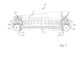
- FIG. 3 shows a strut 1 according to the invention with a roller bearing 11 in a longitudinal section along the central axis 7, wherein the reference numerals to be taken in this embodiment identical to the strut 1 according to the invention FIG. 1 are and are therefore to be taken from this.
Landscapes
- Engineering & Computer Science (AREA)
- Mechanical Engineering (AREA)
- General Engineering & Computer Science (AREA)
- Vehicle Body Suspensions (AREA)
Applications Claiming Priority (1)
| Application Number | Priority Date | Filing Date | Title |
|---|---|---|---|
| DE102010015712A DE102010015712A1 (de) | 2010-04-21 | 2010-04-21 | Federbeinlager und Herstellungsverfahren für ein Bauteil eines Federbeinlagers |
Publications (1)
| Publication Number | Publication Date |
|---|---|
| EP2380762A1 true EP2380762A1 (fr) | 2011-10-26 |
Family
ID=44351814
Family Applications (1)
| Application Number | Title | Priority Date | Filing Date |
|---|---|---|---|
| EP11161093A Withdrawn EP2380762A1 (fr) | 2010-04-21 | 2011-04-05 | Jambe de force de ressort et procédé de fabrication d'un composant d'une jambe de force de ressort |
Country Status (4)
| Country | Link |
|---|---|
| US (1) | US20110262070A1 (fr) |
| EP (1) | EP2380762A1 (fr) |
| KR (1) | KR20110117617A (fr) |
| DE (1) | DE102010015712A1 (fr) |
Cited By (3)
| Publication number | Priority date | Publication date | Assignee | Title |
|---|---|---|---|---|
| CN104936806A (zh) * | 2013-02-07 | 2015-09-23 | 舍弗勒技术股份两合公司 | 悬架支柱轴承 |
| US20150354629A1 (en) * | 2013-01-29 | 2015-12-10 | Oiles Corporation | Synthetic resin-made sliding bearing |
| WO2017041794A1 (fr) * | 2015-09-10 | 2017-03-16 | Schaeffler Technologies AG & Co. KG | Palier de jambe de force |
Families Citing this family (24)
| Publication number | Priority date | Publication date | Assignee | Title |
|---|---|---|---|---|
| JP5332379B2 (ja) * | 2008-07-28 | 2013-11-06 | オイレス工業株式会社 | 合成樹脂製スラスト滑り軸受 |
| US8992094B2 (en) | 2012-07-18 | 2015-03-31 | Schaeffler Technologies AG & Co. KG | Suspension strut bearing |
| DE102012212520B3 (de) | 2012-07-18 | 2013-11-07 | Schaeffler Technologies AG & Co. KG | Federbeinlager |
| DE102012111471B3 (de) * | 2012-11-27 | 2014-05-28 | Thyssen Krupp Bilstein Gmbh | Kopflageranordnung zur Anbindung eines Federbeins an einen Fahrzeugaufbau |
| DE102013208312A1 (de) | 2013-05-07 | 2014-11-13 | Schaeffler Technologies Gmbh & Co. Kg | Federbeinlager |
| DE102014224700B3 (de) * | 2014-12-03 | 2016-03-31 | Schaeffler Technologies AG & Co. KG | Federbeinlager |
| KR101710176B1 (ko) * | 2014-12-31 | 2017-02-27 | 에스케이에프코리아(주) | 이중사출을 이용한 서스펜션 베어링 제조 방법 |
| DE102015217415A1 (de) | 2015-09-11 | 2017-03-16 | Schaeffler Technologies AG & Co. KG | Federbeinlager |
| WO2017041798A1 (fr) | 2015-09-11 | 2017-03-16 | Schaeffler Technologies AG & Co. KG | Appui de jambe de force |
| DE102015217416A1 (de) | 2015-09-11 | 2016-10-13 | Schaeffler Technologies AG & Co. KG | Federbeinlager |
| DE102015221944A1 (de) | 2015-11-09 | 2017-05-11 | Schaeffler Technologies AG & Co. KG | Federbeinlager |
| DE102015119692B4 (de) * | 2015-11-13 | 2025-03-13 | Thyssenkrupp Ag | Aufnahmeanordnung einer Tragfeder für ein Federbein |
| DE102015223279A1 (de) | 2015-11-25 | 2017-06-01 | Schaeffler Technologies AG & Co. KG | Federbeinlager |
| CN109312784B (zh) * | 2016-06-24 | 2020-11-10 | 奥依列斯工业株式会社 | 车辆用推力轴承 |
| DE102016217300B4 (de) | 2016-09-12 | 2018-12-20 | Schaeffler Technologies AG & Co. KG | Federbeinlager |
| DE102018105192A1 (de) | 2018-03-07 | 2019-09-12 | Schaeffler Technologies AG & Co. KG | Verfahren und Computerprogrammprodukt zur Herstellung eines Federbeinlagerbauteils durch einen additiven Fertigungsprozess |
| FR3079169B1 (fr) * | 2018-03-22 | 2021-11-12 | Ntn Snr Roulements | Procede de rigidification d'une coupelle inferieure d'une butee de suspension de vehicule automobile |
| DE102018205359A1 (de) * | 2018-04-10 | 2019-10-10 | Aktiebolaget Skf | Radaufhängungsaxiallagereinheit |
| DE102018217666A1 (de) * | 2018-10-16 | 2020-04-16 | Aktiebolaget Skf | Aufhängungsaxiallagervorrichtung |
| DE102019200695A1 (de) * | 2019-01-21 | 2020-07-23 | Aktiebolaget Skf | Aufhängungsaxiallagervorrichtung und ein mit einer solchen Vorrichtung ausgerüstetes Federbein |
| DE102019110974A1 (de) * | 2019-04-29 | 2020-10-29 | Schaeffler Technologies AG & Co. KG | Federbeinstützlageranordnung für ein Kraftfahrzeug |
| KR102183401B1 (ko) | 2019-07-23 | 2020-11-26 | 조금복 | 용기 위치결정 라벨 부착기 |
| DE202020104632U1 (de) | 2020-08-11 | 2021-11-15 | Rollax Gmbh & Co. Kg | Federbeinlager |
| US20230406087A1 (en) * | 2020-10-14 | 2023-12-21 | Contitech Vibration Control Gmbh | Mount design with integrated tunable retention features |
Citations (11)
| Publication number | Priority date | Publication date | Assignee | Title |
|---|---|---|---|---|
| DE3737770C2 (de) | 1986-12-23 | 1999-06-17 | Oiles Industry Co Ltd | Kunststoff-Drucklager |
| GB2347906A (en) | 1999-03-19 | 2000-09-20 | Draftex Ind Ltd | A suspension strut |
| FR2803561A1 (fr) * | 2000-01-07 | 2001-07-13 | Roulements Soc Nouvelle | Palier de butee de suspension |
| DE10042677A1 (de) | 2000-08-31 | 2002-03-14 | Schaeffler Waelzlager Ohg | Gehäuse für ein Federbeinlager |
| DE202004011432U1 (de) | 2003-07-25 | 2004-09-23 | Aktiebolaget Skf | Federbeinlagerung und Federbein |
| DE102005011408A1 (de) * | 2005-03-11 | 2006-09-14 | Trelleborg Automotive Technical Centre Gmbh | Federauflage für eine Spiralfeder |
| FR2909929A1 (fr) * | 2006-12-18 | 2008-06-20 | Snr Roulements Sa | Dispositif de butee de suspension de vehicule a etancheite renforcee |
| DE102007018160A1 (de) * | 2007-04-18 | 2008-10-23 | Dr. Ing. H.C. F. Porsche Aktiengesellschaft | Lagerteller für eine Schraubenfeder eines Federbeines |
| FR2915929A1 (fr) * | 2007-05-09 | 2008-11-14 | Snr Roulements Sa | Butee de suspension a element filtrant et son procede de fabrication. |
| WO2009106469A1 (fr) * | 2008-02-28 | 2009-09-03 | Aktiebolaget Skf | Dispositif de butée de suspension et jambe de suspension |
| EP2128464A1 (fr) | 2007-03-20 | 2009-12-02 | Oiles Corporation | Palier coulissant à poussée et mécanisme de combinaison du palier coulissant à poussée, tige de piston, et ressort enroulé |
-
2010
- 2010-04-21 DE DE102010015712A patent/DE102010015712A1/de not_active Withdrawn
-
2011
- 2011-04-05 EP EP11161093A patent/EP2380762A1/fr not_active Withdrawn
- 2011-04-20 KR KR1020110036650A patent/KR20110117617A/ko not_active Withdrawn
- 2011-04-21 US US13/091,436 patent/US20110262070A1/en not_active Abandoned
Patent Citations (11)
| Publication number | Priority date | Publication date | Assignee | Title |
|---|---|---|---|---|
| DE3737770C2 (de) | 1986-12-23 | 1999-06-17 | Oiles Industry Co Ltd | Kunststoff-Drucklager |
| GB2347906A (en) | 1999-03-19 | 2000-09-20 | Draftex Ind Ltd | A suspension strut |
| FR2803561A1 (fr) * | 2000-01-07 | 2001-07-13 | Roulements Soc Nouvelle | Palier de butee de suspension |
| DE10042677A1 (de) | 2000-08-31 | 2002-03-14 | Schaeffler Waelzlager Ohg | Gehäuse für ein Federbeinlager |
| DE202004011432U1 (de) | 2003-07-25 | 2004-09-23 | Aktiebolaget Skf | Federbeinlagerung und Federbein |
| DE102005011408A1 (de) * | 2005-03-11 | 2006-09-14 | Trelleborg Automotive Technical Centre Gmbh | Federauflage für eine Spiralfeder |
| FR2909929A1 (fr) * | 2006-12-18 | 2008-06-20 | Snr Roulements Sa | Dispositif de butee de suspension de vehicule a etancheite renforcee |
| EP2128464A1 (fr) | 2007-03-20 | 2009-12-02 | Oiles Corporation | Palier coulissant à poussée et mécanisme de combinaison du palier coulissant à poussée, tige de piston, et ressort enroulé |
| DE102007018160A1 (de) * | 2007-04-18 | 2008-10-23 | Dr. Ing. H.C. F. Porsche Aktiengesellschaft | Lagerteller für eine Schraubenfeder eines Federbeines |
| FR2915929A1 (fr) * | 2007-05-09 | 2008-11-14 | Snr Roulements Sa | Butee de suspension a element filtrant et son procede de fabrication. |
| WO2009106469A1 (fr) * | 2008-02-28 | 2009-09-03 | Aktiebolaget Skf | Dispositif de butée de suspension et jambe de suspension |
Cited By (6)
| Publication number | Priority date | Publication date | Assignee | Title |
|---|---|---|---|---|
| US20150354629A1 (en) * | 2013-01-29 | 2015-12-10 | Oiles Corporation | Synthetic resin-made sliding bearing |
| US9623714B2 (en) * | 2013-01-29 | 2017-04-18 | Oiles Corporation | Synthetic resin-made sliding bearing |
| CN104936806A (zh) * | 2013-02-07 | 2015-09-23 | 舍弗勒技术股份两合公司 | 悬架支柱轴承 |
| US20150367698A1 (en) * | 2013-02-07 | 2015-12-24 | Schaeffler Technologies AG & Co.KG | Strut bearing |
| US9381784B2 (en) * | 2013-02-07 | 2016-07-05 | Schaeffler Technologies AG & Co. KG | Strut bearing |
| WO2017041794A1 (fr) * | 2015-09-10 | 2017-03-16 | Schaeffler Technologies AG & Co. KG | Palier de jambe de force |
Also Published As
| Publication number | Publication date |
|---|---|
| KR20110117617A (ko) | 2011-10-27 |
| US20110262070A1 (en) | 2011-10-27 |
| DE102010015712A1 (de) | 2011-10-27 |
Similar Documents
| Publication | Publication Date | Title |
|---|---|---|
| EP2380762A1 (fr) | Jambe de force de ressort et procédé de fabrication d'un composant d'une jambe de force de ressort | |
| EP2478254B1 (fr) | Manchon élastique, en particulier manchon de bras oscillant combiné | |
| DE102007024628B4 (de) | Radaufhängungseinrichtung und Federbein | |
| EP2619466B1 (fr) | Procédé de fabrication d'un joint à douille à bille | |
| WO2014121772A1 (fr) | Palier de jambe de force | |
| EP2697083B1 (fr) | Palier oscillant | |
| DE102011077336A1 (de) | Radaufhängungselement, umfassend zumindest eine Tragstruktur und einen Lenker | |
| EP3156269A1 (fr) | Manille de fixation d'un ressort a lames sur la carrosserie de véhicules | |
| EP1611367A1 (fr) | Palier a douille en caoutchouc a amortissement hydraulique pour un montage vertical | |
| DE102010025372A1 (de) | Federbeingleitlager | |
| WO2009010053A1 (fr) | Bras de suspension hybride destiné à un véhicule | |
| DE102010024601A1 (de) | Federbeinlager und Herstellungsverfahren für ein reibungsreduzierendes Bauteil eines Federbeinlagers | |
| DE102011015011A1 (de) | Lager, Fahrzeug sowie Verfahren zum Montieren eines Fahrzeugs | |
| DE102016200307A1 (de) | Federteller für einen Schwingungsdämpfer | |
| DE102010035188A1 (de) | Federbeingleitlager | |
| WO2017041798A1 (fr) | Appui de jambe de force | |
| DE102015217289B4 (de) | Federbeinlager | |
| DE102010026854A1 (de) | Federbeingleitlager und Herstellungsverfahren für einen Führungsring eines Federbeingleitlagers | |
| DE102015212640A1 (de) | Federbeinstützlageranordnung für ein Kraftfahrzeug | |
| DE102015217415A1 (de) | Federbeinlager | |
| EP3541643A1 (fr) | Palier d'amortisseur et procédé de fabrication d'un palier d'amortisseur | |
| DE102017213799A1 (de) | Radaufhängung | |
| DE102014225641A1 (de) | Deckel für ein Lenkstangengehäuse | |
| DE102019200995A1 (de) | Anordnung zur Lagerung eines Aggregates in einem Kraftfahrzeug sowie Kraftfahrzeug mit einer derartigen Lagerungsanordnung | |
| DE102016222883A1 (de) | Spritzgussform zur Herstellung einer Kappe eines Federbeinlagers sowie Fe-derbeinlager |
Legal Events
| Date | Code | Title | Description |
|---|---|---|---|
| 17P | Request for examination filed |
Effective date: 20110405 |
|
| AK | Designated contracting states |
Kind code of ref document: A1 Designated state(s): AL AT BE BG CH CY CZ DE DK EE ES FI FR GB GR HR HU IE IS IT LI LT LU LV MC MK MT NL NO PL PT RO RS SE SI SK SM TR |
|
| AX | Request for extension of the european patent |
Extension state: BA ME |
|
| 17Q | First examination report despatched |
Effective date: 20111010 |
|
| PUAI | Public reference made under article 153(3) epc to a published international application that has entered the european phase |
Free format text: ORIGINAL CODE: 0009012 |
|
| RAP1 | Party data changed (applicant data changed or rights of an application transferred) |
Owner name: SCHAEFFLER TECHNOLOGIES AG & CO. KG |
|
| STAA | Information on the status of an ep patent application or granted ep patent |
Free format text: STATUS: THE APPLICATION IS DEEMED TO BE WITHDRAWN |
|
| 18D | Application deemed to be withdrawn |
Effective date: 20120221 |
|
| P01 | Opt-out of the competence of the unified patent court (upc) registered |
Effective date: 20230523 |