EP2381111B1 - Lüfter mit verringertem Lärm - Google Patents
Lüfter mit verringertem Lärm Download PDFInfo
- Publication number
- EP2381111B1 EP2381111B1 EP11275065.8A EP11275065A EP2381111B1 EP 2381111 B1 EP2381111 B1 EP 2381111B1 EP 11275065 A EP11275065 A EP 11275065A EP 2381111 B1 EP2381111 B1 EP 2381111B1
- Authority
- EP
- European Patent Office
- Prior art keywords
- tapered portions
- side section
- suction port
- impeller
- rotational direction
- Prior art date
- Legal status (The legal status is an assumption and is not a legal conclusion. Google has not performed a legal analysis and makes no representation as to the accuracy of the status listed.)
- Active
Links
Images


Classifications
-
- F—MECHANICAL ENGINEERING; LIGHTING; HEATING; WEAPONS; BLASTING
- F04—POSITIVE - DISPLACEMENT MACHINES FOR LIQUIDS; PUMPS FOR LIQUIDS OR ELASTIC FLUIDS
- F04D—NON-POSITIVE-DISPLACEMENT PUMPS
- F04D29/00—Details, component parts, or accessories
- F04D29/40—Casings; Connections of working fluid
- F04D29/52—Casings; Connections of working fluid for axial pumps
-
- F—MECHANICAL ENGINEERING; LIGHTING; HEATING; WEAPONS; BLASTING
- F04—POSITIVE - DISPLACEMENT MACHINES FOR LIQUIDS; PUMPS FOR LIQUIDS OR ELASTIC FLUIDS
- F04D—NON-POSITIVE-DISPLACEMENT PUMPS
- F04D25/00—Pumping installations or systems
- F04D25/02—Units comprising pumps and their driving means
- F04D25/06—Units comprising pumps and their driving means the pump being electrically driven
- F04D25/0606—Units comprising pumps and their driving means the pump being electrically driven the electric motor being specially adapted for integration in the pump
- F04D25/0613—Units comprising pumps and their driving means the pump being electrically driven the electric motor being specially adapted for integration in the pump the electric motor being of the inside-out type, i.e. the rotor is arranged radially outside a central stator
-
- F—MECHANICAL ENGINEERING; LIGHTING; HEATING; WEAPONS; BLASTING
- F04—POSITIVE - DISPLACEMENT MACHINES FOR LIQUIDS; PUMPS FOR LIQUIDS OR ELASTIC FLUIDS
- F04D—NON-POSITIVE-DISPLACEMENT PUMPS
- F04D25/00—Pumping installations or systems
- F04D25/02—Units comprising pumps and their driving means
- F04D25/08—Units comprising pumps and their driving means the working fluid being air, e.g. for ventilation
-
- F—MECHANICAL ENGINEERING; LIGHTING; HEATING; WEAPONS; BLASTING
- F04—POSITIVE - DISPLACEMENT MACHINES FOR LIQUIDS; PUMPS FOR LIQUIDS OR ELASTIC FLUIDS
- F04D—NON-POSITIVE-DISPLACEMENT PUMPS
- F04D29/00—Details, component parts, or accessories
- F04D29/40—Casings; Connections of working fluid
- F04D29/52—Casings; Connections of working fluid for axial pumps
- F04D29/522—Casings; Connections of working fluid for axial pumps especially adapted for elastic fluid pumps
- F04D29/526—Details of the casing section radially opposing blade tips
-
- F—MECHANICAL ENGINEERING; LIGHTING; HEATING; WEAPONS; BLASTING
- F04—POSITIVE - DISPLACEMENT MACHINES FOR LIQUIDS; PUMPS FOR LIQUIDS OR ELASTIC FLUIDS
- F04D—NON-POSITIVE-DISPLACEMENT PUMPS
- F04D29/00—Details, component parts, or accessories
- F04D29/66—Combating cavitation, whirls, noise, vibration or the like; Balancing
- F04D29/661—Combating cavitation, whirls, noise, vibration or the like; Balancing especially adapted for elastic fluid pumps
- F04D29/667—Combating cavitation, whirls, noise, vibration or the like; Balancing especially adapted for elastic fluid pumps by influencing the flow pattern, e.g. suppression of turbulence
-
- F—MECHANICAL ENGINEERING; LIGHTING; HEATING; WEAPONS; BLASTING
- F04—POSITIVE - DISPLACEMENT MACHINES FOR LIQUIDS; PUMPS FOR LIQUIDS OR ELASTIC FLUIDS
- F04D—NON-POSITIVE-DISPLACEMENT PUMPS
- F04D29/00—Details, component parts, or accessories
- F04D29/66—Combating cavitation, whirls, noise, vibration or the like; Balancing
- F04D29/68—Combating cavitation, whirls, noise, vibration or the like; Balancing by influencing boundary layers
- F04D29/681—Combating cavitation, whirls, noise, vibration or the like; Balancing by influencing boundary layers especially adapted for elastic fluid pumps
Definitions
- An object of the present invention is to provide a fan with a noise reduction effect improved over the related art.
- substantially rectangular refers to a perfect rectangular shape with four right-angled corners, a rectangular shape with slightly rounded or tapered corners, a rectangular shape with a groove portion formed at the outer peripheral portion of the rectangular profile to serve as an engagement portion for engagement of a lead wire, and so forth.
- Four tapered portions are formed on an end portion of an inner wall surface of the air channel at four locations corresponding to four corners of the profile of the surface of the housing where the suction port is formed.
- the four tapered portions are each inclined outwardly in a radial direction of the rotary shaft from the discharge port side toward the suction port side, and extend in the rotational direction of the impeller.
- the tapered portions each include a main portion which is shaped such that an angle formed between the main portion and an axis of the rotary shaft becomes gradually smaller from one end of the main portion located rearward as viewed in the rotational direction toward the other end of the main portion located forward as viewed in the rotational direction.
- angle ... becomes gradually smaller refers to a case where the angle becomes smaller stepwise in addition to a case where the angle becomes continuously smaller.
- each of the tapered portions With the main portion of each of the tapered portions at the four corners shaped such that the angle between the main portion and the axis of the rotary shaft becomes gradually smaller from the one end of the main portion located rearward as viewed in the rotational direction toward the other end of the main portion located forward as viewed in the rotational direction as in the present invention, noise produced on the suction port side can be suppressed compared to the related art. This is presumed to be because the shape of each of the tapered portions defined in the present invention reduces the friction resistance between an air flowing into the housing and the edge portion of the suction port to allow the air to be smoothly sucked into the housing.
- each of the tapered portions has a first side section located on the discharge port side and extending in the rotational direction, a second side section located on the suction port side, and a third side section connecting the first side section and the second side section, and is shaped such that the second side section approaches the first side section in the rotational direction.
- a parallel surface extending along the second side section and in parallel with the axis may be formed on a portion of the inner wall surface of the first air channel portion other than the tapered portions.
- another four tapered portions may preferably be formed on an end portion of an inner wall surface of the second air channel portion at four locations corresponding to four corners of the profile of the surface of the housing where the discharge port is formed, and the tapered portions are each inclined outwardly in the radial direction of the rotary shaft from the suction port side toward the discharge port side and extending in the rotational direction of the impeller.
- the four tapered portions provided in the vicinity of the suction port are equal in length in the rotational direction. With this configuration, the air can be sucked into the housing generally uniformly in spite of the presence of the four tapered portions.
- the maximum angle of the main portion of each of the tapered portions with respect to the axis is preferably 5° to 45°.
- the minimum angle of the main portion of each of the tapered portions with respect to the axis is preferably 0°. Such a range of angles is sufficiently effective in reducing noise.
- the main portion of each of the tapered portions may be located between the first side section and the second side section.
- the remaining portion of each of the tapered portions may be located between the first side section and the third side section.
- the length of the remaining portion in the rotational direction may be substantially one fourth of the length of the main portion in the rotational direction or less.
- the plurality of permanent magnets forming the rotor-side magnetic poles 33 are joined on the inner circumferential surface of the peripheral wall portion 31b of the cup-shaped member 31.
- the rotor-side magnetic poles 33 face the magnetic pole surfaces of the stator core 19 of the stator 7.
- the impeller 3 includes an impeller main body 35 and a plurality of (in the embodiment, seven) blades 37 fixed to the impeller main body 35.
- the impeller 3 is integrally formed of a synthetic resin.
- the impeller main body 35 is fixed to the outside of the cup-shaped member 31 of the rotor 11.
- the plurality of blades 37 are shaped to suck an air from the suction port 51 located on one side in the axial direction of the rotary shaft 9 of the motor 1 and to discharge the air from the discharge port 53 located on the other side in the axial direction.
- the housing 5 includes a motor casing 39, a housing main body 41, and four webs 43 that couple the motor casing 39 and the housing main body 41 to each other.
- the housing 5 is integrally formed of a synthetic resin.
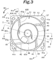
- Figs. 2 and 3 are a perspective view and a plan view, respectively, of the housing 5 as seen from the suction port 51 side.
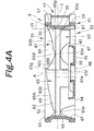
- Figs. 4A to 4D are each a cross-sectional view taken along the line A-A, the line B-B, the line C-C, and the line D-D, respectively, of Fig. 3 .
- a part of the stator 7 and the circuit substrate 27 are housed in the motor casing 39.
- four tapered portions 67 are formed on an end portion of an inner wall surface of the second air channel portion 63 at four locations corresponding to the four corners of the profile of the surface 54 on the discharge port 53 side (the four corner portions of the second flange 59).
- the four tapered portions 67 formed in the second air channel portion 63 are each inclined outwardly in the radial direction of the rotary shaft 9 from the suction port 51 side toward the discharge port 53 side, and extend in the rotational direction of the impeller 3.
- Each of the four tapered portions 65 formed in the first air channel portion 61 is formed in an approximately triangular shape surrounded by first to third side sections 65a to 65c.
- the first side section 65a is located on the discharge port 53 side to extend in the rotational direction (indicated by an arrow RD in Fig. 3 ).
- the first side section 65a has an end portion 65d on a side of the one end, which is located rearward as viewed in the rotational direction RD of the impeller, and an end portion 65e on a side of the other end, which is located forward as viewed in the rotational direction RD of the impeller.
- the end portion 65d on the side of the one end coincides with the end portion 65e of an adjacent tapered portion 65 on the side of the other end.
- the second side section 65b is located on the suction port 51 side.
- the second side section 65b extends in a direction which inclines with respect to the rotational direction RD as parting from the first side section 65a.
- the second side section 65b approaches the first side section (65a) in the rotational direction RD.
- the second side section 65b has an end portion 65f on the side of the one end, which is located rearward as viewed in the rotational direction RD, and the end portion 65e on the side of the other end, at which the second side section 65b is coupled to the first side section 65a.
- the third side section 65c connects the end portion 65d of the first side section 65a on the side of the one end and the end portion 65f of the second side section 65b on the side of the one end.
- a main portion 65A of each of the tapered portions 65 is located between the first side section 65a and the second side section 65b, and shaped such that the second side section 65b approaches the first side section 65a in the rotational direction RD.
- the end portion 65f of the second side section 65b on the side of the one end is continuous with the surface 52 of the housing main body 41 on the suction port 51 side.
- the first side section 65a and the second side section 65b are converged on the side of the other end (the end portion 65e on the side of the other end).
- the remaining portion 65B of the tapered portion 65 is located between the third side section 65c and the first side section 65a.
- a parallel surface 69 extending along the second side section 65b and in parallel with the axis A is formed on a portion of the inner wall surface 62 of the first air channel portion 61 that is adjacent to the tapered portion 65.
- the main portion 65A of each of the tapered portions 65 is outwardly inclined in the radial direction of the rotary shaft 9 from the suction port 53 side toward the discharge port 51 side, and continuously extends in the rotational direction RD of the impeller 3.
- the four tapered portions 65 are equal in length in the rotational direction of the impeller 3 ( Fig. 3 ).
- each of the tapered portions 65 is shaped such that the angle ( ⁇ 1 to ⁇ 4) between the main portion 65A and the axis A of the rotary shaft 9 (or an imaginary line extending in parallel with the axis A) becomes gradually smaller from a one end 65g of the main portion 65A (a position corresponding to the one end 65f of the second side section 65b and indicated by a broken line in Figs.
- the maximum angle of the main portion 65A of the tapered portion 65 with respect to the axis A is 22° ( ⁇ 1 in Fig. 4A ).
- the first side section 65a and the second side section 65b are converged.
- the minimum angle of the tapered portion 65 with respect to the axis A is 0° (see ⁇ 4 in Fig. 4D ) .
- a maximum angle of 5° to 45° is desirable.
- the remaining portion 65B of each of the tapered portions 65 is shaped such that the angle between the remaining portion 65B and the axis A of the rotary shaft 9 (or an imaginary line extending in parallel with the axis A) becomes gradually smaller from the one end 65g described above (a position corresponding to the one end 65f of the second side section 65b) and located forward as viewed in the rotational direction RD of the impeller 3 toward the one end 65d of the first side section 65a located rearward as viewed in the rotational direction RD.
- the length of the remaining portion 65B in the rotational direction RD is substantially one fourth of the length of the main portion 65A in the rotational direction RD or less.
- the variations in angle and the length of the remaining portion 65B according to the embodiment discussed above improve the noise reduction effect of the main portion 65A, rather than reducing it.
- Example the static pressure and air flow characteristics were examined using the fan shown in Figs. 1 to 4 described above (referred to as “Example") and a fan (referred to as “Comparative Example") in which the width (dimension in the axial direction) of the main portion 65A of each of the tapered portions 65 and the angle of the main portion 65A of each of the tapered portions 65 with respect to the axis are constant (with the angle being 22°) and which is otherwise the same in structure as the fan according to Example.
- the fans were rotated at 7000 rpm to measure the relationship of the static pressure with respect to the air flow.
- Fig. 5 shows the measurement results. It was found from Fig. 5 that the fan according to Example and the fan according to Comparative Example had substantially equal static pressure and air flow characteristics.
- Fig. 6 shows the relationship between the frequency components and the sound pressure of noise measured at a position 30 cm away from the center of the suction port of the housing in the axial direction of the rotary shaft.
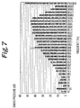
- Fig. 7 shows the relationship between the frequency components and the sound pressure of noise measured at a position 30 cm away from the center of the suction port in a direction orthogonal to the axial direction of the rotary shaft.
- the left bar (in white) indicates data on the fan according to Comparative Example
- the right bar (in black) indicates data on the fan according to Example. It was found from the Figs. 6 and 7 that the sound pressure for the fan according to Example in a relatively high frequency range (2500 to 20000 Hz) was low compared to that for the fan according to Comparative Example. It was also found that the sound pressure for the fan according to Example for frequency components (800 Hz and 1600 Hz) for which the sound pressure of the wind noise is at its peak in Figs.
Landscapes
- Engineering & Computer Science (AREA)
- Mechanical Engineering (AREA)
- General Engineering & Computer Science (AREA)
- Structures Of Non-Positive Displacement Pumps (AREA)
Claims (9)
- Ein Lüfter, aufweisend:einen Impeller (3), umfassend eine Mehrzahl von Flügeln (37);einen Motor (1), umfassend eine Rotationswelle um den Impeller (3) in Rotation zu versetzen; undein Gehäuse (5) mit einer Saugöffnung (51), einer Auslassöffnung (53) und einem Luftkanal (48), in dem zumindest der Impeller (3) angeordnet ist und der es ermöglicht, wenn der Impeller (3) rotoriert, eine Luft von der Saugöffnung (51) anzusaugen und über die Auslassöffnung (53) auszustoßen;wobei eine Oberfläche (52) des Gehäuses (5), durch die die Saugöffnung (51) ausgebildet ist, in ihrem Profil im Wesentlichen rechteckig ist;wobei vier angeschrägte Abschnitte (65) an einem Endabschnitt einer inneren Wandoberfläche des Luftkanals (48) an vier Stellen, die mit vier Ecken des Profils der Oberfläche (52) des Gehäuses (5), an der die Saugöffnung (51) ausgebildet ist, korrespondieren, ausgebildet sind, undjeder der vier aufgeschrägten Abschnitte (65) schräg nach außen in einer radialen Richtung der Rotationswelle (9) von der Seite der Auslassöffnung (53) zu der Seite der Saugöffnung verläuft und sich ein einer Drehrichtung des Impellers (3) erstreckt, dadurch gekennzeichnet, dassjeder der angeschrägten Abschnitte (65) einen Hauptabschnitt (65A) umfasst, der derart geformt ist, dass ein zwischen dem Hauptabschnitt (65A) und einer Achse (A) der Rotationswelle (9) ausgebildeter Winkel (01-04) von einem Ende (65g) des Hauptabschnitts (65A), das, betrachtet in der Drehrichtung des Impellers (3), hinten angeordnet ist, zu dem anderen Ende (65e) des Hauptabschnitts (65A), das, betrachtet in der Drehrichtung des Impellers (3), vorne angeordnet ist, graduell kleiner wird.
- Der Lüfter nach Anspruch 1, wobei,
angenommen, dass der Luftkanal (48) durch eine imaginäre Ebene, die senkrecht auf der Achse (A) steht, in einen ersten Luftkanalabschnitt (61), der an der Seite der Saugöffnung (51) angeordnet ist, und einen zweiten Luftkanalabschnitt (63), der an der Seite der Auslassöffnung (53) angeordnet ist, halbiert ist, die angeschrägten Abschnitte (65) an einer inneren Wandoberfläche des ersten Luftkanalabschnitts (61) ausgebildet sind. - Der Lüfter nach Anspruch 2, wobei
der Hauptabschnitt (65A) jedes der angeschrägten Abschnitte (65) einen ersten seitlichen Abschnitt (65a), der an der Seite der Auslassöffnung angeordnet ist und sich in Drehrichtung erstreckt, einen zweiten seitlichen Abschnitt (65b), der an der Seite der Saugöffnung angeordnet ist, und einen dritten Seitenabschnitt (65c), der den ersten seitlichen und den zweiten seitlichen Abschnitt (65a), (65b) verbindet, aufweist,
und der Hauptabschnitt (65A) jedes der angeschrägten Abschnitte (61) derart geformt ist, dass sich der zweite seitliche Abschnitt (65b) dem ersten seitlichen Abschnitt (65a) in der Drehrichtung annähert. - Der Lüfter nach Anspruch 3, wobei
ein Endabschnitt (65f) des zweiten seitlichen Abschnitts (65b) jedes der angeschrägten Abschnitte (61), der an einer Seite des einen Endes (65g) ist, kontinuierlich mit der Oberfläche (52) des Gehäuses (5), in der die Saugöffnung (51) ausgebildet ist, ist; und
der erste seitliche Abschnitt (65a) und der zweite seitliche Abschnitt (65b) an einer Seite des anderen Endes (65e) zusammenlaufen. - Der Lüfter nach Anspruch 4, wobei
eine parallele Oberfläche (69), die sich entlang des zweiten seitlichen Abschnitts (65b) und parallel zur Achse (A) erstreckt, an der inneren Wandoberfläche (62) des ersten Luftkanalabschnitts (61) ausgebildet ist. - Der Lüfter nach Anspruch 1, wobei
die vier angeschrägten Abschnitte (65), bezüglich der Drehrichtung, eine gleiche Länge aufweisen. - Der Lüfter nach Anspruch 2, wobei
der maximale Winkel des Hauptabschnitts (65A) jedes der angeschrägten Abschnitte (65) bezüglich der Achse (A) zwischen 5 und 45° ist, und der minimale Winkel des Hauptabschnitts (65A) jedes der angeschrägten Abschnitte (65) bezüglich der Achse (A) 0° ist. - Der Lüfter nach Anspruch 1, wobei:der Hauptabschnitt (65A) jedes der angeschrägten Abschnitte (65) zwischen dem ersten seitlichen Abschnitt (65a) und dem zweiten seitlichen Abschnitt (65b) angeordnet ist;ein verbleibender Abschnitt (65B) jedes der angeschrägten Abschnitte (65) zwischen dem ersten seitlichen Abschnitt (65a) und dem dritten seitlichen Abschnitt (65c) angeordnet ist; unddie Länge des verbleibenden Abschnitts (65B) in der Drehrichtung im Wesentlichen ein Viertel der Länge des Hauptabschnitts (65A) in Drehrichtung oder weniger ist.
- Der Lüfter nach einem der Ansprüche 2 bis 8, wobei
eine Oberfläche (54) des Gehäuses (5), in der die Auslassöffnung (53) ausgebildet ist, in ihrem Profil im Wesentlichen rechteckig ist; und
vier angeschrägte Abschnitte (67) an einem Endabschnitt einer inneren Wandoberfläche des zweiten Luftkanalabschnitts (63) an vier Stellen, die mit vier Ecken des Profils jener Oberfläche (54) des Gehäuses (5), an der die Auslassöffnung (53) ausgebildet ist, korrespondieren, ausgebildet sind, und
jeder der vier angeschrägten Abschnitte schräg nach außen in einer radialen Richtung der Rotationswelle (9) von der Seite der Saugöffnung (51) zu der Seite der Auslassöffnung (53) verläuft und sich ein einer Drehrichtung des Impellers (3) erstreckt.
Applications Claiming Priority (2)
| Application Number | Priority Date | Filing Date | Title |
|---|---|---|---|
| JP2010097131 | 2010-04-20 | ||
| JP2011064585A JP5739200B2 (ja) | 2010-04-20 | 2011-03-23 | 送風機 |
Publications (3)
| Publication Number | Publication Date |
|---|---|
| EP2381111A2 EP2381111A2 (de) | 2011-10-26 |
| EP2381111A3 EP2381111A3 (de) | 2018-03-07 |
| EP2381111B1 true EP2381111B1 (de) | 2019-07-10 |
Family
ID=44343970
Family Applications (1)
| Application Number | Title | Priority Date | Filing Date |
|---|---|---|---|
| EP11275065.8A Active EP2381111B1 (de) | 2010-04-20 | 2011-04-20 | Lüfter mit verringertem Lärm |
Country Status (7)
| Country | Link |
|---|---|
| US (1) | US8651807B2 (de) |
| EP (1) | EP2381111B1 (de) |
| JP (1) | JP5739200B2 (de) |
| KR (1) | KR20110117006A (de) |
| CN (1) | CN102235389B (de) |
| PH (1) | PH12011000128A1 (de) |
| TW (1) | TW201207247A (de) |
Families Citing this family (16)
| Publication number | Priority date | Publication date | Assignee | Title |
|---|---|---|---|---|
| US8814501B2 (en) * | 2010-08-06 | 2014-08-26 | Minebea Co., Ltd. (Minebea) | Fan with area expansion between rotor and stator blades |
| JP5834342B2 (ja) * | 2011-12-12 | 2015-12-16 | 日本電産株式会社 | ファン |
| JP6062658B2 (ja) * | 2012-05-11 | 2017-01-18 | 山洋電気株式会社 | ファンフレーム |
| JP5992778B2 (ja) * | 2012-09-06 | 2016-09-14 | 山洋電気株式会社 | 軸流ファン |
| TWI546455B (zh) * | 2012-12-13 | 2016-08-21 | 鴻準精密工業股份有限公司 | 磁框、轉子及風扇 |
| JP5705945B1 (ja) * | 2013-10-28 | 2015-04-22 | ミネベア株式会社 | 遠心式ファン |
| JP6385752B2 (ja) * | 2013-12-02 | 2018-09-05 | 三星電子株式会社Samsung Electronics Co.,Ltd. | 送風装置及び空気調和装置用室外機 |
| US9651054B2 (en) * | 2014-02-11 | 2017-05-16 | Asia Vital Components Co., Ltd. | Series fan frame body structure made of different materials |
| US9945390B2 (en) * | 2014-07-31 | 2018-04-17 | Regal Beloit America, Inc. | Centrifugal blower and method of assembling the same |
| CN107575408A (zh) * | 2015-03-02 | 2018-01-12 | 联想(北京)有限公司 | 风扇和具有风扇的电子产品 |
| JP5832052B1 (ja) * | 2015-04-24 | 2015-12-16 | 山洋電気株式会社 | 双方向軸流ファン装置 |
| TWI758601B (zh) * | 2018-05-04 | 2022-03-21 | 奇鋐科技股份有限公司 | 風扇降噪結構 |
| TWI671470B (zh) * | 2018-05-04 | 2019-09-11 | 奇鋐科技股份有限公司 | 風扇降噪結構 |
| US11326624B2 (en) | 2018-05-15 | 2022-05-10 | Asia Vital Components Co., Ltd. | Fan noise-lowering structure |
| US11326623B2 (en) | 2018-05-15 | 2022-05-10 | Asia Vital Components Co., Ltd. | Fan noise-lowering structure |
| US11255339B2 (en) * | 2018-08-28 | 2022-02-22 | Honeywell International Inc. | Fan structure having integrated rotor impeller, and methods of producing the same |
Family Cites Families (18)
| Publication number | Priority date | Publication date | Assignee | Title |
|---|---|---|---|---|
| DE10020878C2 (de) * | 2000-04-28 | 2002-05-02 | Verax Ventilatoren Gmbh | Lüfter insbesondere zur Belüftung von elektronischen Geräten |
| TW566073B (en) * | 2003-04-11 | 2003-12-11 | Delta Electronics Inc | Heat-dissipating device and a housing thereof |
| CN100353077C (zh) * | 2004-05-25 | 2007-12-05 | 建准电机工业股份有限公司 | 轴流风扇的出风构造 |
| TWI288210B (en) * | 2004-08-18 | 2007-10-11 | Delta Electronics Inc | Heat-dissipating fan and its housing |
| TWI305486B (en) * | 2004-08-27 | 2009-01-11 | Delta Electronics Inc | Heat-dissipating fan and its housing |
| TWI305612B (en) * | 2004-08-27 | 2009-01-21 | Delta Electronics Inc | Heat-dissipating fan |
| US20060067816A1 (en) * | 2004-09-24 | 2006-03-30 | Bor-Haw Chang | Cooling fan with fluid control device |
| JP2007198327A (ja) * | 2006-01-30 | 2007-08-09 | Seiko Epson Corp | 送風機 |
| JP2007218101A (ja) * | 2006-02-14 | 2007-08-30 | Nippon Densan Corp | 軸流ファンのハウジングおよび軸流ファン |
| JP2008014302A (ja) * | 2006-06-09 | 2008-01-24 | Nippon Densan Corp | 軸流ファン |
| JP2008175142A (ja) * | 2007-01-18 | 2008-07-31 | Nippon Densan Corp | ファン装置 |
| JP2008261280A (ja) * | 2007-04-12 | 2008-10-30 | Nippon Densan Corp | 軸流ファン |
| CN101307769B (zh) * | 2007-05-16 | 2013-04-03 | 台达电子工业股份有限公司 | 风扇及风扇组件 |
| CN101319686B (zh) * | 2007-06-05 | 2011-11-23 | 台达电子工业股份有限公司 | 风扇及其扇框 |
| JP2009019511A (ja) * | 2007-07-10 | 2009-01-29 | Nippon Densan Corp | 直列式軸流ファン |
| JP2009108792A (ja) * | 2007-10-31 | 2009-05-21 | Nippon Densan Corp | ファン装置 |
| TW200939939A (en) * | 2008-03-07 | 2009-09-16 | Delta Electronics Inc | Fan and fan frame thereof |
| JP5129667B2 (ja) * | 2008-06-26 | 2013-01-30 | 山洋電気株式会社 | 軸流送風機 |
-
2011
- 2011-03-23 JP JP2011064585A patent/JP5739200B2/ja active Active
- 2011-04-19 US US13/089,567 patent/US8651807B2/en active Active
- 2011-04-19 TW TW100113552A patent/TW201207247A/zh unknown
- 2011-04-19 CN CN201110102540.7A patent/CN102235389B/zh active Active
- 2011-04-19 KR KR1020110036026A patent/KR20110117006A/ko not_active Withdrawn
- 2011-04-19 PH PH1/2011/000128A patent/PH12011000128A1/en unknown
- 2011-04-20 EP EP11275065.8A patent/EP2381111B1/de active Active
Non-Patent Citations (1)
| Title |
|---|
| None * |
Also Published As
| Publication number | Publication date |
|---|---|
| US20110255957A1 (en) | 2011-10-20 |
| US8651807B2 (en) | 2014-02-18 |
| JP5739200B2 (ja) | 2015-06-24 |
| CN102235389B (zh) | 2014-11-05 |
| JP2011241815A (ja) | 2011-12-01 |
| TW201207247A (en) | 2012-02-16 |
| EP2381111A3 (de) | 2018-03-07 |
| KR20110117006A (ko) | 2011-10-26 |
| PH12011000128A1 (en) | 2013-05-06 |
| EP2381111A2 (de) | 2011-10-26 |
| CN102235389A (zh) | 2011-11-09 |
Similar Documents
| Publication | Publication Date | Title |
|---|---|---|
| EP2381111B1 (de) | Lüfter mit verringertem Lärm | |
| US6551074B2 (en) | Centrifugal fan with waterproof structure | |
| US8961121B2 (en) | Centrifugal fan | |
| TWI381097B (zh) | 雙重反轉式軸流送風機 | |
| JP6126984B2 (ja) | 防水型軸流ファン | |
| EP2261511B1 (de) | Zentrifugalgebläse | |
| US11286953B2 (en) | Blower | |
| TWI516684B (zh) | 離心式風扇 | |
| US20110194955A1 (en) | Electric fan | |
| US20070140844A1 (en) | Axial Flow Fan | |
| US8764418B2 (en) | Centrifugal fan | |
| JP6012034B2 (ja) | 軸流ファン | |
| JP2008017607A (ja) | ブラシレスファンモータ | |
| CN111379715A (zh) | 送风装置 | |
| JP2016208790A (ja) | モータおよび遠心送風機 | |
| TWI589782B (zh) | 軸流風扇 | |
| US7866945B2 (en) | Axial flow fan | |
| JP2007192217A (ja) | 軸流ファン | |
| WO2020209196A1 (ja) | 軸流ファンのファンフレーム構造 | |
| WO2006082877A1 (ja) | 軸流送風機 | |
| KR102684391B1 (ko) | 팬-모터 조립체 |
Legal Events
| Date | Code | Title | Description |
|---|---|---|---|
| AK | Designated contracting states |
Kind code of ref document: A2 Designated state(s): AL AT BE BG CH CY CZ DE DK EE ES FI FR GB GR HR HU IE IS IT LI LT LU LV MC MK MT NL NO PL PT RO RS SE SI SK SM TR |
|
| AX | Request for extension of the european patent |
Extension state: BA ME |
|
| PUAI | Public reference made under article 153(3) epc to a published international application that has entered the european phase |
Free format text: ORIGINAL CODE: 0009012 |
|
| PUAL | Search report despatched |
Free format text: ORIGINAL CODE: 0009013 |
|
| AK | Designated contracting states |
Kind code of ref document: A3 Designated state(s): AL AT BE BG CH CY CZ DE DK EE ES FI FR GB GR HR HU IE IS IT LI LT LU LV MC MK MT NL NO PL PT RO RS SE SI SK SM TR |
|
| AX | Request for extension of the european patent |
Extension state: BA ME |
|
| RIC1 | Information provided on ipc code assigned before grant |
Ipc: F04D 29/52 20060101ALI20180201BHEP Ipc: F04D 29/66 20060101ALI20180201BHEP Ipc: F04D 29/68 20060101ALI20180201BHEP Ipc: F04D 25/06 20060101AFI20180201BHEP |
|
| STAA | Information on the status of an ep patent application or granted ep patent |
Free format text: STATUS: REQUEST FOR EXAMINATION WAS MADE |
|
| 17P | Request for examination filed |
Effective date: 20180906 |
|
| RBV | Designated contracting states (corrected) |
Designated state(s): AL AT BE BG CH CY CZ DE DK EE ES FI FR GB GR HR HU IE IS IT LI LT LU LV MC MK MT NL NO PL PT RO RS SE SI SK SM TR |
|
| GRAP | Despatch of communication of intention to grant a patent |
Free format text: ORIGINAL CODE: EPIDOSNIGR1 |
|
| STAA | Information on the status of an ep patent application or granted ep patent |
Free format text: STATUS: GRANT OF PATENT IS INTENDED |
|
| INTG | Intention to grant announced |
Effective date: 20190123 |
|
| GRAS | Grant fee paid |
Free format text: ORIGINAL CODE: EPIDOSNIGR3 |
|
| GRAA | (expected) grant |
Free format text: ORIGINAL CODE: 0009210 |
|
| STAA | Information on the status of an ep patent application or granted ep patent |
Free format text: STATUS: THE PATENT HAS BEEN GRANTED |
|
| AK | Designated contracting states |
Kind code of ref document: B1 Designated state(s): AL AT BE BG CH CY CZ DE DK EE ES FI FR GB GR HR HU IE IS IT LI LT LU LV MC MK MT NL NO PL PT RO RS SE SI SK SM TR |
|
| REG | Reference to a national code |
Ref country code: GB Ref legal event code: FG4D |
|
| REG | Reference to a national code |
Ref country code: CH Ref legal event code: EP Ref country code: AT Ref legal event code: REF Ref document number: 1153858 Country of ref document: AT Kind code of ref document: T Effective date: 20190715 |
|
| REG | Reference to a national code |
Ref country code: DE Ref legal event code: R096 Ref document number: 602011060319 Country of ref document: DE |
|
| REG | Reference to a national code |
Ref country code: IE Ref legal event code: FG4D |
|
| REG | Reference to a national code |
Ref country code: NL Ref legal event code: MP Effective date: 20190710 |
|
| REG | Reference to a national code |
Ref country code: LT Ref legal event code: MG4D |
|
| REG | Reference to a national code |
Ref country code: AT Ref legal event code: MK05 Ref document number: 1153858 Country of ref document: AT Kind code of ref document: T Effective date: 20190710 |
|
| PG25 | Lapsed in a contracting state [announced via postgrant information from national office to epo] |
Ref country code: FI Free format text: LAPSE BECAUSE OF FAILURE TO SUBMIT A TRANSLATION OF THE DESCRIPTION OR TO PAY THE FEE WITHIN THE PRESCRIBED TIME-LIMIT Effective date: 20190710 Ref country code: SE Free format text: LAPSE BECAUSE OF FAILURE TO SUBMIT A TRANSLATION OF THE DESCRIPTION OR TO PAY THE FEE WITHIN THE PRESCRIBED TIME-LIMIT Effective date: 20190710 Ref country code: NO Free format text: LAPSE BECAUSE OF FAILURE TO SUBMIT A TRANSLATION OF THE DESCRIPTION OR TO PAY THE FEE WITHIN THE PRESCRIBED TIME-LIMIT Effective date: 20191010 Ref country code: AT Free format text: LAPSE BECAUSE OF FAILURE TO SUBMIT A TRANSLATION OF THE DESCRIPTION OR TO PAY THE FEE WITHIN THE PRESCRIBED TIME-LIMIT Effective date: 20190710 Ref country code: HR Free format text: LAPSE BECAUSE OF FAILURE TO SUBMIT A TRANSLATION OF THE DESCRIPTION OR TO PAY THE FEE WITHIN THE PRESCRIBED TIME-LIMIT Effective date: 20190710 Ref country code: LT Free format text: LAPSE BECAUSE OF FAILURE TO SUBMIT A TRANSLATION OF THE DESCRIPTION OR TO PAY THE FEE WITHIN THE PRESCRIBED TIME-LIMIT Effective date: 20190710 Ref country code: NL Free format text: LAPSE BECAUSE OF FAILURE TO SUBMIT A TRANSLATION OF THE DESCRIPTION OR TO PAY THE FEE WITHIN THE PRESCRIBED TIME-LIMIT Effective date: 20190710 Ref country code: PT Free format text: LAPSE BECAUSE OF FAILURE TO SUBMIT A TRANSLATION OF THE DESCRIPTION OR TO PAY THE FEE WITHIN THE PRESCRIBED TIME-LIMIT Effective date: 20191111 Ref country code: BG Free format text: LAPSE BECAUSE OF FAILURE TO SUBMIT A TRANSLATION OF THE DESCRIPTION OR TO PAY THE FEE WITHIN THE PRESCRIBED TIME-LIMIT Effective date: 20191010 |
|
| PG25 | Lapsed in a contracting state [announced via postgrant information from national office to epo] |
Ref country code: LV Free format text: LAPSE BECAUSE OF FAILURE TO SUBMIT A TRANSLATION OF THE DESCRIPTION OR TO PAY THE FEE WITHIN THE PRESCRIBED TIME-LIMIT Effective date: 20190710 Ref country code: GR Free format text: LAPSE BECAUSE OF FAILURE TO SUBMIT A TRANSLATION OF THE DESCRIPTION OR TO PAY THE FEE WITHIN THE PRESCRIBED TIME-LIMIT Effective date: 20191011 Ref country code: AL Free format text: LAPSE BECAUSE OF FAILURE TO SUBMIT A TRANSLATION OF THE DESCRIPTION OR TO PAY THE FEE WITHIN THE PRESCRIBED TIME-LIMIT Effective date: 20190710 Ref country code: ES Free format text: LAPSE BECAUSE OF FAILURE TO SUBMIT A TRANSLATION OF THE DESCRIPTION OR TO PAY THE FEE WITHIN THE PRESCRIBED TIME-LIMIT Effective date: 20190710 Ref country code: IS Free format text: LAPSE BECAUSE OF FAILURE TO SUBMIT A TRANSLATION OF THE DESCRIPTION OR TO PAY THE FEE WITHIN THE PRESCRIBED TIME-LIMIT Effective date: 20191110 Ref country code: RS Free format text: LAPSE BECAUSE OF FAILURE TO SUBMIT A TRANSLATION OF THE DESCRIPTION OR TO PAY THE FEE WITHIN THE PRESCRIBED TIME-LIMIT Effective date: 20190710 |
|
| PG25 | Lapsed in a contracting state [announced via postgrant information from national office to epo] |
Ref country code: TR Free format text: LAPSE BECAUSE OF FAILURE TO SUBMIT A TRANSLATION OF THE DESCRIPTION OR TO PAY THE FEE WITHIN THE PRESCRIBED TIME-LIMIT Effective date: 20190710 |
|
| PG25 | Lapsed in a contracting state [announced via postgrant information from national office to epo] |
Ref country code: EE Free format text: LAPSE BECAUSE OF FAILURE TO SUBMIT A TRANSLATION OF THE DESCRIPTION OR TO PAY THE FEE WITHIN THE PRESCRIBED TIME-LIMIT Effective date: 20190710 Ref country code: RO Free format text: LAPSE BECAUSE OF FAILURE TO SUBMIT A TRANSLATION OF THE DESCRIPTION OR TO PAY THE FEE WITHIN THE PRESCRIBED TIME-LIMIT Effective date: 20190710 Ref country code: PL Free format text: LAPSE BECAUSE OF FAILURE TO SUBMIT A TRANSLATION OF THE DESCRIPTION OR TO PAY THE FEE WITHIN THE PRESCRIBED TIME-LIMIT Effective date: 20190710 Ref country code: IT Free format text: LAPSE BECAUSE OF FAILURE TO SUBMIT A TRANSLATION OF THE DESCRIPTION OR TO PAY THE FEE WITHIN THE PRESCRIBED TIME-LIMIT Effective date: 20190710 Ref country code: DK Free format text: LAPSE BECAUSE OF FAILURE TO SUBMIT A TRANSLATION OF THE DESCRIPTION OR TO PAY THE FEE WITHIN THE PRESCRIBED TIME-LIMIT Effective date: 20190710 |
|
| PG25 | Lapsed in a contracting state [announced via postgrant information from national office to epo] |
Ref country code: SK Free format text: LAPSE BECAUSE OF FAILURE TO SUBMIT A TRANSLATION OF THE DESCRIPTION OR TO PAY THE FEE WITHIN THE PRESCRIBED TIME-LIMIT Effective date: 20190710 Ref country code: CZ Free format text: LAPSE BECAUSE OF FAILURE TO SUBMIT A TRANSLATION OF THE DESCRIPTION OR TO PAY THE FEE WITHIN THE PRESCRIBED TIME-LIMIT Effective date: 20190710 Ref country code: SM Free format text: LAPSE BECAUSE OF FAILURE TO SUBMIT A TRANSLATION OF THE DESCRIPTION OR TO PAY THE FEE WITHIN THE PRESCRIBED TIME-LIMIT Effective date: 20190710 Ref country code: IS Free format text: LAPSE BECAUSE OF FAILURE TO SUBMIT A TRANSLATION OF THE DESCRIPTION OR TO PAY THE FEE WITHIN THE PRESCRIBED TIME-LIMIT Effective date: 20200224 |
|
| REG | Reference to a national code |
Ref country code: DE Ref legal event code: R097 Ref document number: 602011060319 Country of ref document: DE |
|
| PLBE | No opposition filed within time limit |
Free format text: ORIGINAL CODE: 0009261 |
|
| STAA | Information on the status of an ep patent application or granted ep patent |
Free format text: STATUS: NO OPPOSITION FILED WITHIN TIME LIMIT |
|
| PG2D | Information on lapse in contracting state deleted |
Ref country code: IS |
|
| 26N | No opposition filed |
Effective date: 20200603 |
|
| PG25 | Lapsed in a contracting state [announced via postgrant information from national office to epo] |
Ref country code: SI Free format text: LAPSE BECAUSE OF FAILURE TO SUBMIT A TRANSLATION OF THE DESCRIPTION OR TO PAY THE FEE WITHIN THE PRESCRIBED TIME-LIMIT Effective date: 20190710 |
|
| PG25 | Lapsed in a contracting state [announced via postgrant information from national office to epo] |
Ref country code: MC Free format text: LAPSE BECAUSE OF FAILURE TO SUBMIT A TRANSLATION OF THE DESCRIPTION OR TO PAY THE FEE WITHIN THE PRESCRIBED TIME-LIMIT Effective date: 20190710 |
|
| REG | Reference to a national code |
Ref country code: CH Ref legal event code: PL |
|
| PG25 | Lapsed in a contracting state [announced via postgrant information from national office to epo] |
Ref country code: LI Free format text: LAPSE BECAUSE OF NON-PAYMENT OF DUE FEES Effective date: 20200430 Ref country code: LU Free format text: LAPSE BECAUSE OF NON-PAYMENT OF DUE FEES Effective date: 20200420 Ref country code: CH Free format text: LAPSE BECAUSE OF NON-PAYMENT OF DUE FEES Effective date: 20200430 |
|
| REG | Reference to a national code |
Ref country code: BE Ref legal event code: MM Effective date: 20200430 |
|
| PG25 | Lapsed in a contracting state [announced via postgrant information from national office to epo] |
Ref country code: BE Free format text: LAPSE BECAUSE OF NON-PAYMENT OF DUE FEES Effective date: 20200430 |
|
| PG25 | Lapsed in a contracting state [announced via postgrant information from national office to epo] |
Ref country code: IE Free format text: LAPSE BECAUSE OF NON-PAYMENT OF DUE FEES Effective date: 20200420 |
|
| PG25 | Lapsed in a contracting state [announced via postgrant information from national office to epo] |
Ref country code: MT Free format text: LAPSE BECAUSE OF FAILURE TO SUBMIT A TRANSLATION OF THE DESCRIPTION OR TO PAY THE FEE WITHIN THE PRESCRIBED TIME-LIMIT Effective date: 20190710 Ref country code: CY Free format text: LAPSE BECAUSE OF FAILURE TO SUBMIT A TRANSLATION OF THE DESCRIPTION OR TO PAY THE FEE WITHIN THE PRESCRIBED TIME-LIMIT Effective date: 20190710 |
|
| PG25 | Lapsed in a contracting state [announced via postgrant information from national office to epo] |
Ref country code: MK Free format text: LAPSE BECAUSE OF FAILURE TO SUBMIT A TRANSLATION OF THE DESCRIPTION OR TO PAY THE FEE WITHIN THE PRESCRIBED TIME-LIMIT Effective date: 20190710 |
|
| PGFP | Annual fee paid to national office [announced via postgrant information from national office to epo] |
Ref country code: DE Payment date: 20250422 Year of fee payment: 15 |
|
| PGFP | Annual fee paid to national office [announced via postgrant information from national office to epo] |
Ref country code: GB Payment date: 20250423 Year of fee payment: 15 |
|
| PGFP | Annual fee paid to national office [announced via postgrant information from national office to epo] |
Ref country code: FR Payment date: 20250424 Year of fee payment: 15 |