EP2381140B1 - Procédé de commande de changement de vitesse d'une boîte de vitesse automatisée - Google Patents
Procédé de commande de changement de vitesse d'une boîte de vitesse automatisée Download PDFInfo
- Publication number
- EP2381140B1 EP2381140B1 EP20110156606 EP11156606A EP2381140B1 EP 2381140 B1 EP2381140 B1 EP 2381140B1 EP 20110156606 EP20110156606 EP 20110156606 EP 11156606 A EP11156606 A EP 11156606A EP 2381140 B1 EP2381140 B1 EP 2381140B1
- Authority
- EP
- European Patent Office
- Prior art keywords
- torque
- engine
- turbine
- clutch
- load
- Prior art date
- Legal status (The legal status is an assumption and is not a legal conclusion. Google has not performed a legal analysis and makes no representation as to the accuracy of the status listed.)
- Not-in-force
Links
Images

Classifications
-
- F—MECHANICAL ENGINEERING; LIGHTING; HEATING; WEAPONS; BLASTING
- F16—ENGINEERING ELEMENTS AND UNITS; GENERAL MEASURES FOR PRODUCING AND MAINTAINING EFFECTIVE FUNCTIONING OF MACHINES OR INSTALLATIONS; THERMAL INSULATION IN GENERAL
- F16H—GEARING
- F16H61/00—Control functions within control units of change-speed- or reversing-gearings for conveying rotary motion ; Control of exclusively fluid gearing, friction gearing, gearings with endless flexible members or other particular types of gearing
- F16H61/04—Smoothing ratio shift
- F16H61/0437—Smoothing ratio shift by using electrical signals
-
- F—MECHANICAL ENGINEERING; LIGHTING; HEATING; WEAPONS; BLASTING
- F16—ENGINEERING ELEMENTS AND UNITS; GENERAL MEASURES FOR PRODUCING AND MAINTAINING EFFECTIVE FUNCTIONING OF MACHINES OR INSTALLATIONS; THERMAL INSULATION IN GENERAL
- F16H—GEARING
- F16H61/00—Control functions within control units of change-speed- or reversing-gearings for conveying rotary motion ; Control of exclusively fluid gearing, friction gearing, gearings with endless flexible members or other particular types of gearing
- F16H61/14—Control of torque converter lock-up clutches
- F16H61/143—Control of torque converter lock-up clutches using electric control means
-
- F—MECHANICAL ENGINEERING; LIGHTING; HEATING; WEAPONS; BLASTING
- F16—ENGINEERING ELEMENTS AND UNITS; GENERAL MEASURES FOR PRODUCING AND MAINTAINING EFFECTIVE FUNCTIONING OF MACHINES OR INSTALLATIONS; THERMAL INSULATION IN GENERAL
- F16H—GEARING
- F16H63/00—Control outputs from the control unit to change-speed- or reversing-gearings for conveying rotary motion or to other devices than the final output mechanism
- F16H63/40—Control outputs from the control unit to change-speed- or reversing-gearings for conveying rotary motion or to other devices than the final output mechanism comprising signals other than signals for actuating the final output mechanisms
- F16H63/50—Signals to an engine or motor
- F16H2063/506—Signals to an engine or motor for engine torque resume after shift transition, e.g. a resume adapted to the driving style
-
- F—MECHANICAL ENGINEERING; LIGHTING; HEATING; WEAPONS; BLASTING
- F16—ENGINEERING ELEMENTS AND UNITS; GENERAL MEASURES FOR PRODUCING AND MAINTAINING EFFECTIVE FUNCTIONING OF MACHINES OR INSTALLATIONS; THERMAL INSULATION IN GENERAL
- F16H—GEARING
- F16H2306/00—Shifting
- F16H2306/40—Shifting activities
- F16H2306/52—Applying torque to new gears
-
- F—MECHANICAL ENGINEERING; LIGHTING; HEATING; WEAPONS; BLASTING
- F16—ENGINEERING ELEMENTS AND UNITS; GENERAL MEASURES FOR PRODUCING AND MAINTAINING EFFECTIVE FUNCTIONING OF MACHINES OR INSTALLATIONS; THERMAL INSULATION IN GENERAL
- F16H—GEARING
- F16H45/00—Combinations of fluid gearings for conveying rotary motion with couplings or clutches
- F16H45/02—Combinations of fluid gearings for conveying rotary motion with couplings or clutches with mechanical clutches for bridging a fluid gearing of the hydrokinetic type
Definitions
- the invention relates to a method for switching control of an automated manual transmission according to the preamble of patent claim 1, as described in the DE 100 45 337A1 ,
- a transmission type known per se in which circuits, in contrast to so-called powershift transmissions, such as planetary automatic transmissions and dual-clutch transmissions, are connected to a pull or thrust interruption.
- Such transmissions are mostly of the countershaft type and have a single input shaft which is usually connected via an automated friction clutch, such as an automatic transmission clutch.
- an automated friction clutch such as an automatic transmission clutch.
- a passively closable single or multi-disc dry clutch or an actively closable multi-plate clutch with the drive shaft of the drive motor can be connected or separated from this.
- Such a friction clutch serves both as a starting element and as a clutch.
- the friction clutch bridges during startup operations in the slip operation, the speed difference between the drive shaft of the drive motor and the input shaft of the gearbox. The same applies to maneuvering, crawling and driving at low speed, if there is no correspondingly high translated creeper available.
- the friction clutch at the beginning of a Switching fully open to allow the load-free interpretation of the loaded load gear and the load-free synchronization and insertion of the target gear, and subsequently completely closed again.
- the publications DE 10 2004 059 733 A1 and DE 10 2004 059 744 A1 disclose a gear unit with a starting element in the form of a hydrodynamic component, with a device associated with the starting element for bridging the starting element and with a change gear comprising at least one gear ratio forming speed / torque converter.
- the bypass device comprises a bypass circuit for selectively transmitting power via two power branches - a first hydrodynamic power branch and a second mechanical power branch between the transmission input and the input of the gearbox.
- the lockup circuit includes two speed / torque converters.
- At least one of the speed / torque conversion means of the lock-up circuit and / or at least one element of the speed-forming Drehiere- / Drehmomentwandlungseiniichtitch in different power transmission branches between the transmission input and transmission output can be integrated or switched.
- the transmission unit according to the DE 10 2004 059 744 A1 discloses means for selectively interrupting or ensuring power transmission across the individual power branches.
- the means comprise for selectively interrupting or guaranteeing the power transmission across the individual power branches a arranged in the hydrodynamic power branch between the secondary and change gear freewheel.
- planetary automatic transmissions are often used in conjunction with an upstream hydrodynamic torque converter, such as an engine.
- Ecomat® ZF Friedrichshafen AG is used for particularly heavy commercial vehicles, such as. Crane and heavy duty tractors, including the combinations of an automated manual transmission provided with an upstream torque converter clutch, such as e.g. on the TC-Tronic® transmission of ZF Friedrichshafen AG.
- a torque converter clutch is a hydrodynamic torque converter provided with a lock-up clutch and a separating clutch downstream thereof, in which the torque converter with open lock-up clutch and closed disconnect clutch as a starting element and the disconnect clutch with closed lockup clutch serve as a clutch. If a wear-free retarder is required, the arrangement of a separate retarder is required in the case of the abovementioned drive trains, which is less advantageous with increased space requirement and weight of the drive train.
- VAB wear-free integrated start-up and braking element
- hydrodynamic starting and braking element is a type of hydrodynamic starting element known with integrated retarder, which can be commonly referred to as hydrodynamic starting and braking element.
- This is a hydrodynamic coupling provided with a lockup clutch, whose turbine wheel can be connected via an overrunning clutch to an intermediate shaft connected to the input shaft of a downstream gearbox and can be braked against a housing via a turbine brake.
- the hydrodynamic coupling is used with open lock-up clutch and open turbine brake as starting element, and with closed lock-up clutch and closed turbine brake and consequently braked and decoupled over the unlocked one-way clutch from the intermediate shaft turbine as a retarder.
- the drive or braking torque transmitted between the impeller and the turbine wheel is controllable via the degree of filling, ie the amount of fluid contained in the torus space receiving the impeller and the turbine wheel.
- a hydrodynamic torque converter is used instead of the hydrodynamic coupling.
- this known starting and braking element of the torque converter is used with open lock-up clutch and open turbine brake as a starting element, and with closed lock-up clutch and closed turbine brake as a retarder.
- the torque transmitted between the impeller and the turbine wheel can be regulated via the degree of filling and possibly also via an adjustment of the blades of the deflecting wheel arranged between the impeller and the turbine wheel.
- the hydrodynamic torque converter Compared to a hydrodynamic coupling, the hydrodynamic torque converter has a high speed difference between the impeller and the turbine wheel, ie in particular when the vehicle is stationary, a torque increase of up to 2.5, whereby even with a weaker drive motor, a relatively high Anfahrsteilmix and starting acceleration is available.
- the drive motors are usually designed as turbocharged diesel engines, which have a special load-bearing characteristic.
- a turbocharged internal combustion engine under load may spontaneously, i. With high torque gradient, only reach a below the full load torque lying suction torque. A further increase of the engine torque is possible, albeit with a smaller torque gradient, in the short term only above the charging limit speed, from which the turbocharger causes a significant increase in the boost pressure and thus the engine torque.
- turbo lag fürzugschw kaue recorded Due to the limitation of the spontaneously achievable under load engine torque to the suction torque turbo charged supercharged engines below the supercharging speed thus a significant, generally referred to as turbo lag fürzugschwhnee recorded, which is particularly noticeable when given by the deflection of the accelerator pedal power demand of the driver corresponds to the suction torque lying engine torque.
- the present invention is therefore based on the object to propose a method for switching control of an automated manual transmission with an upstream hydrodynamic starting and braking element of the type mentioned, with the train at a train, defined as upshift or train downshifting the occurrence of a draft weakness of the drive motor during load build-up on End of the train circuit can be avoided.
- the invention is based on a motor vehicle, in particular a commercial vehicle, whose drive train has a drive motor designed as a turbocharged internal combustion engine and an automated gearbox whose input shaft is connected to the drive shaft of the drive motor via a special starting element.
- the starting element is embodied as a hydrodynamic starting and braking element provided with a pump wheel and a turbine wheel whose pump wheel can be connected directly to an intermediate shaft connected to the input shaft via a lockup clutch, and whose turbine wheel can be connected via an overrunning clutch to the intermediate shaft and via a turbine brake a housing can be braked.
- the base of the hydrodynamic starting and braking element can be formed both by a hydrodynamic coupling and by a hydrodynamic torque converter.
- the input shaft of the gearbox is held largely free of torque by taking place at the beginning of the circuit load reduction, so that the loaded load gear designed largely load-free and the target gear to be engaged largely synchronized and loaded load.
- the load is reduced when the turbine brake and lock-up clutch closed by reducing the engine torque generated by the drive motor and the opening of the lock-up clutch, which, however, may occur in a train circuit during load build-up at the end of the circuit sequence known as turbo lag draft weakness of the drive motor.
- the load is reduced by the method according to the invention while maintaining the output from the drive motor motor torque M M by building a correspondingly high resistance torque in the hydrodynamic starting and braking element.
- the turbine brake is at least partially closed at the beginning of the train circuit and the transmitted from the hydrodynamic starting and braking element on the turbine brake torque M TB is set to the engine torque M M of the drive motor, defined by
- M TB
- the turbine brake If the turbine brake is kept completely closed during the switching operation and thus the turbine wheel is fixed to the housing, the work performed by the drive motor is absorbed by the fluid located in the torus space of the hydrodynamic starting and braking element, which then has to be sufficiently cooled.
- the turbine brake when the turbine brake is only partially closed during the shift operation and consequently is in slipping operation, the work done by the drive motor is largely absorbed by the turbine brake and only to a small extent by the fluid in the toroidal space of the hydrodynamic starting and braking element , In this case the turbine brake must be designed wear-resistant and effectively cooled.
- the lock-up clutch can be selectively opened or at least partially kept closed, since the torque of the drive motor is compensated by the braking torque set on the turbine brake and in the hydrodynamic starting and braking element.
- a train downshift can be provided that the lock-up clutch remains at least partially closed, and that the synchronization of the target gear is done by increasing the engine speed of the drive motor.
- the input shaft is directly coupled to the drive shaft of the drive motor, so that the time required to synchronize the target gear acceleration of the input shaft is advantageously generated via the taking place in the speed adjustment of the drive motor increasing the engine speed.
- This procedure is particularly useful in an unsynchronized design of the gearbox, but also advantageous in a synchronized design of the gearbox, since an acceleration of the input shaft on the Reibsynchronmaschine the target gear mostly a different speed curve gives as the caused by the speed adjustment of the drive motor speed curve.
- the friction synchronization of the target gear would therefore work in part against the engine torque and moment of inertia of the drive motor and the turbine wheel, which would lead to increased wear and unnecessary synchronization delay.
- the lock-up clutch remains at least partially closed, and that the synchronization of the target gear is done by reducing the engine speed of the drive motor. Due to the reduction of the engine speed, the input shaft of the gearbox is decoupled by the unlocked one-way clutch of the turbine of the hydrodynamic starting and switching element, but coupled via the at least partially closed lock-up clutch to the drive shaft of the drive motor.
- the required for synchronization of the target gear delay of the input shaft is therefore also expediently generated via the taking place in the speed adjustment of the drive motor reduction of the engine speed. This applies equally to unsynchronized as well as synchronized manual transmissions.
- a train downshift can also be provided that the lock-up clutch is fully opened, and that the synchronization of the target gear with fully closed turbine brake by an internal gear synchronizer or by increasing the engine speed of the drive motor in conjunction with a partial closing of the lock-up clutch.
- the one-way clutch is unlocked and the turbine wheel is thus decoupled from the input shaft of the manual transmission.
- the acceleration of the input shaft which is necessary for the synchronization of the target gear, can therefore optionally be achieved via the friction synchronization in the case of a synchronized gearbox the target gear or by taking place in the context of the speed adjustment of the drive motor increase in the engine speed in conjunction with a partial closing of the lock-up clutch.
- the synchronization of the target gear can only be done by increasing the engine speed of the drive motor.
- the lockup clutch is fully opened, and that the synchronization of the target gear in the case of a partially closed turbine brake is achieved by an increase in the engine speed of the drive motor.
- the turbine wheel is also accelerated and this is thereby coupled by the blocking of the overrunning clutch to the input shaft of the gearbox.
- the acceleration of the input shaft by the drive motor is thus in this case via the hydrodynamic starting and braking element.
- Analogous to the procedure described above for a train downshift may be provided in a Switzerlandrochscnies that the lock-up clutch is fully opened, and that the synchronization of the target gear with fully closed turbine brake and thus decoupled from the input shaft turbine by an internal gear synchronizer, i. by the friction synchronization of the target gear or by a transmission brake, or by reducing the engine speed of the drive motor in conjunction with a partial closing of the lock-up clutch.
- a traction upshift also be provided that the lock-up clutch is fully opened, and that the synchronization of the target gear at partially closed turbine brake by an internal gear synchronizer, ie by the Reibsynchronmaschine the target gear or by a transmission brake, guided by the input shaft speed n GE above the turbine speed n T , defined by n GE > n T , or by reducing the engine speed of the drive motor in conjunction with a partial closing of the lock-up clutch.
- an internal gear synchronizer ie by the Reibsynchronmaschine the target gear or by a transmission brake
- the increase in the engine speed can in each case by a brief increase in the engine torque M M of the drive motor and / or by a short-term reduction of the hydrodynamic starting and braking element, ie the hydrodynamic coupling or the hydrodynamic torque converter, transmitted torque M TB and / or be effected by a brief opening or further opening of the turbine brake.
- the reduction of the engine speed can be achieved in each case by a brief reduction in the engine torque M M of the drive motor and / or by a brief increase in the torque M TB transmitted by the hydrodynamic starting and braking element, ie the hydrodynamic clutch or the hydrodynamic torque converter, and partially closed Turbine brake additionally be effected by a brief further closing of the turbine brake.
- the present invention is based on an automated manual transmission with an input shaft 3, which is connected via a hydrodynamic starting and braking element 2, 2 'to the drive shaft 1 of a drive motor designed as a turbocharged internal combustion engine.
- the hydrodynamic starting and braking element 2 is based on a hydrodynamic coupling 4, which has a pump wheel 5 and a turbine wheel 6.
- the impeller 5 is rotatably connected via an input element 7 with the drive shaft 1 of the drive motor, not shown.
- the input element 7 and thus both the drive shaft 1 of the drive motor and the impeller 5 are connected via a lock-up clutch 8 with an intermediate shaft 9 which is coupled to a torsional vibration damper 10 and rotatably connected to the input shaft 3 of the gearbox, not shown.
- the turbine wheel 6 is rotatably connected via an overrunning clutch 11 with the intermediate shaft 9 and thus with the input shaft 3.
- the one-way clutch 11 locks at a torque transmission from the turbine wheel 6 in the intermediate shaft 9 and unlocked at faster rotating intermediate shaft 9.
- the turbine 6 via a turbine brake 12 relative to a housing 13 can be braked and locked.
- the hydrodynamic starting and braking element 2 ' is based on a hydrodynamic torque converter 14 which has an impeller 15, a turbine wheel 16 and a deflecting wheel 17 arranged between the impeller 15 and the turbine wheel 16.
- the impeller 15 is connected via an input element 7 'rotatably connected to the drive shaft 1 of the drive motor, not shown.
- the input element 7 'and thus both the drive shaft 1 of the drive motor and the impeller 15 are connected via a lock-up clutch 8' with an intermediate shaft 9 'coupled to a torsional vibration damper 10' and rotatably connected to the input shaft 3 of the shift transmission, not shown ,
- the turbine wheel 16 is connected via an overrunning clutch 11 'rotatably connected to the intermediate shaft 9' and thus connectable to the input shaft.
- the overrunning clutch 11 ' locks in a torque transmission from the turbine wheel 16 in the intermediate shaft 9' and unlocked at faster rotating intermediate shaft 9 '.
- the turbine wheel 16 via a turbine brake 12 'with respect to a housing 13' can be braked and locked.
- the deflection wheel 17 can also be locked via an overrunning clutch 18 with respect to the housing 13 '.
- the one-way clutch 18 locks at a rotation of the guide wheel 17 against the direction of rotation of the drive shaft 1 and unlocks upon rotation of the guide wheel 17 in the direction of rotation of the drive shaft.
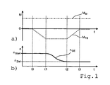
- FIG. 1 the process sequence according to the invention of a circuit-related load reduction and load build-up is exemplified for a pull upshift.
- Fig. 1 a shows the time courses of the engine torque M M delivered by the drive engine and the braking torque M TB received by the hydrodynamic clutch 4 or the hydrodynamic torque converter 14 and recorded by the turbine brake 12, 12 ', while in FIG Fig. 1b the time course of the input shaft speed n GE of the gearbox is shown.
- the input shaft 3 of the gearbox between the times t1 and t2 by an internal gear synchronizer or by the drive motor from the starting speed n start at the beginning of the upshift to the target speed n target for engaging the target gear is braked.
- the subsequent load build-up takes place in that the turbine brake 12, 12 'is completely opened again up to the time t3.
- the full engine torque M M is applied to the input shaft 3 of the gearbox again from the time t3.
- a collapse of the spontaneously deliverable by the drive motor under load engine torque M M which can occur in a turbocharged internal combustion engine after a reduction of the output engine torque M M performed during load build-up, is reliably prevented according to the method according to the invention.
Landscapes
- Engineering & Computer Science (AREA)
- General Engineering & Computer Science (AREA)
- Mechanical Engineering (AREA)
- Control Of Transmission Device (AREA)
Claims (9)
- Procédé de commande de changement de vitesses d'une boîte de vitesses automatisée, en amont de laquelle est monté un élément de démarrage et de freinage hydrodynamique (2, 2') muni d'une roue de pompe (5, 15) et d'une roue de turbine (6, 16), par le biais duquel l'arbre d'entrée (3) de la boîte de vitesses est en liaison avec l'arbre moteur (1) d'un moteur d'entraînement réalisé sous forme de moteur à combustion interne à turbocompresseur, dont la roue de pompe (5, 15) peut être connectée par le biais d'un embrayage de pontage (8, 8') directement à un arbre intermédiaire (9, 9') connecté à l'arbre d'entrée (3), et dont la roue de turbine (6, 16) peut être connectée par le biais d'un embrayage à roue libre (11, 11') à l'arbre intermédiaire (9, 9') et peut être freinée par le biais d'un frein de turbine (12, 12') par rapport à un boîtier (13, 13'), dans lequel, pendant un changement de vitesse en traction, défini comme un passage à la vitesse supérieure en traction ou un rétrogradage en traction, l'arbre d'entrée (3) de la boîte de vitesses est maintenu essentiellement sans couple par une réduction de charge se produisant au début du changement de vitesse, afin que le rapport en charge enclenché soit conçu essentiellement sans charge et que le rapport cible à enclencher soit synchronisé essentiellement sans charge et puisse être enclenché, caractérisé en ce que la réduction de charge se produit en maintenant le couple moteur MM fourni par le moteur d'entraînement en créant un couple résistant MTB de même ampleur dans l'élément de démarrage et de freinage hydrodynamique (2, 2'), en fermant au moins partiellement le frein de turbine (12, 12') au début du changement de vitesse en traction et en ajustant le couple MTB transmis par l'élément de démarrage et de freinage hydrodynamique (2, 2') au frein de turbine (12, 12') au couple moteur MM du moteur d'entraînement, défini par |MTB| = |MM|, et en ce que le frein de turbine (12, 12') est à nouveau complètement ouvert pour l'augmentation de la charge à la fin du changement de vitesse en traction.
- Procédé selon la revendication 1, caractérisé en ce que dans le cas d'un rétrogradage en traction, l'embrayage de pontage (8, 8') reste au moins en partie fermé, et en ce que la synchronisation du rapport cible s'effectue par une augmentation du régime du moteur d'entraînement.
- Procédé selon la revendication 1, caractérisé en ce que dans le cas d'un passage à la vitesse supérieure en traction, l'embrayage de pontage (8, 8') reste au moins en partie fermé, et en ce que la synchronisation du rapport cible s'effectue par une réduction du régime du moteur d'entraînement.
- Procédé selon la revendication 1, caractérisé en ce que dans le cas d'un rétrogradage en traction, l'embrayage de pontage (8, 8') est complètement ouvert, et en ce que la synchronisation du rapport cible est effectuée lorsque le frein de turbine (12, 12') est complètement fermé par un dispositif de synchronisation interne à la boîte de vitesses ou par une augmentation du régime du moteur d'entraînement en association avec une fermeture partielle de l'embrayage de pontage (8, 8').
- Procédé selon la revendication 1, caractérisé en ce que dans le cas d'un rétrogradage en traction, l'embrayage de pontage (8, 8') est complètement ouvert, et en ce que la synchronisation du rapport cible, lorsque le frein de turbine (12, 12') est partiellement fermé, s'effectue par une augmentation du régime du moteur d'entraînement.
- Procédé selon la revendication 1, caractérisé en ce que dans le cas d'un passage à la vitesse supérieure en traction, l'embrayage de pontage (8, 8') est complètement ouvert, et en ce que la synchronisation du rapport cible, lorsque le frein de turbine (12, 12') est complètement fermé, s'effectue par un dispositif de synchronisation interne à la boîte de vitesses ou par une réduction du régime du moteur d'entraînement en association avec une fermeture partielle de l'embrayage de pontage (8, 8').
- Procédé selon la revendication 1, caractérisé en ce que dans le cas d'un passage à la vitesse supérieure en traction, l'embrayage de pontage (8, 8') est complètement ouvert, et en ce que la synchronisation du rapport cible, lorsque le frein de turbine (12, 12') est partiellement fermé, s'effectue par un dispositif de synchronisation interne à la boîte de vitesses avec guidage du régime de l'arbre d'entrée nGE au-dessus du régime de la roue de turbine nT, défini par nGE > nT, ou par une réduction du régime du moteur d'entraînement en association avec une fermeture partielle de l'embrayage de pontage (8, 8').
- Procédé selon l'une quelconque des revendications 2, 4 et 5, caractérisé en ce que l'augmentation du régime du moteur est provoquée par une augmentation brève du couple MM du moteur d'entraînement et/ou par une réduction brève du couple MTB transmis par l'élément de démarrage et de freinage hydrodynamique (2, 2') et/ou par une ouverture brève ou une ouverture supplémentaire du frein de turbine (12, 12').
- Procédé selon l'une quelconque des revendications 3, 6 et 7, caractérisé en ce que la réduction du régime du moteur est provoquée par une réduction brève du couple MM du moteur d'entraînement et/ou par une augmentation brève du couple MTB transmis par l'élément de démarrage et de freinage hydrodynamique (2, 2') et, lorsque le frein de turbine (12, 12') est partiellement fermé, en plus par une fermeture brève supplémentaire du frein de turbine (12, 12').
Applications Claiming Priority (1)
| Application Number | Priority Date | Filing Date | Title |
|---|---|---|---|
| DE102010028076A DE102010028076A1 (de) | 2010-04-22 | 2010-04-22 | Verfahren zur Schaltsteuerung eines automatisierten Schaltgetriebes |
Publications (2)
| Publication Number | Publication Date |
|---|---|
| EP2381140A1 EP2381140A1 (fr) | 2011-10-26 |
| EP2381140B1 true EP2381140B1 (fr) | 2012-08-22 |
Family
ID=43903382
Family Applications (1)
| Application Number | Title | Priority Date | Filing Date |
|---|---|---|---|
| EP20110156606 Not-in-force EP2381140B1 (fr) | 2010-04-22 | 2011-03-02 | Procédé de commande de changement de vitesse d'une boîte de vitesse automatisée |
Country Status (2)
| Country | Link |
|---|---|
| EP (1) | EP2381140B1 (fr) |
| DE (1) | DE102010028076A1 (fr) |
Families Citing this family (5)
| Publication number | Priority date | Publication date | Assignee | Title |
|---|---|---|---|---|
| DE102010042267A1 (de) | 2010-10-11 | 2012-04-12 | Zf Friedrichshafen Ag | Verfahren zur Steuerung von Schaltungen eines Teildoppelkupplungsgetriebes |
| DE102011079392A1 (de) | 2011-07-19 | 2013-01-24 | Zf Friedrichshafen Ag | Verfahren zur Schaltsteuerung eines automatisierten Schaltgetriebes |
| DE102012012499B4 (de) * | 2012-06-21 | 2016-08-04 | Volkswagen Aktiengesellschaft | Verfahren und Vorrichtung zur Schaltsteuerung eines Kraftfahrzeugs |
| DE102017128377A1 (de) * | 2017-11-30 | 2019-06-06 | Voith Patent Gmbh | Antriebsstrang |
| CN114110159A (zh) * | 2021-11-03 | 2022-03-01 | 江苏汇智高端工程机械创新中心有限公司 | 一种越野轮胎起重机变速箱挡位控制方法及系统 |
Family Cites Families (4)
| Publication number | Priority date | Publication date | Assignee | Title |
|---|---|---|---|---|
| DE6915757U (de) * | 1969-04-19 | 1975-05-07 | Voith Getriebe Kg | Hydrodynamisches vorsatzgetriebe fuer ein wechselgetriebe. |
| DE10045337A1 (de) | 2000-09-08 | 2002-03-21 | Voith Turbo Kg | Anfahreinheit |
| DE102004059733A1 (de) * | 2004-12-11 | 2006-06-14 | Voith Turbo Gmbh & Co. Kg | Getriebebaueinheit |
| DE102004059744A1 (de) * | 2004-12-11 | 2006-06-14 | Voith Turbo Gmbh & Co. Kg | Getriebebaueinheit |
-
2010
- 2010-04-22 DE DE102010028076A patent/DE102010028076A1/de not_active Withdrawn
-
2011
- 2011-03-02 EP EP20110156606 patent/EP2381140B1/fr not_active Not-in-force
Also Published As
| Publication number | Publication date |
|---|---|
| EP2381140A1 (fr) | 2011-10-26 |
| DE102010028076A1 (de) | 2011-10-27 |
Similar Documents
| Publication | Publication Date | Title |
|---|---|---|
| DE19631983C1 (de) | Verfahren zum Schalten eines Doppelkupplungsgetriebes und Doppelkupplungsgetriebe mit Synchronisiereinrichtung | |
| EP2619482B1 (fr) | Procédé de commande de changements de vitesse d'une boîte de vitesses de véhicule | |
| EP2118527B1 (fr) | Procédé destiné à faire fonctionner la chaîne cinématique d'un véhicule | |
| EP2627932B1 (fr) | Procédé de commande de chaîne cinématique | |
| EP1551662B1 (fr) | Procede de commande des changements de rapports d'une boite couplable sous charge et boite de vitesses couplable sous charge | |
| EP3668737B1 (fr) | Ensemble boîte de vitesses de motorisation hybride et procédé pour faire fonctionner un véhicule à motorisation hybride | |
| EP2836403B1 (fr) | Élément de démarrage et de ralentissement ainsi que procédé permettant de faire fonctionner un élément de démarrage et de ralentissement | |
| WO2010115806A1 (fr) | Procédé pour faire fonctionner une chaîne cinématique de véhicule à moteur | |
| DE102014016932A1 (de) | Verfahren zum Schalten eines Gruppengetriebes eines Kraftwagens | |
| EP2178714A2 (fr) | Procédé pour effectuer un changement de vitesse en charge pour des véhicules à propulsion électrique | |
| DE102010030242A1 (de) | Verfahren zum Schalten zumindest einer Über- oder Untersetzungsstufe bei einem Verteilergetriebe | |
| EP2123941A1 (fr) | Boîte de vitesse à plusieurs groupes d'un véhicule automobile | |
| DE102009045485A1 (de) | Verfahren zum Betreiben einer Antriebsvorrichtung, Antriebsvorrichtung | |
| DE102011079392A1 (de) | Verfahren zur Schaltsteuerung eines automatisierten Schaltgetriebes | |
| EP2381140B1 (fr) | Procédé de commande de changement de vitesse d'une boîte de vitesse automatisée | |
| DE10114880A1 (de) | Getriebe | |
| EP2381134B1 (fr) | Procédé de commande de changement de vitesse d'une boîte de vitesse automatisée | |
| DE19845604C5 (de) | Stufengetriebe und Verfahren zum Auslegen eines Ganges eines Stufengetriebes | |
| DE102019216464A1 (de) | Automatisches Schaltgetriebe für Kraftfahrzeuge | |
| WO2007085359A1 (fr) | Procédé de commande d'une chaîne cinématique de véhicule à moteur | |
| DE102011088855B4 (de) | Verfahren zur Steuerung einer Wandlerschaltkupplung | |
| DE102010028935A1 (de) | Verfahren zum Betreiben eines Antriebsstrangs | |
| DE10063848A1 (de) | Stufenschaltgetriebe für ein Kraftfahrzeug | |
| DE19627895C1 (de) | Zahnräderwechselgetriebe | |
| DE102011088853A1 (de) | Verfahren zur Steuerung einer Wandlerschaltkupplung |
Legal Events
| Date | Code | Title | Description |
|---|---|---|---|
| AK | Designated contracting states |
Kind code of ref document: A1 Designated state(s): AL AT BE BG CH CY CZ DE DK EE ES FI FR GB GR HR HU IE IS IT LI LT LU LV MC MK MT NL NO PL PT RO RS SE SI SK SM TR |
|
| AX | Request for extension of the european patent |
Extension state: BA ME |
|
| PUAI | Public reference made under article 153(3) epc to a published international application that has entered the european phase |
Free format text: ORIGINAL CODE: 0009012 |
|
| 17P | Request for examination filed |
Effective date: 20111212 |
|
| GRAP | Despatch of communication of intention to grant a patent |
Free format text: ORIGINAL CODE: EPIDOSNIGR1 |
|
| RIC1 | Information provided on ipc code assigned before grant |
Ipc: F16H 61/14 20060101ALN20120220BHEP Ipc: F16H 45/02 20060101ALN20120220BHEP Ipc: F16H 61/02 20060101AFI20120220BHEP |
|
| GRAS | Grant fee paid |
Free format text: ORIGINAL CODE: EPIDOSNIGR3 |
|
| GRAA | (expected) grant |
Free format text: ORIGINAL CODE: 0009210 |
|
| AK | Designated contracting states |
Kind code of ref document: B1 Designated state(s): AL AT BE BG CH CY CZ DE DK EE ES FI FR GB GR HR HU IE IS IT LI LT LU LV MC MK MT NL NO PL PT RO RS SE SI SK SM TR |
|
| REG | Reference to a national code |
Ref country code: GB Ref legal event code: FG4D Free format text: NOT ENGLISH |
|
| REG | Reference to a national code |
Ref country code: CH Ref legal event code: EP |
|
| REG | Reference to a national code |
Ref country code: IE Ref legal event code: FG4D Free format text: LANGUAGE OF EP DOCUMENT: GERMAN |
|
| REG | Reference to a national code |
Ref country code: AT Ref legal event code: REF Ref document number: 572177 Country of ref document: AT Kind code of ref document: T Effective date: 20120915 |
|
| REG | Reference to a national code |
Ref country code: DE Ref legal event code: R096 Ref document number: 502011000071 Country of ref document: DE Effective date: 20121018 |
|
| REG | Reference to a national code |
Ref country code: SE Ref legal event code: TRGR |
|
| REG | Reference to a national code |
Ref country code: NL Ref legal event code: VDEP Effective date: 20120822 |
|
| REG | Reference to a national code |
Ref country code: LT Ref legal event code: MG4D Effective date: 20120822 |
|
| PG25 | Lapsed in a contracting state [announced via postgrant information from national office to epo] |
Ref country code: FI Free format text: LAPSE BECAUSE OF FAILURE TO SUBMIT A TRANSLATION OF THE DESCRIPTION OR TO PAY THE FEE WITHIN THE PRESCRIBED TIME-LIMIT Effective date: 20120822 Ref country code: HR Free format text: LAPSE BECAUSE OF FAILURE TO SUBMIT A TRANSLATION OF THE DESCRIPTION OR TO PAY THE FEE WITHIN THE PRESCRIBED TIME-LIMIT Effective date: 20120822 Ref country code: LT Free format text: LAPSE BECAUSE OF FAILURE TO SUBMIT A TRANSLATION OF THE DESCRIPTION OR TO PAY THE FEE WITHIN THE PRESCRIBED TIME-LIMIT Effective date: 20120822 Ref country code: NO Free format text: LAPSE BECAUSE OF FAILURE TO SUBMIT A TRANSLATION OF THE DESCRIPTION OR TO PAY THE FEE WITHIN THE PRESCRIBED TIME-LIMIT Effective date: 20121122 Ref country code: IS Free format text: LAPSE BECAUSE OF FAILURE TO SUBMIT A TRANSLATION OF THE DESCRIPTION OR TO PAY THE FEE WITHIN THE PRESCRIBED TIME-LIMIT Effective date: 20121222 |
|
| PG25 | Lapsed in a contracting state [announced via postgrant information from national office to epo] |
Ref country code: SI Free format text: LAPSE BECAUSE OF FAILURE TO SUBMIT A TRANSLATION OF THE DESCRIPTION OR TO PAY THE FEE WITHIN THE PRESCRIBED TIME-LIMIT Effective date: 20120822 Ref country code: GR Free format text: LAPSE BECAUSE OF FAILURE TO SUBMIT A TRANSLATION OF THE DESCRIPTION OR TO PAY THE FEE WITHIN THE PRESCRIBED TIME-LIMIT Effective date: 20121123 Ref country code: LV Free format text: LAPSE BECAUSE OF FAILURE TO SUBMIT A TRANSLATION OF THE DESCRIPTION OR TO PAY THE FEE WITHIN THE PRESCRIBED TIME-LIMIT Effective date: 20120822 Ref country code: PT Free format text: LAPSE BECAUSE OF FAILURE TO SUBMIT A TRANSLATION OF THE DESCRIPTION OR TO PAY THE FEE WITHIN THE PRESCRIBED TIME-LIMIT Effective date: 20121224 |
|
| PG25 | Lapsed in a contracting state [announced via postgrant information from national office to epo] |
Ref country code: NL Free format text: LAPSE BECAUSE OF FAILURE TO SUBMIT A TRANSLATION OF THE DESCRIPTION OR TO PAY THE FEE WITHIN THE PRESCRIBED TIME-LIMIT Effective date: 20120822 |
|
| PG25 | Lapsed in a contracting state [announced via postgrant information from national office to epo] |
Ref country code: DK Free format text: LAPSE BECAUSE OF FAILURE TO SUBMIT A TRANSLATION OF THE DESCRIPTION OR TO PAY THE FEE WITHIN THE PRESCRIBED TIME-LIMIT Effective date: 20120822 Ref country code: RO Free format text: LAPSE BECAUSE OF FAILURE TO SUBMIT A TRANSLATION OF THE DESCRIPTION OR TO PAY THE FEE WITHIN THE PRESCRIBED TIME-LIMIT Effective date: 20120822 Ref country code: EE Free format text: LAPSE BECAUSE OF FAILURE TO SUBMIT A TRANSLATION OF THE DESCRIPTION OR TO PAY THE FEE WITHIN THE PRESCRIBED TIME-LIMIT Effective date: 20120822 Ref country code: CZ Free format text: LAPSE BECAUSE OF FAILURE TO SUBMIT A TRANSLATION OF THE DESCRIPTION OR TO PAY THE FEE WITHIN THE PRESCRIBED TIME-LIMIT Effective date: 20120822 |
|
| PG25 | Lapsed in a contracting state [announced via postgrant information from national office to epo] |
Ref country code: PL Free format text: LAPSE BECAUSE OF FAILURE TO SUBMIT A TRANSLATION OF THE DESCRIPTION OR TO PAY THE FEE WITHIN THE PRESCRIBED TIME-LIMIT Effective date: 20120822 Ref country code: IT Free format text: LAPSE BECAUSE OF FAILURE TO SUBMIT A TRANSLATION OF THE DESCRIPTION OR TO PAY THE FEE WITHIN THE PRESCRIBED TIME-LIMIT Effective date: 20120822 Ref country code: SK Free format text: LAPSE BECAUSE OF FAILURE TO SUBMIT A TRANSLATION OF THE DESCRIPTION OR TO PAY THE FEE WITHIN THE PRESCRIBED TIME-LIMIT Effective date: 20120822 |
|
| PLBE | No opposition filed within time limit |
Free format text: ORIGINAL CODE: 0009261 |
|
| STAA | Information on the status of an ep patent application or granted ep patent |
Free format text: STATUS: NO OPPOSITION FILED WITHIN TIME LIMIT |
|
| 26N | No opposition filed |
Effective date: 20130523 |
|
| PG25 | Lapsed in a contracting state [announced via postgrant information from national office to epo] |
Ref country code: BG Free format text: LAPSE BECAUSE OF FAILURE TO SUBMIT A TRANSLATION OF THE DESCRIPTION OR TO PAY THE FEE WITHIN THE PRESCRIBED TIME-LIMIT Effective date: 20121122 Ref country code: RS Free format text: LAPSE BECAUSE OF FAILURE TO SUBMIT A TRANSLATION OF THE DESCRIPTION OR TO PAY THE FEE WITHIN THE PRESCRIBED TIME-LIMIT Effective date: 20120822 |
|
| REG | Reference to a national code |
Ref country code: DE Ref legal event code: R097 Ref document number: 502011000071 Country of ref document: DE Effective date: 20130523 |
|
| BERE | Be: lapsed |
Owner name: ZF FRIEDRICHSHAFEN A.G. Effective date: 20130331 |
|
| PG25 | Lapsed in a contracting state [announced via postgrant information from national office to epo] |
Ref country code: ES Free format text: LAPSE BECAUSE OF FAILURE TO SUBMIT A TRANSLATION OF THE DESCRIPTION OR TO PAY THE FEE WITHIN THE PRESCRIBED TIME-LIMIT Effective date: 20121203 Ref country code: MC Free format text: LAPSE BECAUSE OF NON-PAYMENT OF DUE FEES Effective date: 20130331 |
|
| PG25 | Lapsed in a contracting state [announced via postgrant information from national office to epo] |
Ref country code: CY Free format text: LAPSE BECAUSE OF FAILURE TO SUBMIT A TRANSLATION OF THE DESCRIPTION OR TO PAY THE FEE WITHIN THE PRESCRIBED TIME-LIMIT Effective date: 20120822 |
|
| REG | Reference to a national code |
Ref country code: FR Ref legal event code: ST Effective date: 20131129 |
|
| REG | Reference to a national code |
Ref country code: IE Ref legal event code: MM4A |
|
| PG25 | Lapsed in a contracting state [announced via postgrant information from national office to epo] |
Ref country code: IE Free format text: LAPSE BECAUSE OF NON-PAYMENT OF DUE FEES Effective date: 20130302 Ref country code: AL Free format text: LAPSE BECAUSE OF FAILURE TO SUBMIT A TRANSLATION OF THE DESCRIPTION OR TO PAY THE FEE WITHIN THE PRESCRIBED TIME-LIMIT Effective date: 20120822 Ref country code: BE Free format text: LAPSE BECAUSE OF NON-PAYMENT OF DUE FEES Effective date: 20130331 Ref country code: FR Free format text: LAPSE BECAUSE OF NON-PAYMENT OF DUE FEES Effective date: 20130402 |
|
| PG25 | Lapsed in a contracting state [announced via postgrant information from national office to epo] |
Ref country code: MT Free format text: LAPSE BECAUSE OF FAILURE TO SUBMIT A TRANSLATION OF THE DESCRIPTION OR TO PAY THE FEE WITHIN THE PRESCRIBED TIME-LIMIT Effective date: 20120822 |
|
| REG | Reference to a national code |
Ref country code: CH Ref legal event code: PL |
|
| PG25 | Lapsed in a contracting state [announced via postgrant information from national office to epo] |
Ref country code: LI Free format text: LAPSE BECAUSE OF NON-PAYMENT OF DUE FEES Effective date: 20140331 Ref country code: CH Free format text: LAPSE BECAUSE OF NON-PAYMENT OF DUE FEES Effective date: 20140331 |
|
| PG25 | Lapsed in a contracting state [announced via postgrant information from national office to epo] |
Ref country code: SM Free format text: LAPSE BECAUSE OF FAILURE TO SUBMIT A TRANSLATION OF THE DESCRIPTION OR TO PAY THE FEE WITHIN THE PRESCRIBED TIME-LIMIT Effective date: 20120822 |
|
| PG25 | Lapsed in a contracting state [announced via postgrant information from national office to epo] |
Ref country code: TR Free format text: LAPSE BECAUSE OF FAILURE TO SUBMIT A TRANSLATION OF THE DESCRIPTION OR TO PAY THE FEE WITHIN THE PRESCRIBED TIME-LIMIT Effective date: 20120822 |
|
| PG25 | Lapsed in a contracting state [announced via postgrant information from national office to epo] |
Ref country code: LU Free format text: LAPSE BECAUSE OF NON-PAYMENT OF DUE FEES Effective date: 20130302 Ref country code: HU Free format text: LAPSE BECAUSE OF FAILURE TO SUBMIT A TRANSLATION OF THE DESCRIPTION OR TO PAY THE FEE WITHIN THE PRESCRIBED TIME-LIMIT; INVALID AB INITIO Effective date: 20110302 Ref country code: MK Free format text: LAPSE BECAUSE OF FAILURE TO SUBMIT A TRANSLATION OF THE DESCRIPTION OR TO PAY THE FEE WITHIN THE PRESCRIBED TIME-LIMIT Effective date: 20120822 |
|
| GBPC | Gb: european patent ceased through non-payment of renewal fee |
Effective date: 20150302 |
|
| PG25 | Lapsed in a contracting state [announced via postgrant information from national office to epo] |
Ref country code: GB Free format text: LAPSE BECAUSE OF NON-PAYMENT OF DUE FEES Effective date: 20150302 |
|
| PGFP | Annual fee paid to national office [announced via postgrant information from national office to epo] |
Ref country code: SE Payment date: 20160311 Year of fee payment: 6 |
|
| REG | Reference to a national code |
Ref country code: AT Ref legal event code: MM01 Ref document number: 572177 Country of ref document: AT Kind code of ref document: T Effective date: 20160302 |
|
| PG25 | Lapsed in a contracting state [announced via postgrant information from national office to epo] |
Ref country code: AT Free format text: LAPSE BECAUSE OF NON-PAYMENT OF DUE FEES Effective date: 20160302 |
|
| REG | Reference to a national code |
Ref country code: SE Ref legal event code: EUG |
|
| PG25 | Lapsed in a contracting state [announced via postgrant information from national office to epo] |
Ref country code: SE Free format text: LAPSE BECAUSE OF NON-PAYMENT OF DUE FEES Effective date: 20170303 |
|
| P01 | Opt-out of the competence of the unified patent court (upc) registered |
Effective date: 20230528 |
|
| PGFP | Annual fee paid to national office [announced via postgrant information from national office to epo] |
Ref country code: DE Payment date: 20231229 Year of fee payment: 14 |
|
| REG | Reference to a national code |
Ref country code: DE Ref legal event code: R119 Ref document number: 502011000071 Country of ref document: DE |
|
| PG25 | Lapsed in a contracting state [announced via postgrant information from national office to epo] |
Ref country code: DE Free format text: LAPSE BECAUSE OF NON-PAYMENT OF DUE FEES Effective date: 20251001 |