EP2381165B1 - Phare pour véhicules - Google Patents
Phare pour véhicules Download PDFInfo
- Publication number
- EP2381165B1 EP2381165B1 EP11162034.0A EP11162034A EP2381165B1 EP 2381165 B1 EP2381165 B1 EP 2381165B1 EP 11162034 A EP11162034 A EP 11162034A EP 2381165 B1 EP2381165 B1 EP 2381165B1
- Authority
- EP
- European Patent Office
- Prior art keywords
- light
- depressions
- diaphragm shaft
- focal line
- shaft
- Prior art date
- Legal status (The legal status is an assumption and is not a legal conclusion. Google has not performed a legal analysis and makes no representation as to the accuracy of the status listed.)
- Active
Links
Images



Classifications
-
- F—MECHANICAL ENGINEERING; LIGHTING; HEATING; WEAPONS; BLASTING
- F21—LIGHTING
- F21S—NON-PORTABLE LIGHTING DEVICES; SYSTEMS THEREOF; VEHICLE LIGHTING DEVICES SPECIALLY ADAPTED FOR VEHICLE EXTERIORS
- F21S41/00—Illuminating devices specially adapted for vehicle exteriors, e.g. headlamps
- F21S41/60—Illuminating devices specially adapted for vehicle exteriors, e.g. headlamps characterised by a variable light distribution
- F21S41/68—Illuminating devices specially adapted for vehicle exteriors, e.g. headlamps characterised by a variable light distribution by acting on screens
- F21S41/683—Illuminating devices specially adapted for vehicle exteriors, e.g. headlamps characterised by a variable light distribution by acting on screens by moving screens
- F21S41/698—Shaft-shaped screens rotating along its longitudinal axis
-
- F—MECHANICAL ENGINEERING; LIGHTING; HEATING; WEAPONS; BLASTING
- F21—LIGHTING
- F21S—NON-PORTABLE LIGHTING DEVICES; SYSTEMS THEREOF; VEHICLE LIGHTING DEVICES SPECIALLY ADAPTED FOR VEHICLE EXTERIORS
- F21S41/00—Illuminating devices specially adapted for vehicle exteriors, e.g. headlamps
- F21S41/40—Illuminating devices specially adapted for vehicle exteriors, e.g. headlamps characterised by screens, non-reflecting members, light-shielding members or fixed shades
- F21S41/43—Illuminating devices specially adapted for vehicle exteriors, e.g. headlamps characterised by screens, non-reflecting members, light-shielding members or fixed shades characterised by the shape thereof
Definitions
- the invention relates to a headlamp for vehicles with a reflector, a lens and arranged between the reflector and the lens aperture shaft which is adjustable about a horizontal and transverse to the optical axis axis of rotation in two or more rotational positions, and wherein the lateral surface of the aperture shaft for each rotational position at least in each case has a focal line which generates a light-dark boundary of a light distribution, and wherein a section of the lateral surface of the diaphragm shaft is designed to generate one or more focal lines for partial remote light, each focal line for partial remote light having a first linear focal line section, which is located in a first cladding region of the diaphragm shaft, which is curved in the rotational or circumferential direction of the diaphragm shaft, for example is cylindrical, and wherein a second rectilinear focal line section is located in a second, for example, substantially flat shell region of the diaphragm shaft, and wherein the second cladding region has a smaller distance from the axi
- Aperture shafts which, among other things, have one or more focal lines for partial remote light are known, for example from US Pat EP 2 157 362 A1 .
- the "normal" high beam distribution hides / shadows an area of the light distribution in which vehicles or persons are located. If, for example, the vehicle is traveling with high-beam distribution, for example due to high speed on the highway, and a vehicle appears on its own roadway in front of the vehicle, only that area of the light distribution in which this emerged vehicle is located can be darkened. A dimming as usual is not necessary in this case.
- this area can be darkened, in which the oncoming traffic vehicle is located, while the remaining area of the light distribution is illuminated in accordance with the "normal" high beam distribution.
- a diaphragm shaft has at least two focal line sections or two lateral regions as described above. In the vertical direction, the two focal line sections merge into one another via a jump. Inevitably, as a result of the spatial extent of the diaphragm shaft in the light exit direction thus results in a jump surface in the diaphragm shaft, which depending on the specific design of the focal lines for Operafernlicht either flat or as well as from the EP 2 157 362 A1 may be formed curved.
- the jump surface has a plurality of depressions.
- these depressions on the jump surface By means of these depressions on the jump surface, light beams which are otherwise blocked and do not enter the outer space can reach the outer space in a controlled manner and thus illuminate the otherwise undesirably shaded area.
- light rays can enter the area to be illuminated in the outer space of the headlamp, if the recesses are designed to extend in the light exit direction, in particular, when the diaphragm shaft is in a rotational position in which a focal line for partial remote light is optically effective, ie their focal line is displayed as a HD line in the light image (the light-dark line being sharply imaged only in that area in which light is shaded).
- Oblong means that the depressions are longer than they are wider; the depressions are formed in the form of grooves in the jump surface; the edges or areas between two grooves are at the same height as the rest of the jump surface.
- the recesses extend from a front, the reflector facing away from the end of the aperture shaft to the rear in the direction of the reflector facing the end.
- a light beam entering a recess / groove can pass through the depression and emerge from the depression at the end of the depression and reach the exterior of the headlight.
- the elongated depressions seen in the light exit direction on increasing cross-sectional areas.
- the grooves become wider toward their free, lens-facing end.
- at least two adjacent elongated depressions directly adjoin one another.
- the recesses / grooves are separated in this case by a sharp edge or by a rounded transition (the highest point of the transition is on the jump surface or is part of the jump surface).
- the groove-shaped recesses are separated by a distance which may vary along the grooves.
- the area between the recesses in this case is flat (in the case of a flat jump surface), or it is again provided a rounded transition.
- the elongated depressions extend parallel to one another.
- the depressions can also run apart, for example, in the direction of the lens.
- the recesses are at least partially formed differently deep different heights.
- the depressions have different depths seen over their lengths.
- the groove becomes deeper toward the lens.
- the grooves may be less deep on the reflector side than on the lens side.
- different elongated depressions have different depths.
- the jump surface is flat.
- a flat jump surface has the advantage that the light-dark line in the shaded area can be raised or lowered by twisting the shutter shaft (for this purpose, the lateral surface must be formed with differently high focal lines), but at the same time the transition to the high beam area in the Generalfernlichtver gutter remains unaffected ie In this area, the light distribution does not change when the diaphragm shaft is rotated.
- the recesses extend over a range which corresponds to about one third to two thirds of the height of the jump surface.
- the "height" of the jump surface is the normal distance between the second lateral surface and the highest focal line in the first lateral surface.
- the region over which the depressions extend in the jump surface is spaced from the first lateral surface and / or the second lateral surface.
- the grooves extend approximately equally far up and down.
- the whole surface is not provided with grooves.
- the grooves are preferably located approximately in the middle third of the surface. If one rilled the whole surface, the effect of a light concentration in the darkened area would occur.
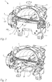
- FIG. 1 shows a vehicle headlight (projection system) 1 with an aperture shaft 11 according to the invention.
- the headlight 1 has a lens 4 (see FIG. 5d ) mounted in, for example, a lens holder (not shown).
- the lens holder and thus the lens 4 may be pivotable about a vertical axis 300.
- a number of the proposed modifications to the diaphragm shaft 11 according to the invention are also of importance for non-pivotable lens projection systems; if a modification especially or exclusively for a pivotable about a vertical axis 300 lens 4 is relevant, this is explicitly indicated in the text.
- the headlight 1 further has a light source 4a and a reflector 3, which is installed in the variant shown in an adapter 2. Attached to this adapter 2 are all relevant parts, such as a drive means 5 (for example a stepper motor) for rotating the aperture shaft 11 about its axis of rotation 100.
- the axis of rotation 100 is centered on the aperture shaft, i. not eccentric.
- the light source 4a or the center of the helix of the light source is mounted in a first focal point of the reflector, the diaphragm shaft 11 is arranged such that focal lines of the diaphragm shaft 11 extend through a second focus of the reflector.
- the lens 4 is arranged such that a focal point of the lens or its focal line extends through the second focal point of the reflector.
- the reference numeral 10 designates the entire diaphragm arrangement in the headlight 1, which also includes an (additional) diaphragm or a shading device 6 in addition to the diaphragm shaft 11.
- This shader 6 absorbs light rays that would escape below the aperture 11.
- the upper edge 6 'of the Abschatters 6 preferably extends in height or slightly above the axis of rotation 100 of the shaft.
- the diaphragm shaft 11 is rotatably mounted on the adapter 2.
- the adapter 2 forms a part of a bearing shell 8 and the shading device 6 the second part 7 of this bearing shell.
- a ball bearing 9 for the axis of rotation 100 of the diaphragm shaft 11 is held in this bearing shell.
- the storage can in principle also directly, so without ball bearings, take place on the adapter, e.g. via a clip connection, etc.
- the wear on the adapter caused by the rotation of the shaft can be minimized.
- the shaft itself may consist of temperature-resistant plastic, ceramic, metal and the like.
- FIG. 2 shows again the arrangement FIG. 1 , with removed shading device 6.
- the diaphragm shaft 11 is about the horizontal and transverse to the optical axis 200 extending axis of rotation 100 in two or more rotational positions adjustable, wherein the lateral surface 12 of the diaphragm shaft 11 for each rotational position at least each having a focal line, which generates a light-dark boundary of a light distribution ,
- FIG. 3a shows, for example, a region of the lateral surface 12 with a plurality of focal lines 20 for producing a dimmed light distribution in the form of a low beam and with a plurality of focal lines 21 for producing a dimmed light distribution in the form of a motorway light. It can also be seen a focal line 22 for generating a high beam distribution.
- FIG. 3b It can be seen that the diaphragm shaft 11 is in a position in which one of the focal lines 20 for dipped beam is active, ie this focal line generates the light-dark boundary of the light distribution in the light image.
- Figure 3c a corresponding low-beam light distribution 1000 is shown with light-dark boundary 1001.
- FIG. 4a shows the shaft 11 as off FIG. 3a rotated a bit further, so now one of the focal lines 21 is active for another dimmed light distribution such as motorway light.
- Figure 4c shows such a highway light distribution 2000 with the light-dark boundary 2001, which is generated by the focal line 21.
- Aperture shafts for generating different light images for vehicle headlights are well known. Due to the extent of such a diaphragm shaft extending in the light exit direction, in contrast to a flat diaphragm which has a negligible extent in the light exit direction (small thickness, thin diaphragm), the problem arises that light reflected by the reflector is directed into an upper diaphragm. reaches undesirable area of the lateral surface of the diaphragm shaft and is emitted from there as unwanted scattered light, which may lead to glare or legally not allowed values in the photograph, is emitted into the outer space. This problem also exists with thin aperture shafts with a small diameter, since these also have a certain extent in the light exit direction.
- dimmed light distribution are, for example, dipped beam (symmetrical, asymmetrical), motorway light, city light. These light distributions are e.g. defined in the ECE / SAE regulation.
- the problem of unwanted stray light is in the US 2009/0154187 A1 thematized, which shows an aperture diaphragm mentioned above.
- the diaphragm shaft shown in this document has grooves which are distributed at intervals to each other over a part of the lateral surface of the diaphragm shaft and extending over at least a full half of the diaphragm shaft (seen along the axis of rotation).
- the lateral surface 12 of the diaphragm shaft 11 in the region of at least one focal line 20, 21 for dimmed light grooves 30th , 31, 32, 33, 34, 35, which run approximately parallel to the axis of rotation 100 of the diaphragm shaft 11, wherein viewed in the rotational or circumferential direction of the diaphragm shaft 11, adjacent grooves 30, 31; 31, 32; 32, 33; 33, 34; 34, 35 directly adjoin one another and are separated from each other by a common edge 40, 41, 42, 43, 44.
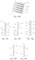
- These grooves are in FIG. 3a and 4a to recognize and especially in FIG. 8a and in detail in the Figures 9a, 9b and 9c shown.
- the diaphragm shaft 11 shown in the figures has areas for dipped beam as well as motorway light, accordingly, it is favorable if the ribs are provided in both areas as shown.
- FIGS. 9a-9c Due to the ribs, light which passes too steeply from above onto the diaphragm shaft is "captured" by the ribs and, for example, scattered back into the headlight, so that unwanted scattered radiation can no longer occur or can be significantly reduced.
- FIG. 9a shows a beam which strikes a portion of the lateral surface of the diaphragm shaft, which is smooth, so has no grooves, this beam is deflected into the outer space of the headlight, while the incident on the ribs beam is directed back into the headlight.
- the shaft may have a black, light-absorbing surface, thereby the scattered light can be further reduced.
- the diaphragm shaft 11 points in the circumferential direction, ie in the direction of rotation, in a defined rotational angle range ⁇ (FIG. FIG. 8a . FIG. 9a ), a lateral surface 12 with a configuration for forming a focal line region for a plurality of focal lines 20, 21 for dimmed light, wherein a plurality of grooves in this rotation angle range ⁇ of the lateral surface 12 are arranged.
- the aperture shaft has a plurality of adjacent focal lines of the same kind (that is, a plurality of low-beam focal lines, etc.), it is only necessary to produce the dimming beam so that the dimming shaft is positioned so that one of the dimming beam focal lines is active.
- the required focal lines are distributed at the "mantle" surface of the diaphragm shaft.
- each type has a 60 ° segment of the lateral surface (with even distribution, other distributions possible).
- Using only a small angular range for one type of focal line one has much useless surface on the mantle of the diaphragm shaft, which is unfavorable. Therefore, it makes sense to take advantage of full 60 ° for a focal line, which also gains operational safety.
- the minimum diameter of the shaft is mainly defined by the height of the HD line in high beam.
- a diaphragm shaft with at least 12 mm diameter. Add to this is still the space that takes the axis of rotation to complete. Assuming 5 mm diameter for the rotation axis (rotating shaft), the diaphragm shaft reaches a diameter of about 17 mm.
- adjacent grooves adjacent to each other directly and are separated by an edge.
- FIGS. 9a-9c cuts through the diaphragm shaft 11 after FIG. 3b according to the lines AA, BB and CC show.
- edges 40, 41, 42, 43, 44 are sharp edges. So it should be strived to produce as sharp edges as possible, i. produce as sharp-edged transitions between adjacent grooves in order to produce as little scattered radiation. In practice, this sharp-edged course, of course, set certain limits, depending on the material more or less rounded edges can be formed, so rounded transitions between the grooves, in which case then seek to make the corresponding radii small.
- the edge 45 delimits the last groove 35.
- the grooves may also be along a curved curve, e.g. corresponding to the focal line of the lens, which is also curved, run. This can achieve the best optical effect in the form of a sharper HD line, but the production is very complex.
- the grooves 30, 31, 32, 33, 34, 35 are preferably arranged in a substantially central region 12m of the diaphragm shaft 11, as seen along the axis of rotation 100 (see FIG. 8b ).
- the reflector "concentrates" the light substantially in a central region, so that the strongest stray radiation substantially from the central region of the Aperture comes. It is therefore not absolutely necessary to provide grooves outside the central area of the diaphragm shaft, and blackening of the shaft is generally sufficient in these areas.
- the dimmed light focal lines 20, 21 each have a first focal line section 20a, 21a which is rectilinear and parallel to the axis of rotation 100, and a second focal line section 20b, 21b which is also rectilinear and parallel to the axis of rotation 100 ,
- the two sections 20a, 20b; 21a, 21b are connected via a third focal line section 20c, 21c extending rectilinearly and obliquely to the axis of rotation 100, and the first focal line section 21a has a greater normal distance from the axis of rotation 100 than the second focal line section 20b.
- the grooves 30, 31, 32, 33, 34, 35 extend, starting from the focal line section 20c extending obliquely to the axis of rotation 100; 21c, over a distance d in the first and / or the second focal line portion 20a, 21a; 20b, 21b, preferably into both focal line sections, as shown.
- the distance d of the extension into the focal line sections 20a, 21a; 20b, 21b into approximately corresponds to an angle range of +/- 10 ° (measured from the center of the light source). Basically, however, this numerical value depends on the reflector, this has a small maximum, i. a strong concentration of light in the middle, then an extension of 10 ° may well be sufficient. If the reflector has a very wide maximum range, more than 30 °, e.g. 45 ° on both sides necessary.
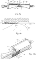
- FIG. 5d shows a vertical section parallel to the optical axis through a projection system according to the invention and FIG. 5e shows an enlarged section of the diaphragm shaft eleventh FIG. 5e shows the grooves according to the invention in a section accordingly FIG. 5d in detail.
- a groove 30, 31, 32, 33, 34, 35 at least in sections - ie at least in one section along its longitudinal extension (parallel to the axis of rotation) - each of two opposing, at an angle ⁇ converging surfaces, which are preferably at least partially formed as planes ⁇ 1, ⁇ 2, is formed.
- a light beam coming from above can thus optimally from a Level of the groove is reflected to the other level of the groove and finally reflected back into the headlight.
- the two planes of a groove can intersect one another pointedly, ie the converging surfaces are formed as planes up to their cutting area.
- the "planes” have rounded transition regions, this results in the production, ie they merge into one another in a continuous form, as in FIG FIG. 5e good to see.
- these are not mutually converging planes, but rather converging surfaces, which are partially formed as planes and deviate from the plane shape in their transition region.
- Grooves with rounded transitions are easier to produce in terms of manufacturing technology (easier demoulding).
- the front plane ⁇ 2 of a groove 30, 31, 32, 33, 34, 35 seen in the light exit direction runs at a larger angle to the lateral surface 12 than the rear plane ⁇ 1 of the groove.
- the rear plane ⁇ 1 is important, which should be at a shallower angle to the mantle, while the front plane ⁇ 2 should be as steep as possible to the lateral surface from an optical point of view, whereby as much stray light is destroyed.
- that angle is meant which lies between the considered plane and the tangential surface on the lateral surface, which tangential surface contains the cutting line, which results when cutting the considered plane with the lateral surface.
- the angle between two planes of a groove itself is for example approximately 45 ° in the focal line range for motorway light and, for example, approximately 90 ° in the focal line range for low beam ( FIG. 5e ).
- FIGS. 4a and 4b It can also be seen that, in the region of the lateral surface of the diaphragm shaft in which the dimmed light focal lines are in the form of motorway light, an edge 43, 44 separating two grooves 33, 34, 35 is at the same normal distance from the axis of rotation 100 as the first Low beam focal line portion 21a and parallel to the axis of rotation 100 extends.
- an edge 40, 41, 42 separating two grooves 30, 31, 32, 33 has a larger normal distance to that Fulcrum 100 as the first low beam focal line portion 20a, as shown in particular in FIGS FIGS. 3a and 3b such as FIG. 8a and FIG. 9c easy to recognize. It is advantageous if the edges 40, 41, 42 initially parallel to the rotation axis 100 with the same normal distance as the first focal line portion 20a for dimmed light and then increase over an oblique edge portion to the edge portion with a greater normal distance from the rotation axis 100 ( FIG. 9c ). The entire line is defined by legal regulations.
- the two above-mentioned areas of the lateral surface of the diaphragm shaft are arranged one behind the other in the direction of rotation, so that it is possible to switch from low beam to highway light by rotating the diaphragm shaft.
- a plurality of edges 43, 44 are provided with the same and a plurality of edges 40, 41, 42 with a greater normal distance to the rotation axis 100 than the first focal line portion 20a, 21a for dimmed light, so undesirable in the areas dimmed lights Stray light can be avoided.
- a particularly accurate positioning of the diaphragm shaft is not necessary.
- the angle ⁇ between two edges corresponds approximately to the positioning accuracy of the drive used, which is about 2 ° in concrete, used drives.
- the angle can also be chosen larger, in a specific embodiment, this is about 5 ° and was chosen so that at a position of the diaphragm shaft exactly in the middle of two grooves, the light image is still acceptable. The drive positions more accurately.
- the light-dark boundary is formed by the focal line 22 of the aperture wave, and the cut-off in this case is not sharply imaged in the light image, which is desirable and results from the fact that the focal line 22 of the aperture 11 is already well below the focal line of the lens is located.
- the focal line 22 for the high beam is symmetrical to a plane extending in the light exit direction vertical surface and extends in a concave arc.
- the focal line 22 for high beam also has a smaller normal distance to the axis of rotation 100 than the focal line 21 for dimmed light
- the focal line 22 for high beam and the last dimmer line 21 for dimmed light are more than 90 ° in the direction of rotation, typically even more than 120 ° apart.
- the diaphragm shaft has no focal line or lateral surface, i. there is no or very little diaphragm material above the axis of rotation between this focal line, but in any case at a greater distance from the focal line of the lens than the main beam line is away from the main beam line.
- a focal line for dimmed light, e.g. on a focal line for low beam or on a focal line for motorway light a focal line or focal line area for high beam.
- This high beam distribution is switched by rotating the shutter shaft about its axis of rotation.
- the focal line for dimmed light is initially turned away from its position in which it is sharply focused backwards in the direction of the reflector and down. Accordingly, more light gets into the exterior and the light-dark line is no longer sharply displayed.
- the diaphragm shaft is rotated to a position in which a high beam distribution is generated, in which the focal line 22 is optically active ( FIG. 6a, FIG. 6b ).
- the focal line 22 for high beam is much lower than that for blended light and thus is not in the focus of the lens or the reflector, this focal line is not sharply displayed in the light image, but this is a desired effect.
- a problem which arises from the design of the aperture wave when switching between the dimmed and the high beam is that in the center of the system, i. E. in the middle of the diaphragm shaft - viewed in terms of their longitudinal extent along the axis of rotation - more light can pass through the diaphragm shaft as in the edge region.
- the reflector basically concentrates the emerging light in a central region.
- This light spot is in FIG. 5c represented and designated by the reference numeral 3002.
- this light spot 3002 does not appear in the light image or is greatly reduced in brightness, it is provided according to the invention that, viewed in a central region of the diaphragm shaft 11, with respect to the longitudinal extension of the diaphragm shaft 11 along its axis of rotation 100, then to the focal line 21 for dimmed light, a projecting from the focal line 21 for dimmed light and approximately in the circumferential or rotational direction of the diaphragm shaft 11 of an imaginary cylinder jacket 50 away projection 60 is provided, wherein the normal distance of the imaginary cylinder jacket 50 to the rotation axis 100 is equal to or less as the normal distance of the cylindrical lateral surface 51 of the diaphragm shaft 11, in which that portion of the focal line 21 for dimmed light, which has the smallest distance from the axis of rotation 100.
- FIGS. 5a and 5 show an intermediate position of the diaphragm shaft 11 when switching between dimmed light and high beam with moving in the beam path projection 60th
- FIG. 5d shows the projection 60 in a vertical section through the headlight
- FIG. 5e shows an enlarged view of the shaft in the region of the projection 60, which also shows the relationships with respect to the cylinder jackets 50, 51.
- that portion of the light image in which the unwanted light spot 3002 occurs can be shaded, i. those light rays emerging from the reflector over the central region of the diaphragm shaft, which generate the light spot, are shaded.
- FIG. 5d shows a beam S1, which is shadowed even without projection 60 of the diaphragm shaft 11.
- Higher emitting rays S2-S4 which would produce the light spot 3002, are prevented by the projection 60 from exiting the headlamp, while the higher, but shallow outgoing beam S5, but uncritical in the light image is able to easily emerge over the shaft.
- the projection 60 Due to the special inventive arrangement of the projection within an imaginary cylinder jacket 50 and thus below the focus (or the focal line) of the lens, the projection 60 is not sharply imaged in the light image, so that on the one hand greatly reduces the light spot or completely removed, but on the other hand No unwanted effects (like a sharp line) are generated.
- the projection 60 lies with its optically effective surface maximum on height of the imaginary cylinder jacket 50, i. that no point of the projection 60 has a greater distance from the axis of rotation 100 than the imaginary cylinder jacket 50.
- the protrusion 60 is curved away from the imaginary cylinder jacket 50 in the direction of the rotation axis 100, as shown in FIG FIG. 5e easy to recognize.
- the projection thus lies with its furthest away from the axis of rotation areas maximum on the imaginary cylinder jacket, and in a progression in the circumferential direction to the focal line for high beam towards the distance of these areas to the rotation axis still decreases. This results in a harmonious course in the light image in the area of the unwanted light spot when switching from dimmed light to high beam
- the front end 62 of the protrusion (nose) has a smaller distance to the shaft center or to the rotation axis of the diaphragm shaft than the rear end 61 (that end which faces the dimmed light focal line).
- the base 61 of the nose 60 is thus at a maximum level of the focal line of the lens or below and is inclined towards the end 62 towards the axis of rotation of the aperture shaft.
- the projection 60 at its base 61 which is adjacent to the focal line 21 for dimmed light, wider than at its the base 61 opposite, parallel to the focal line 21 for dimmed light edge 62nd ( Figure 5a, 5b ).
- This embodiment reflects the typical shape of the unwanted spot in the light image again, which is also wider in a lower area than in its higher area.
- the size of the light spot and, correspondingly, the size of the projection depends essentially on the design of the reflector. Typical values for the extension of the protrusion are about +/- 10 ° at the base, while the "free" end of the protrusion in this case extends over about +/- 4 ° to the left / right. Thus, a light spot can cover at most the same extent.
- the projection should be the same size or slightly larger than the light spot in order to completely cover it. It has been found to be appropriate for the projection to be approximately 1 ° -2 ° larger in comparison to the values for the light spot.
- the legs 63, 64, which connect the base 61 with the opposite edge 62, in a specific embodiment of the invention are substantially rectilinear. Such a shape of the projection can be easily produced and is visually easier to calculate.
- flanks can, if necessary, but also have an inwardly or outwardly curved contour.
- the light spot is symmetrical with respect to the optical axis of the system, and accordingly it is expedient if the projection 60 is also symmetrical with respect to the optical axis 200 of the headlight 1.
- the projection 60 is not directly in the focus of the lens and thus not “sharp" is displayed.
- the diaphragm shaft 11 thus has, like the FIGS. 7a and 7b show a portion of the lateral surface 12 for generating one or more focal lines 23 for Operafernlicht.
- Each of the focal lines 23 for partial remote light has a first rectilinear focal section 23a, which lies in a first cladding region 12a of the diaphragm shaft 11, which in Rotary or circumferential direction of the diaphragm shaft 11 curved, for example, is cylindrical.
- the individual focal lines in the region 12a of the lateral surface of the diaphragm shaft can have different normal distances to the axis of rotation 100, as a result of which the right-hand shadow region can be varied in its height.
- a second rectilinear focal line section lies in a second, for example, essentially flat, jacket region 12b of the diaphragm shaft 11, the second jacket region 12b being at a smaller distance from the axis of rotation 100 than the curved jacket region 12a.
- the two jacket regions 12a, 12b are connected to one another via a jump surface 12c.
- the jacket region 12b then rises towards the edge of the diaphragm shaft, as can be seen from the figures.
- the jump surface 12c is flat in the variant shown.
- a flat jump surface has the advantage that the light-dark line in the shaded area can be raised or lowered by twisting the shutter shaft (for this purpose, the lateral surface must be formed with differently high focal lines), but at the same time the transition to the high beam area in the Generalfernlichtver gutter remains unaffected , ie in this area, the light distribution does not change when the diaphragm shaft is rotated.
- the jump surface 12c is preferably perpendicular to the rotation axis 100 for the reason mentioned above, as it is FIGS. 6a and 6b can be seen.
- Aperture shafts which, among other things, have one or more focal lines for partial remote light are known, for example from US Pat EP 2 157 362 A1 , but here with a curved jump surface.
- the "normal" high beam distribution hides / shadows an area of the light distribution in which vehicles or persons are located. If, for example, the vehicle is traveling with high-beam distribution, for example due to high speed on the highway, and a vehicle appears on its own roadway in front of the vehicle, only that area of the light distribution in which this emerged vehicle is located can be darkened. A dimming as usual is not necessary in this case.
- this area can be darkened, in which the oncoming traffic vehicle is located, while the remaining area of the light distribution is illuminated in accordance with the "normal" high beam distribution.
- a diaphragm shaft has at least two focal line sections or two lateral regions as described above. In the vertical direction, the two focal line sections merge into one another via a jump. Inevitably, as a result of the spatial extent of the aperture in the light exit direction results Thus, a jump surface in the diaphragm shaft, which depending on the specific design of the focal lines for Operafernlicht either flat or as well as from the EP 2 157 362 A1 may be formed curved. In a flat, flat aperture such a jump in the focal line for the photo is unproblematic.
- FIG. 7c shows the desired light image 5000 of a split-beam distribution with the light-dark boundary 5001 without unwanted effects in the light image.
- the jump surface produces undesirable effects, namely shading near the vertical line in the cut-off line.
- a division long-distance distribution 7000 with such an effect is FIG.
- the cross-hatched area in the light distribution schematically represents that part in the light image 7000 which is shaded.
- the bright-dark boundary 7001 'of the split-beam distribution 7000 differs from that FIG. 7c insofar as here the shaft is in a slightly different rotational position, with a lower right shadow area and a shadow area extending farther to the right; the shadow area extending further to the left is achieved by the curve light function of the headlight, for example by pivoting the lens.
- the actual problematic as in FIG. 10c shown cross-hatched basically results in basically every position for Generalfernlicht.
- the diaphragm shaft 11 is now modified to reduce or completely eliminate these unwanted shadows in the high beam region of the split beam distribution by providing a plurality of recesses 70 in the jump surface 12c.
- a plurality of recesses 70 By means of these depressions 70 on the jump surface 12c, light beams which are otherwise blocked and do not reach the outer space can reach the outer space in a controlled manner and thus illuminate the otherwise undesirably shaded area.
- the jump surface 12c with the recesses 70 is in detail in the FIGS. 10a and 10b shown.
- light rays can reach the area to be illuminated in the outer space of the headlamp, when the recesses 70 are formed extending in the light exit direction, in particular, when the aperture shaft is in a rotational position in which a focal line for partial remote light is optically effective, ie their Focal line in the light image is shown as an HD line (with the light-dark line being sharply focused only in the area in which light is shaded).
- the depressions 70 are designed as elongated, continuous depressions 70 directed in the light exit direction, as this is FIG. 10a and 10b can be seen.
- Oblong means that the depressions are longer than they are wider; the recesses are formed in the form of grooves 70 in the jump surface 12c; the edges or areas between two grooves are at the same height as the rest of the jump surface.
- the recesses 70 extend from a front, the reflector 3 facing away from the end 78 of the diaphragm shaft 11 toward the rear in the direction of the reflector 3 facing the end 79.
- a entering into a recess / groove light beam can pass through the depression in this way and at the end of the 78th the recess 70 escape from this and get into the exterior of the headlamp ( FIG. 10b ).
- a straight line G as in FIG.
- At least two adjacent elongated depressions 70 adjoin one another directly.
- the recesses / grooves are separated in this case by a sharp edge or by a rounded transition (the highest point of the transition is on the jump surface or is part of the jump surface).
- the FIGS. 10e and 10f show such grooves with sharp-edged transitions.
- At least two adjacent elongated recesses 70 are spaced from each other.
- the groove-shaped recesses are separated by a distance, which can also vary along the grooves.
- the area between the recesses in this case is flat (in the case of a flat jump surface), or it is again provided a rounded transition.
- the distance between two grooves may change over the length of the grooves, see FIG. 10d as the cross sections Q increase.
- Rounded area between the grooves 70 shows Figure 10g while the Figures 10h and 10i Grooves with surface transitions show.
- the elongated depressions extend parallel to one another.
- the depressions can also run apart, for example, in the direction of the lens.
- the recesses 70 are formed at least partially different depths, see, for example FIG. 10f ,
- an elongated depression 70 viewed over its length, has different depths.
- the groove becomes deeper toward the lens.
- the grooves may be less deep on the reflector side than on the lens side.
- the recesses 70 extend in the jump surface 12c over a range which corresponds to about one third to two thirds of the height of the jump surface.
- the "height" of the jump surface is the normal distance between the second lateral surface 12b and the highest focal line in the first lateral surface 12a.
- the region over which the recesses 70 extend in the jump surface 12c, of the first lateral surface 12a and / or the second lateral surface (12b), preferably of both Lateral surfaces 12a, 12b is spaced.
- the grooves extend approximately equally far up and down.
- the whole surface is not provided with grooves.
- the grooves are preferably located approximately in the middle third of the surface. If one rilled the entire surface, the effect of a light concentration would occur in the darkened region, in particular above the cross-hatched region in FIG FIG. 10c on.
- a partial high-beam distribution can still be moved horizontally by means of a curve light function (pivoting of the lens or the entire module) of the headlight.
- a curve light function pivoting of the lens or the entire module
- FIGS. 8a and 8b show a straight, continuous focal line 24 of the diaphragm shaft, the thus generated light image 6000 with associated light-dark boundary 6001 is shown in Fiur 8c.
- the symmetrical light distribution shown here can be used for example for a tourist solution or as city light (at low speeds).
- FIGS. 9d and 9a finally show yet another inventive modification of the diaphragm shaft 11, which is particularly important in (dynamic) cornering light of importance. This modification is shown only in these figures, in which FIGS. 9b and 9c for example, this is not shown.
- the lens 4 can be pivoted to the left and right about a vertical axis 300, which preferably passes through the focal point of the lens 4 and a focal point of the reflector 3.
- a diaphragm arrangement is located in the beam path, it has been found that, in particular in a position of the diaphragm arrangement for producing low beam or dimmed light, the pivoting of the lens generally leads to undesirable effects in the light distribution, which occur particularly on the side of the lens Oncoming traffic, where a larger part of the light distribution is shaded, show.
- a headlight for a right-hand drive vehicle in particular when the lens is pivoted to the left, that is to say in the direction of oncoming traffic, such unwanted effects in the light distribution leading to dazzling of oncoming traffic occur.
- FIG. 9e Figure 11 shows a low beam figure 1000 '(light and dark boundary 1001') with a crosshatched area 1002 'which would be illuminated as a result of lens pivoting and possibly dazzle oncoming traffic.
- the diaphragm shaft 11 which extends in the circumferential direction, i. seen in the direction of rotation, in a defined rotation angle range ⁇ , a lateral surface 12 with a configuration for forming a focal zone for two or more focal lines 20, 21 for dimmed light, wherein a focal line for dimmed light at least a first focal line section 20a, 21a for generating a bright-dark boundary of a light image on the oncoming traffic side and at least a second focal line section 20b, 21b for generating a light-dark boundary of a light image on the vehicle side, in a region of the at least one first focal line section 20a, 21a of a dimmed light focal line at least one projection 80 opposite these first focal line sections 20a, 21a of adjacent focal lines 20, 21 for dimmed light.
- the elevation 80 represents a modification of the lateral surface of the diaphragm shaft and thus of the focal line, and one or more further focal lines 20 'result with sections 20a', 20b ', 20c' and 20d '. While the focal line regions 20b 'and 20c' are substantially the same as those of the adjacent sections 20b, 20c and 21b, 21c, the region 20a 'is only partially substantially the same as the section 20a or 21a and the region 20a' is then in FIG Area of the survey 80 modified to a different focal line section 20d '.
- Points of the focal line 20d 'in the region of the elevation 80 have a greater distance from the axis of rotation 100 than the other points of the focal line of this focal line section, and the distance of these points to the axis of rotation of the diaphragm shaft increases when approaching the edge R of the diaphragm shaft.
- the lens When the lens is swiveled in the direction of the side which does not have an elevation 80 (in the case of a right-hand traffic light, the negative effects resulting from a pivoting of the lens to the left, the elevation is applied to the right-hand side) can be determined by the elevation 80 are hidden by the unwanted unwanted light fading out, so that even when pivoted lens results in a law-compliant light image.
- an elevation 80 in the case of a right-hand traffic light, the negative effects resulting from a pivoting of the lens to the left, the elevation is applied to the right-hand side
- this cross-hatched area can be cut off from a lighting.
- the elevation 80 or its focal line 20d ' is no longer sharply imaged in the light image.
- the first focal line section 20a, 21a for the light-dark boundary of the light distribution on the oncoming traffic side is straight and parallel to the rotation axis 100
- a second focal line section 20b, 21b for the bright-dark border on the vehicle side is also straight and parallel to the rotation axis 100, wherein the first focal line portion 20a has a greater normal distance to the rotation axis 100 than the second focal line portion 20b.
- the elevation 80 is provided according to the invention; in the second section no survey is provided.
- the first focal line section for the bright-dark boundary of the oncoming traffic side and a second focal line section for a light-dark boundary on the vehicle side form a continuous straight line parallel to the rotation axis of the shutter shaft.
- a headlamp is provided that in each case at least one survey is provided in both focal sections, so that it can be used both in right and left traffic as low beam headlamps with pivoting lens to produce a dynamic cornering light.
- the symmetrical dipped beam serves as a city light or as a tourist solution. Especially with a tourist solution surveys can be provided on both sides. As a result, the disturbing (not permitted) beams are hidden when driving through left and right curves.
- the distance at which the elevation begins is approximately as far away from the center of the diaphragm shaft as corresponds to 5 ° in the light pattern of the light distribution ( FIG. 9e ).
- This is the area from which the first undesired light effects in the light image typically result when the lens is pivoted, which can be correspondingly compensated for with a survey that starts in this area.
- the elevation can already begin in the middle of the shaft (the center of the shaft with respect to the longitudinal extent of the shaft along the axis of rotation results from the intersection of a vertical plane through the optical axis with the diaphragm shaft), or even substantially further start outside.
- the survey 80 has its greatest distance from the axis of rotation 100 in the edge region or at the edge R of the diaphragm shaft 11.
- the shutter shaft is slowly (dynamically) rotated so on, that the survey comes ever further into the beam path. This is not abrupt but depending on the tilt angle of the lens. At full steering angle (about 15 ° - 20 °) is then the entire survey with its highest points in the beam path.
- the elevation is arranged such that its highest points are imaged at the edge or shortly before reaching the edge of the light distribution become.
- the maximum of the survey could be imaged in a range of about 45 ° in the light distribution.
- angles refer without exception to the projected light image. How these angle data in the photo then represent on the shaft itself, depends on the lens used.
- the elevation 80 rises linearly toward the edge R.
- the lateral surface of the diaphragm shaft It is fundamentally important for the lateral surface of the diaphragm shaft to have at least one "normal" focal line without elevation and at least one focal line with an elevation in a region for producing a dimmed light figure.
- the survey is on the one hand only in a (counter to the direction of oncoming traffic) pivoted lens necessary, i. when cornering, the focal line is activated with the survey, while driving straight ahead, the survey is not needed and is even disturbing because it would then cut off parts of the light distribution, which are necessary to meet the specifications of the photograph.
- the survey 80 in the circumferential direction has a spatial extent ( FIG. 9a ).
- the survey 80 is therefore not in the form of a narrow focal line, but the survey has in the rotational or circumferential direction of the shaft to an extent.
- the spatial extent will not be realized in a step-like elevation, but over a continuous increase in the circumferential direction to its highest points (ridge).
- the survey is convexly curved.
- the convex curvature corresponds to a circle segment, since optically identical results can be achieved even in the case of inaccurate positioning by the drive.
- a circle segment is also easy to manufacture.
- the curvature could also be elliptical.
- the normal in sectional planes through the survey 80 on the axis of rotation 100 at the highest points of the survey 80 at a projection in a horizontal plane through the axis of rotation 100 a straight line form.
- This straight line is preferably parallel to a focal line for dimmed light and in particular preferably parallel to the axis of rotation.
- the cutting planes through the elevation 80 normal to the axis of rotation 100 at the highest points of the survey 80 in a projection in a horizontal plane through the axis of rotation 100 form a curved curve.
- the survey over the entire first focal line section or - in a headlight for right and left traffic - over the entire focal line extends (not shown). The distance in which the elevation starts from the center of the diaphragm shaft (viewed in the longitudinal direction) is therefore zero in this case.
- the highest points of the survey all the same distance from the axis of rotation 100 of the diaphragm shaft 11.
- the elevation is thus essentially formed as a straight line, ie one or more straight focal line (s) for dimmed light is higher, ie with greater distance from the axis of rotation, than the other, "normal" focal lines for low beam, which are activated when driving straight ahead.
- the exact contour of the survey depends mainly on the reflector design. It is also conceivable a stepped survey. Or a rising from the middle of the wave outward first and then falling again survey.
- the headlamp presented here meets the legal requirements such as ECE (Europe), SAE (USA, Canada) and JIS (Japan).
Landscapes
- Engineering & Computer Science (AREA)
- General Engineering & Computer Science (AREA)
- Non-Portable Lighting Devices Or Systems Thereof (AREA)
Claims (16)
- Phare (1) pour véhicules comportant un réflecteur (3), une lentille (4) et un arbre de diaphragme (11) disposé entre le réflecteur (3) et la lentille (4), lequel est réglable dans au moins deux positions en rotation autour d'un axe de rotation (100) horizontal et s'étendant transversalement à l'axe optique (200), et dans lequel la surface d'enveloppe (12) de l'arbre de diaphragme (11) présente pour chaque position en rotation au moins respectivement une ligne focale (20, 21, 22, 23), laquelle produit une ligne de coupure clair-obscur (1001, 2001, 4001, 5001) d'une distribution de lumière (1000, 2000, 4000, 5000), et dans lequel une partie de la surface d'enveloppe (12) de l'arbre de diaphragme (11) est formée pour la production d'une ou plusieurs lignes focales (23) pour feu de route partiel, dans lequel chaque ligne focale (23) pour feu de route partiel présente une première partie de ligne focale rectiligne (23a), laquelle se situe dans une première zone d'enveloppe (12a) de l'arbre de diaphragme (11), laquelle est formée incurvée, par exemple de forme cylindrique, dans la direction de rotation ou périphérique de l'arbre de diaphragme (11), et dans lequel une seconde partie de ligne focale rectiligne se situe dans une seconde zone d'enveloppe (12b), par exemple sensiblement plane, et dans lequel la seconde zone d'enveloppe (12b) présente une distance à l'axe de rotation (100) plus faible que la zone d'enveloppe incurvée (12a), et dans lequel les deux zones d'enveloppe (12a, 12b) sont reliées l'une à l'autre par l'intermédiaire d'une surface de saut (12c), caractérisé par le fait que la surface de saut (12c) présente plusieurs creux (70).
- Phare selon la revendication 1, caractérisé par le fait que les creux (70) sont réalisés s'étendant dans la direction de sortie de lumière.
- Phare selon la revendication 2, caractérisé par le fait que les creux (70) sont réalisés en tant que creux (70) continus, allongés, dirigés dans la direction de sortie de lumière.
- Phare selon l'une des revendications 2 ou 3, caractérisé par le fait que les creux (70) s'étendent depuis une extrémité (78) avant, tournée à l'opposé du réflecteur (3), de l'arbre de diaphragme (11) vers l'arrière en direction de l'extrémité (79) tournée vers le réflecteur (3).
- Phare selon la revendication 4, caractérisé par le fait que les creux (70) s'étendent jusqu'à peu près dans le milieu (M) - vu dans la direction de sortie de lumière - de la surface de saut (12c) de l'arbre de diaphragme (11).
- Phare selon l'une des revendications 3 à 5, caractérisé par le fait que les creux allongés (70) présentent des surfaces en coupe transversale (Q) augmentant vu dans la direction de sortie de lumière.
- Phare selon l'une des revendications 3 à 6, caractérisé par le fait qu'au moins deux creux allongés voisins (70) sont adjacents directement l'un à l'autre.
- Phare selon l'une des revendications 3 à 7, caractérisé par le fait qu'au moins deux creux allongés voisins sont espacés l'un de l'autre.
- Phare selon l'une des revendications 3 à 8, caractérisé par le fait que les creux allongés (70) s'étendent parallèlement les uns aux autres.
- Phare selon l'une des revendications 1 à 9, caractérisé par le fait que les creux (70) sont formés au moins partiellement de profondeurs différentes.
- Phare selon l'une des revendications 3 à 10, caractérisé par le fait qu'un creux allongé (70) présente des profondeurs différentes vu sur sa longueur.
- Phare selon l'une des revendications 1 à 11, caractérisé par le fait que différents creux allongés (70) présentent des profondeurs différentes.
- Phare selon l'une des revendications 1 à 12, caractérisé par le fait que la surface de saut (12c) est formée plane.
- Phare selon la revendication 13, caractérisé par le fait que la surface de saut (12c) se dresse perpendiculairement à l'axe de rotation (100).
- Phare selon l'une des revendications 1 à 14, caractérisé par le fait que les creux (70) s'étendent dans la direction verticale au-dessus d'une zone, qui correspond à peu près à un tiers à deux tiers de la hauteur de la surface de saut.
- Phare selon l'une des revendications 1 à 15, caractérisé par le fait que la zone, au-dessus de laquelle les creux (70) s'étendent dans la surface de saut (12c) est espacée de la première surface d'enveloppe (12a) et/ou de la seconde surface d'enveloppe (12b).
Applications Claiming Priority (1)
| Application Number | Priority Date | Filing Date | Title |
|---|---|---|---|
| ATA662/2010A AT509821B1 (de) | 2010-04-22 | 2010-04-22 | Scheinwerfer für fahrzeuge |
Publications (2)
| Publication Number | Publication Date |
|---|---|
| EP2381165A1 EP2381165A1 (fr) | 2011-10-26 |
| EP2381165B1 true EP2381165B1 (fr) | 2019-03-13 |
Family
ID=44063222
Family Applications (1)
| Application Number | Title | Priority Date | Filing Date |
|---|---|---|---|
| EP11162034.0A Active EP2381165B1 (fr) | 2010-04-22 | 2011-04-12 | Phare pour véhicules |
Country Status (3)
| Country | Link |
|---|---|
| EP (1) | EP2381165B1 (fr) |
| CN (1) | CN102285337B (fr) |
| AT (1) | AT509821B1 (fr) |
Families Citing this family (3)
| Publication number | Priority date | Publication date | Assignee | Title |
|---|---|---|---|---|
| KR101249003B1 (ko) | 2011-11-25 | 2013-04-01 | 에스엘 주식회사 | 헤드 램프 제어 장치 및 방법 |
| EP3495718A1 (fr) * | 2017-12-05 | 2019-06-12 | ZKW Group GmbH | Dispositif de projection pour un phare de véhicule automobile |
| TWI702363B (zh) * | 2018-11-16 | 2020-08-21 | 誠益光電科技股份有限公司 | 車燈裝置及高速照明車燈模組 |
Family Cites Families (11)
| Publication number | Priority date | Publication date | Assignee | Title |
|---|---|---|---|---|
| NL7608637A (en) * | 1976-08-03 | 1978-02-07 | Thorn Electrical Ind Ltd | Colour fringing in lamps suppression method - uses mask between light source and projector lens to define cutoff in projected beam |
| AU505317B2 (en) * | 1976-08-23 | 1979-11-15 | Thorn Electrical Industries Limited | Suppression of colour fringing in lamps |
| CN1021314C (zh) * | 1991-09-25 | 1993-06-23 | 李建民 | 汽车远光防眩前照明灯 |
| JPH11329011A (ja) * | 1998-05-12 | 1999-11-30 | Koito Mfg Co Ltd | 自動車用ヘッドランプ |
| DE10340961A1 (de) * | 2003-09-05 | 2005-03-31 | Hella Kgaa Hueck & Co. | Scheinwerfer für Fahrzeuge |
| FR2888916B1 (fr) * | 2005-07-21 | 2007-09-28 | Valeo Vision Sa | Module optique pour dispositif d'eclairage automobile |
| KR20070094331A (ko) * | 2006-03-17 | 2007-09-20 | 에스엘 주식회사 | 복수의 실드 패턴을 제공하는 회전형 램프 실드 구동 장치및 이를 이용한 램프 어셈블리 |
| KR100896081B1 (ko) | 2007-11-23 | 2009-05-18 | 에스엘 주식회사 | 차량용 전조등 |
| EP2157362A1 (fr) * | 2008-08-11 | 2010-02-24 | Hella KG Hueck & Co. | Dispositif de phares de projection pour véhicules |
| DE102008047278A1 (de) * | 2008-09-16 | 2010-04-15 | Hella Kgaa Hueck & Co. | Scheinwerfer für Fahrzeuge und Herstellungsverfahren |
| JP5398443B2 (ja) * | 2009-09-15 | 2014-01-29 | 株式会社小糸製作所 | 車両用前照灯装置 |
-
2010
- 2010-04-22 AT ATA662/2010A patent/AT509821B1/de not_active IP Right Cessation
-
2011
- 2011-04-12 EP EP11162034.0A patent/EP2381165B1/fr active Active
- 2011-04-22 CN CN201110112380.4A patent/CN102285337B/zh active Active
Non-Patent Citations (1)
| Title |
|---|
| None * |
Also Published As
| Publication number | Publication date |
|---|---|
| EP2381165A1 (fr) | 2011-10-26 |
| CN102285337A (zh) | 2011-12-21 |
| AT509821B1 (de) | 2013-08-15 |
| CN102285337B (zh) | 2014-05-28 |
| AT509821A1 (de) | 2011-11-15 |
Similar Documents
| Publication | Publication Date | Title |
|---|---|---|
| EP0935728B1 (fr) | Projecteur pour vehicules | |
| DE10201425B4 (de) | Fahrzeugscheinwerfer | |
| EP0937942B1 (fr) | Phare du type projecteur | |
| DE19860461B4 (de) | Scheinwerferanlage für Fahrzeuge zur Erzeugung von Lichtbündeln mit unterschiedlicher Charakteristik | |
| EP2193046B1 (fr) | Système projecteur pour véhicules | |
| EP2420728B1 (fr) | Phare avec gradient d'intensité lumineuse ciblée amortie sur la limite de clair-obscur | |
| DE102008053947B4 (de) | Fahrzeugleuchtensystem | |
| EP2157362A1 (fr) | Dispositif de phares de projection pour véhicules | |
| DE102004025433A1 (de) | Fahrzeugscheinwerfer | |
| DE69012153T2 (de) | Scheinwerfer für Kraftfahrzeuge mit einer einzigen Lichtquelle zum Erzeugen von zwei verschiedenen Lichtbündeln. | |
| EP2381166B1 (fr) | Phare pour véhicules | |
| EP2381164B1 (fr) | Phare pour véhicules | |
| EP2381165B1 (fr) | Phare pour véhicules | |
| EP2381167B1 (fr) | Phare pour véhicules | |
| DE60131600T3 (de) | Elliptischer Scheinwerfer für eine Strassenbeleuchtung mit verbesserter Niedrig-Photometrie | |
| DE10022977B4 (de) | Bifunktions-Ellipsoidscheinwerfer für Kraftfahrzeuge | |
| EP2402647B1 (fr) | Module d'éclairage pour un phare de véhicule automobile | |
| DE60304783T2 (de) | Kfz-Scheinwerfer mit einem Spiegel und dazu konjugiertem Umlenkelement zur Erzeugung eines Lichtbündels mit einer nicht horizontalen Hell-Dunkelgrenze | |
| DE10037196A1 (de) | Kraftfahrzeug-Ellipsoidscheinwerfer zur Erzeugung eines Lichtbündels mit zwei Funktionen | |
| DE10005652A1 (de) | Kraftfahrzeugscheinwerfer vom Ellipsoid-Typ zur Erzeugung eines Lichtbündels ohne Hell-Dunkel-Grenze | |
| DE19844839B4 (de) | Scheinwerfer für Fahrzeuge | |
| DE19947876B4 (de) | Scheinwerfer für Fahrzeuge | |
| DE102004051485A1 (de) | Fahrzeugscheinwerfer | |
| DE202005010205U1 (de) | Kraftfahrzeugscheinwerfer für Abblendlicht der AFS-Klasse W | |
| DE4429839B4 (de) | Fahrzeug-Scheinwerfer |
Legal Events
| Date | Code | Title | Description |
|---|---|---|---|
| AK | Designated contracting states |
Kind code of ref document: A1 Designated state(s): AL AT BE BG CH CY CZ DE DK EE ES FI FR GB GR HR HU IE IS IT LI LT LU LV MC MK MT NL NO PL PT RO RS SE SI SK SM TR |
|
| AX | Request for extension of the european patent |
Extension state: BA ME |
|
| PUAI | Public reference made under article 153(3) epc to a published international application that has entered the european phase |
Free format text: ORIGINAL CODE: 0009012 |
|
| 17P | Request for examination filed |
Effective date: 20120418 |
|
| RAP1 | Party data changed (applicant data changed or rights of an application transferred) |
Owner name: ZKW GROUP GMBH |
|
| REG | Reference to a national code |
Ref country code: DE Ref legal event code: R079 Ref document number: 502011015469 Country of ref document: DE Free format text: PREVIOUS MAIN CLASS: F21V0011160000 Ipc: F21S0041430000 |
|
| GRAP | Despatch of communication of intention to grant a patent |
Free format text: ORIGINAL CODE: EPIDOSNIGR1 |
|
| STAA | Information on the status of an ep patent application or granted ep patent |
Free format text: STATUS: GRANT OF PATENT IS INTENDED |
|
| RIC1 | Information provided on ipc code assigned before grant |
Ipc: F21S 41/698 20111026ALI20181005BHEP Ipc: F21S 41/43 20111026AFI20181005BHEP |
|
| INTG | Intention to grant announced |
Effective date: 20181109 |
|
| RIC1 | Information provided on ipc code assigned before grant |
Ipc: F21S 41/698 20180101ALI20181005BHEP Ipc: F21S 41/43 20180101AFI20181005BHEP |
|
| GRAS | Grant fee paid |
Free format text: ORIGINAL CODE: EPIDOSNIGR3 |
|
| GRAA | (expected) grant |
Free format text: ORIGINAL CODE: 0009210 |
|
| STAA | Information on the status of an ep patent application or granted ep patent |
Free format text: STATUS: THE PATENT HAS BEEN GRANTED |
|
| RIC1 | Information provided on ipc code assigned before grant |
Ipc: F21S 41/43 20180101AFI20181005BHEP Ipc: F21S 41/698 20180101ALI20181005BHEP |
|
| AK | Designated contracting states |
Kind code of ref document: B1 Designated state(s): AL AT BE BG CH CY CZ DE DK EE ES FI FR GB GR HR HU IE IS IT LI LT LU LV MC MK MT NL NO PL PT RO RS SE SI SK SM TR |
|
| REG | Reference to a national code |
Ref country code: GB Ref legal event code: FG4D Free format text: NOT ENGLISH |
|
| REG | Reference to a national code |
Ref country code: CH Ref legal event code: EP Ref country code: AT Ref legal event code: REF Ref document number: 1108196 Country of ref document: AT Kind code of ref document: T Effective date: 20190315 |
|
| REG | Reference to a national code |
Ref country code: IE Ref legal event code: FG4D Free format text: LANGUAGE OF EP DOCUMENT: GERMAN |
|
| REG | Reference to a national code |
Ref country code: DE Ref legal event code: R096 Ref document number: 502011015469 Country of ref document: DE |
|
| REG | Reference to a national code |
Ref country code: NL Ref legal event code: MP Effective date: 20190313 |
|
| REG | Reference to a national code |
Ref country code: LT Ref legal event code: MG4D |
|
| PG25 | Lapsed in a contracting state [announced via postgrant information from national office to epo] |
Ref country code: NO Free format text: LAPSE BECAUSE OF FAILURE TO SUBMIT A TRANSLATION OF THE DESCRIPTION OR TO PAY THE FEE WITHIN THE PRESCRIBED TIME-LIMIT Effective date: 20190613 Ref country code: FI Free format text: LAPSE BECAUSE OF FAILURE TO SUBMIT A TRANSLATION OF THE DESCRIPTION OR TO PAY THE FEE WITHIN THE PRESCRIBED TIME-LIMIT Effective date: 20190313 Ref country code: SE Free format text: LAPSE BECAUSE OF FAILURE TO SUBMIT A TRANSLATION OF THE DESCRIPTION OR TO PAY THE FEE WITHIN THE PRESCRIBED TIME-LIMIT Effective date: 20190313 Ref country code: LT Free format text: LAPSE BECAUSE OF FAILURE TO SUBMIT A TRANSLATION OF THE DESCRIPTION OR TO PAY THE FEE WITHIN THE PRESCRIBED TIME-LIMIT Effective date: 20190313 |
|
| PG25 | Lapsed in a contracting state [announced via postgrant information from national office to epo] |
Ref country code: HR Free format text: LAPSE BECAUSE OF FAILURE TO SUBMIT A TRANSLATION OF THE DESCRIPTION OR TO PAY THE FEE WITHIN THE PRESCRIBED TIME-LIMIT Effective date: 20190313 Ref country code: GR Free format text: LAPSE BECAUSE OF FAILURE TO SUBMIT A TRANSLATION OF THE DESCRIPTION OR TO PAY THE FEE WITHIN THE PRESCRIBED TIME-LIMIT Effective date: 20190614 Ref country code: NL Free format text: LAPSE BECAUSE OF FAILURE TO SUBMIT A TRANSLATION OF THE DESCRIPTION OR TO PAY THE FEE WITHIN THE PRESCRIBED TIME-LIMIT Effective date: 20190313 Ref country code: BG Free format text: LAPSE BECAUSE OF FAILURE TO SUBMIT A TRANSLATION OF THE DESCRIPTION OR TO PAY THE FEE WITHIN THE PRESCRIBED TIME-LIMIT Effective date: 20190613 Ref country code: LV Free format text: LAPSE BECAUSE OF FAILURE TO SUBMIT A TRANSLATION OF THE DESCRIPTION OR TO PAY THE FEE WITHIN THE PRESCRIBED TIME-LIMIT Effective date: 20190313 Ref country code: RS Free format text: LAPSE BECAUSE OF FAILURE TO SUBMIT A TRANSLATION OF THE DESCRIPTION OR TO PAY THE FEE WITHIN THE PRESCRIBED TIME-LIMIT Effective date: 20190313 |
|
| PG25 | Lapsed in a contracting state [announced via postgrant information from national office to epo] |
Ref country code: IT Free format text: LAPSE BECAUSE OF FAILURE TO SUBMIT A TRANSLATION OF THE DESCRIPTION OR TO PAY THE FEE WITHIN THE PRESCRIBED TIME-LIMIT Effective date: 20190313 Ref country code: RO Free format text: LAPSE BECAUSE OF FAILURE TO SUBMIT A TRANSLATION OF THE DESCRIPTION OR TO PAY THE FEE WITHIN THE PRESCRIBED TIME-LIMIT Effective date: 20190313 Ref country code: EE Free format text: LAPSE BECAUSE OF FAILURE TO SUBMIT A TRANSLATION OF THE DESCRIPTION OR TO PAY THE FEE WITHIN THE PRESCRIBED TIME-LIMIT Effective date: 20190313 Ref country code: AL Free format text: LAPSE BECAUSE OF FAILURE TO SUBMIT A TRANSLATION OF THE DESCRIPTION OR TO PAY THE FEE WITHIN THE PRESCRIBED TIME-LIMIT Effective date: 20190313 Ref country code: PT Free format text: LAPSE BECAUSE OF FAILURE TO SUBMIT A TRANSLATION OF THE DESCRIPTION OR TO PAY THE FEE WITHIN THE PRESCRIBED TIME-LIMIT Effective date: 20190713 Ref country code: CZ Free format text: LAPSE BECAUSE OF FAILURE TO SUBMIT A TRANSLATION OF THE DESCRIPTION OR TO PAY THE FEE WITHIN THE PRESCRIBED TIME-LIMIT Effective date: 20190313 Ref country code: ES Free format text: LAPSE BECAUSE OF FAILURE TO SUBMIT A TRANSLATION OF THE DESCRIPTION OR TO PAY THE FEE WITHIN THE PRESCRIBED TIME-LIMIT Effective date: 20190313 Ref country code: SK Free format text: LAPSE BECAUSE OF FAILURE TO SUBMIT A TRANSLATION OF THE DESCRIPTION OR TO PAY THE FEE WITHIN THE PRESCRIBED TIME-LIMIT Effective date: 20190313 |
|
| PG25 | Lapsed in a contracting state [announced via postgrant information from national office to epo] |
Ref country code: PL Free format text: LAPSE BECAUSE OF FAILURE TO SUBMIT A TRANSLATION OF THE DESCRIPTION OR TO PAY THE FEE WITHIN THE PRESCRIBED TIME-LIMIT Effective date: 20190313 Ref country code: SM Free format text: LAPSE BECAUSE OF FAILURE TO SUBMIT A TRANSLATION OF THE DESCRIPTION OR TO PAY THE FEE WITHIN THE PRESCRIBED TIME-LIMIT Effective date: 20190313 |
|
| REG | Reference to a national code |
Ref country code: CH Ref legal event code: PL |
|
| REG | Reference to a national code |
Ref country code: DE Ref legal event code: R097 Ref document number: 502011015469 Country of ref document: DE |
|
| REG | Reference to a national code |
Ref country code: BE Ref legal event code: MM Effective date: 20190430 |
|
| PG25 | Lapsed in a contracting state [announced via postgrant information from national office to epo] |
Ref country code: IS Free format text: LAPSE BECAUSE OF FAILURE TO SUBMIT A TRANSLATION OF THE DESCRIPTION OR TO PAY THE FEE WITHIN THE PRESCRIBED TIME-LIMIT Effective date: 20190713 Ref country code: LU Free format text: LAPSE BECAUSE OF NON-PAYMENT OF DUE FEES Effective date: 20190412 |
|
| PLBE | No opposition filed within time limit |
Free format text: ORIGINAL CODE: 0009261 |
|
| STAA | Information on the status of an ep patent application or granted ep patent |
Free format text: STATUS: NO OPPOSITION FILED WITHIN TIME LIMIT |
|
| PG25 | Lapsed in a contracting state [announced via postgrant information from national office to epo] |
Ref country code: CH Free format text: LAPSE BECAUSE OF NON-PAYMENT OF DUE FEES Effective date: 20190430 Ref country code: LI Free format text: LAPSE BECAUSE OF NON-PAYMENT OF DUE FEES Effective date: 20190430 Ref country code: MC Free format text: LAPSE BECAUSE OF FAILURE TO SUBMIT A TRANSLATION OF THE DESCRIPTION OR TO PAY THE FEE WITHIN THE PRESCRIBED TIME-LIMIT Effective date: 20190313 Ref country code: DK Free format text: LAPSE BECAUSE OF FAILURE TO SUBMIT A TRANSLATION OF THE DESCRIPTION OR TO PAY THE FEE WITHIN THE PRESCRIBED TIME-LIMIT Effective date: 20190313 |
|
| 26N | No opposition filed |
Effective date: 20191216 |
|
| GBPC | Gb: european patent ceased through non-payment of renewal fee |
Effective date: 20190613 |
|
| PG25 | Lapsed in a contracting state [announced via postgrant information from national office to epo] |
Ref country code: SI Free format text: LAPSE BECAUSE OF FAILURE TO SUBMIT A TRANSLATION OF THE DESCRIPTION OR TO PAY THE FEE WITHIN THE PRESCRIBED TIME-LIMIT Effective date: 20190313 Ref country code: BE Free format text: LAPSE BECAUSE OF NON-PAYMENT OF DUE FEES Effective date: 20190430 |
|
| PG25 | Lapsed in a contracting state [announced via postgrant information from national office to epo] |
Ref country code: TR Free format text: LAPSE BECAUSE OF FAILURE TO SUBMIT A TRANSLATION OF THE DESCRIPTION OR TO PAY THE FEE WITHIN THE PRESCRIBED TIME-LIMIT Effective date: 20190313 |
|
| PG25 | Lapsed in a contracting state [announced via postgrant information from national office to epo] |
Ref country code: IE Free format text: LAPSE BECAUSE OF NON-PAYMENT OF DUE FEES Effective date: 20190412 Ref country code: GB Free format text: LAPSE BECAUSE OF NON-PAYMENT OF DUE FEES Effective date: 20190613 |
|
| REG | Reference to a national code |
Ref country code: AT Ref legal event code: MM01 Ref document number: 1108196 Country of ref document: AT Kind code of ref document: T Effective date: 20190412 |
|
| PG25 | Lapsed in a contracting state [announced via postgrant information from national office to epo] |
Ref country code: AT Free format text: LAPSE BECAUSE OF NON-PAYMENT OF DUE FEES Effective date: 20190412 |
|
| PG25 | Lapsed in a contracting state [announced via postgrant information from national office to epo] |
Ref country code: CY Free format text: LAPSE BECAUSE OF FAILURE TO SUBMIT A TRANSLATION OF THE DESCRIPTION OR TO PAY THE FEE WITHIN THE PRESCRIBED TIME-LIMIT Effective date: 20190313 |
|
| PG25 | Lapsed in a contracting state [announced via postgrant information from national office to epo] |
Ref country code: MT Free format text: LAPSE BECAUSE OF FAILURE TO SUBMIT A TRANSLATION OF THE DESCRIPTION OR TO PAY THE FEE WITHIN THE PRESCRIBED TIME-LIMIT Effective date: 20190313 Ref country code: HU Free format text: LAPSE BECAUSE OF FAILURE TO SUBMIT A TRANSLATION OF THE DESCRIPTION OR TO PAY THE FEE WITHIN THE PRESCRIBED TIME-LIMIT; INVALID AB INITIO Effective date: 20110412 |
|
| PG25 | Lapsed in a contracting state [announced via postgrant information from national office to epo] |
Ref country code: MK Free format text: LAPSE BECAUSE OF FAILURE TO SUBMIT A TRANSLATION OF THE DESCRIPTION OR TO PAY THE FEE WITHIN THE PRESCRIBED TIME-LIMIT Effective date: 20190313 |
|
| REG | Reference to a national code |
Ref country code: DE Ref legal event code: R084 Ref document number: 502011015469 Country of ref document: DE |
|
| P01 | Opt-out of the competence of the unified patent court (upc) registered |
Effective date: 20230528 |
|
| PGFP | Annual fee paid to national office [announced via postgrant information from national office to epo] |
Ref country code: FR Payment date: 20240426 Year of fee payment: 14 |
|
| PGFP | Annual fee paid to national office [announced via postgrant information from national office to epo] |
Ref country code: DE Payment date: 20250422 Year of fee payment: 15 |
|
| PG25 | Lapsed in a contracting state [announced via postgrant information from national office to epo] |
Ref country code: FR Free format text: LAPSE BECAUSE OF NON-PAYMENT OF DUE FEES Effective date: 20250430 |