EP2381190A1 - Kältekreislaufvorrichtung - Google Patents
Kältekreislaufvorrichtung Download PDFInfo
- Publication number
- EP2381190A1 EP2381190A1 EP09834397A EP09834397A EP2381190A1 EP 2381190 A1 EP2381190 A1 EP 2381190A1 EP 09834397 A EP09834397 A EP 09834397A EP 09834397 A EP09834397 A EP 09834397A EP 2381190 A1 EP2381190 A1 EP 2381190A1
- Authority
- EP
- European Patent Office
- Prior art keywords
- compressor
- activation
- working fluid
- expander
- refrigeration cycle
- Prior art date
- Legal status (The legal status is an assumption and is not a legal conclusion. Google has not performed a legal analysis and makes no representation as to the accuracy of the status listed.)
- Withdrawn
Links
Images






Classifications
-
- F—MECHANICAL ENGINEERING; LIGHTING; HEATING; WEAPONS; BLASTING
- F25—REFRIGERATION OR COOLING; COMBINED HEATING AND REFRIGERATION SYSTEMS; HEAT PUMP SYSTEMS; MANUFACTURE OR STORAGE OF ICE; LIQUEFACTION SOLIDIFICATION OF GASES
- F25B—REFRIGERATION MACHINES, PLANTS OR SYSTEMS; COMBINED HEATING AND REFRIGERATION SYSTEMS; HEAT PUMP SYSTEMS
- F25B9/00—Compression machines, plants or systems, in which the refrigerant is air or other gas of low boiling point
- F25B9/06—Compression machines, plants or systems, in which the refrigerant is air or other gas of low boiling point using expanders
-
- F—MECHANICAL ENGINEERING; LIGHTING; HEATING; WEAPONS; BLASTING
- F25—REFRIGERATION OR COOLING; COMBINED HEATING AND REFRIGERATION SYSTEMS; HEAT PUMP SYSTEMS; MANUFACTURE OR STORAGE OF ICE; LIQUEFACTION SOLIDIFICATION OF GASES
- F25B—REFRIGERATION MACHINES, PLANTS OR SYSTEMS; COMBINED HEATING AND REFRIGERATION SYSTEMS; HEAT PUMP SYSTEMS
- F25B1/00—Compression machines, plants or systems with non-reversible cycle
- F25B1/10—Compression machines, plants or systems with non-reversible cycle with multi-stage compression
-
- F—MECHANICAL ENGINEERING; LIGHTING; HEATING; WEAPONS; BLASTING
- F25—REFRIGERATION OR COOLING; COMBINED HEATING AND REFRIGERATION SYSTEMS; HEAT PUMP SYSTEMS; MANUFACTURE OR STORAGE OF ICE; LIQUEFACTION SOLIDIFICATION OF GASES
- F25B—REFRIGERATION MACHINES, PLANTS OR SYSTEMS; COMBINED HEATING AND REFRIGERATION SYSTEMS; HEAT PUMP SYSTEMS
- F25B9/00—Compression machines, plants or systems, in which the refrigerant is air or other gas of low boiling point
- F25B9/002—Compression machines, plants or systems, in which the refrigerant is air or other gas of low boiling point characterised by the refrigerant
- F25B9/008—Compression machines, plants or systems, in which the refrigerant is air or other gas of low boiling point characterised by the refrigerant the refrigerant being carbon dioxide
-
- F—MECHANICAL ENGINEERING; LIGHTING; HEATING; WEAPONS; BLASTING
- F25—REFRIGERATION OR COOLING; COMBINED HEATING AND REFRIGERATION SYSTEMS; HEAT PUMP SYSTEMS; MANUFACTURE OR STORAGE OF ICE; LIQUEFACTION SOLIDIFICATION OF GASES
- F25B—REFRIGERATION MACHINES, PLANTS OR SYSTEMS; COMBINED HEATING AND REFRIGERATION SYSTEMS; HEAT PUMP SYSTEMS
- F25B2309/00—Gas cycle refrigeration machines
- F25B2309/06—Compression machines, plants or systems characterised by the refrigerant being carbon dioxide
- F25B2309/061—Compression machines, plants or systems characterised by the refrigerant being carbon dioxide with cycle highest pressure above the supercritical pressure
-
- F—MECHANICAL ENGINEERING; LIGHTING; HEATING; WEAPONS; BLASTING
- F25—REFRIGERATION OR COOLING; COMBINED HEATING AND REFRIGERATION SYSTEMS; HEAT PUMP SYSTEMS; MANUFACTURE OR STORAGE OF ICE; LIQUEFACTION SOLIDIFICATION OF GASES
- F25B—REFRIGERATION MACHINES, PLANTS OR SYSTEMS; COMBINED HEATING AND REFRIGERATION SYSTEMS; HEAT PUMP SYSTEMS
- F25B2400/00—Component parts or details not otherwise provided for in this subclass
- F25B2400/04—Refrigeration circuit bypassing means
- F25B2400/0401—Refrigeration circuit bypassing means for compressors
-
- F—MECHANICAL ENGINEERING; LIGHTING; HEATING; WEAPONS; BLASTING
- F25—REFRIGERATION OR COOLING; COMBINED HEATING AND REFRIGERATION SYSTEMS; HEAT PUMP SYSTEMS; MANUFACTURE OR STORAGE OF ICE; LIQUEFACTION SOLIDIFICATION OF GASES
- F25B—REFRIGERATION MACHINES, PLANTS OR SYSTEMS; COMBINED HEATING AND REFRIGERATION SYSTEMS; HEAT PUMP SYSTEMS
- F25B2400/00—Component parts or details not otherwise provided for in this subclass
- F25B2400/14—Power generation using energy from the expansion of the refrigerant
-
- F—MECHANICAL ENGINEERING; LIGHTING; HEATING; WEAPONS; BLASTING
- F25—REFRIGERATION OR COOLING; COMBINED HEATING AND REFRIGERATION SYSTEMS; HEAT PUMP SYSTEMS; MANUFACTURE OR STORAGE OF ICE; LIQUEFACTION SOLIDIFICATION OF GASES
- F25B—REFRIGERATION MACHINES, PLANTS OR SYSTEMS; COMBINED HEATING AND REFRIGERATION SYSTEMS; HEAT PUMP SYSTEMS
- F25B2500/00—Problems to be solved
- F25B2500/26—Problems to be solved characterised by the startup of the refrigeration cycle
-
- F—MECHANICAL ENGINEERING; LIGHTING; HEATING; WEAPONS; BLASTING
- F25—REFRIGERATION OR COOLING; COMBINED HEATING AND REFRIGERATION SYSTEMS; HEAT PUMP SYSTEMS; MANUFACTURE OR STORAGE OF ICE; LIQUEFACTION SOLIDIFICATION OF GASES
- F25B—REFRIGERATION MACHINES, PLANTS OR SYSTEMS; COMBINED HEATING AND REFRIGERATION SYSTEMS; HEAT PUMP SYSTEMS
- F25B2600/00—Control issues
- F25B2600/01—Timing
-
- F—MECHANICAL ENGINEERING; LIGHTING; HEATING; WEAPONS; BLASTING
- F25—REFRIGERATION OR COOLING; COMBINED HEATING AND REFRIGERATION SYSTEMS; HEAT PUMP SYSTEMS; MANUFACTURE OR STORAGE OF ICE; LIQUEFACTION SOLIDIFICATION OF GASES
- F25B—REFRIGERATION MACHINES, PLANTS OR SYSTEMS; COMBINED HEATING AND REFRIGERATION SYSTEMS; HEAT PUMP SYSTEMS
- F25B2700/00—Sensing or detecting of parameters; Sensors therefor
- F25B2700/19—Pressures
- F25B2700/191—Pressures near an expansion valve
Definitions
- the present invention relates to a refrigeration cycle apparatus.
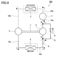
- a refrigeration cycle apparatus 500 shown in Fig. 9 is conventionally known as a refrigeration cycle apparatus provided with an expander that recovers power by expanding a working fluid, and a second compressor that preliminarily increases the pressure of the working fluid (for example, see JP 2003-307358 A ). With reference to Fig. 9 , the configuration of the conventional refrigeration cycle apparatus 500 is described.
- the refrigeration cycle apparatus 500 is provided with a working fluid circuit 6 formed of a first compressor 1, a heat radiator 2, an expander 3, an evaporator 4, a second compressor 5, and flow passages 10a to 10e connecting these components in this order.
- the second compressor 5 is coupled to the expander 3 by a power-recovery shaft 7, and is driven by receiving mechanical energy recovered by the expander 3, via the power-recovery shaft 7.
- bypass passage 8 that bypasses the second compressor 5, and a bypass valve 9 that controls the flow of the working fluid in the bypass passage 8 are provided therein.
- the upstream end of the bypass passage 8 is connected to the flow passage 10d connecting the outlet of the evaporator 4 and the suction port of the second compressor 5.
- the downstream end of the bypass passage 8 is connected to the flow passage 10e connecting the discharge port of the second compressor 5 and the suction port of the first compressor 1.
- the refrigeration cycle apparatus 500 is activated according to the following procedures. First, the first compressor 1 starts operating, and the bypass valve 9 is opened. This allows the working fluid in the evaporator 4 to be drawn into the first compressor 1 through the bypass passage 8 as shown by solid arrows in Fig. 9 . The working fluid with the pressure increased in the first compressor 1 is discharged therefrom, thereby causing an increase in the pressure at the suction port of the expander 3. As a result of this, a pressure difference is caused between before and after the expander 3, as shown in Fig. 10 , so that the expander 3 and the second compressor 5 can be activated rapidly. After the expander 3 and the second compressor 5 are activated, the bypass valve 9 is closed. The working fluid flowing out of the evaporator 4 is drawn into the second compressor 5 through the flow passage 10d, as shown by dashed arrows in Fig. 9 . In this way, a smooth transfer to regular operation can be achieved by providing the bypass passage 8.
- Patent Literature 1 JP 2003-307358 A
- the second compressor 5 acts as a load at the time of activation of the expander 3. That is, friction or the like between the power-recovery shaft 7 and the component parts of the second compressor 5 acts as a driving resistance in the expander 3.
- the second compressor 5 and the expander 3 are coupled to each other by the power-recovery shaft 7 that is commonly shared therebetween and thus have identical rotation rates, as well as forming the working fluid circuit 6 of a single channel. Accordingly, the volume of the second compressor 5 and the volume of the expander 3 need to be set so that the mass of the working fluid to be drawn by the second compressor 5 per unit time is equal to the mass of the working fluid to be drawn by the expander 3 per unit time.
- Fig. 11 is a Mollier diagram when carbon dioxide is used as the working fluid in the conventional refrigeration cycle apparatus 500.
- the working fluid drawn by the second compressor 5 has a pressure of 40 kg/cm 2 and a temperature of about 10°C (point A in Fig. 11 ). At this time, the working fluid has a density of 108.0 kg/m 3 .
- the working fluid drawn by the expander 3 has a pressure of 100 kg/cm 2 and a temperature of 40°C (point C in Fig. 11 ). At this time, the working fluid has a density of 628.61 kg/m 3 .
- the suction volume (m 3 ) of the second compressor 5 is referred to as Vc
- the suction volume (m 3 ) of the expander 3 is referred to as Ve
- the rotation rate (S -1 ) of the power-recovery shaft 7 per second is referred to as N.
- the mass (kg/s) of the working fluid that the second compressor 5 can draw per second and the mass (kg/s) of the working fluid that the expander 3 can draw per second can be expressed respectively by Formula 1 and Formula 2.
- the mass of the working fluid that the second compressor 5 can draw per second 108.0 ⁇ Vc ⁇ N
- the mass of the working fluid that the expander 3 can draw per second 628.61 ⁇ Ve ⁇ N
- the suction volume Vc of the second compressor 5 can be expressed by Formula 3 from the above-mentioned Formula 1 and Formula 2.
- Vc 628.61 / 108.0 ⁇ Ve ⁇ 5.8 ⁇ Ve
- the expander 3 needs to drive the second compressor 5 having a suction volume that is about 5.8 times that of the expander 3, at the time of activation of the refrigeration cycle apparatus 500. Further, the larger the ratio between the density of the working fluid to be drawn by the second compressor 5 and the density of the working fluid to be drawn by the expander 3, the larger the ratio between the suction volume of the second compressor 5 and the suction volume of the expander 3 also should be. In other words, the suction volume of the expander 3 becomes smaller with respect to the suction volume of the second compressor 5, and the driving resistance of the expander 3 at the time of activation of the second compressor 5 relatively increases.
- the present invention aims to solve the above-mentioned conventional problems, and it is an object of the present invention to provide a refrigeration cycle apparatus that can be activated surely and stably.
- the present invention provide a refrigeration cycle apparatus including: a working fluid circuit formed of a first compressor for compressing a working fluid, a heat radiator for cooling the working fluid compressed by the first compressor, an expander for expanding the working fluid cooled by the heat radiator and recovering power from the working fluid, an evaporator for evaporating the working fluid that has been expanded by the expander, a second compressor for increasing the pressure of the working fluid that has been evaporated by the evaporator and supplying it to the first compressor, and flow passages connecting these components in this order; a power-recovery shaft coupling the expander to the second compressor so that the second compressor is driven by the power that has been recovered by the expander; a first bypass passage for communicating between a portion from the discharge port of the first compressor to the suction port of the expander in the working fluid circuit and a portion from the outlet of the evaporator to the suction port of the second compressor in the working fluid circuit; and a first bypass valve, provided on the first bypass passage, for controlling the flow of the working fluid in
- a working fluid at high pressure that is equivalent to one supplied to the suction port of the expander can be supplied to the suction port of the second compressor at the time of activation.
- the pressure at the discharge port of the second compressor is equalized with that at the suction port of the first compressor, that is, the pressure becomes relatively low. In other words, a large pressure difference can be caused between before and after the second compressor. Therefore, the refrigeration cycle apparatus of the present invention can be activated surely and stably independent of operational conditions.
- Fig. 1 is a configuration diagram showing a refrigeration cycle apparatus 100 in Embodiment 1 of the present invention.
- the refrigeration cycle apparatus 100 is provided with a working fluid circuit 106 formed by sequentially connecting a first compressor 101, a heat radiator 102, an expander 103, an evaporator 104 and a second compressor 105, with flow passages (pipes) 106a to 106e.
- a working fluid a refrigerant such as carbon dioxide can be used.
- the first compressor 101 is constituted by arranging a compression mechanism 101a and a motor 101b for driving the compression mechanism 101a in a single closed casing 101c holding lubrication oil.
- the first compressor 101 compresses the working fluid to high temperature and high pressure.
- a scroll compressor or a rotary compressor, for example, can be used as the first compressor 101.
- the discharge port of the first compressor 101 is connected to the inlet of the heat radiator 102 via the flow passage 106a.
- the heat radiator 102 allows the working fluid that has been compressed to high temperature and high pressure by the first compressor 101 to radiate heat. (The heat radiator 102 cools the working fluid that has been compressed to high temperature and high pressure by the first compressor 101.)
- the outlet of the heat radiator 102 is connected to the suction port of the expander 103 via the flow passage 106b.
- the expander 103 expands the working fluid that has flowed out of the heat radiator 102 and is at intermediate temperature and high pressure.
- the expander 103 converts the expansion energy (power) of the working fluid into mechanical energy so as to recover it.
- the discharge port of the expander 103 is connected to the inlet of the evaporator 104 via the flow passage 106c.
- a scroll expander or a rotary expander, for example, can be used as the expander 103.
- a fluid pressure motor expander can be used as the expander 103.
- the fluid pressure motor expander is a fluid machine that recovers power from a working fluid by sequentially performing processes of drawing the working fluid from the heat radiator 102 and discharging the drawn working fluid into the evaporator 104 without performing any substantial expansion process in the working chamber.
- the detailed structure and the operational principle of the fluid pressure motor expander is disclosed, for example, in WO 2008/050654 A .
- the evaporator 104 evaporates the working fluid at low temperature and low pressure that has been expanded by the expander 103, by heating.
- the outlet of the evaporator 104 is connected to the suction port of the second compressor 105 via the flow passage 106d.
- the second compressor 105 draws the working fluid that has flowed out of the evaporator 104 and is at intermediate temperature and low pressure.
- the second compressor 105 discharges it into the first compressor 101 after preliminarily increasing the pressure thereof.
- the discharge port of the second compressor 105 is connected to the suction port of the first compressor 101 via the flow passage 106e.
- a scroll compressor or a rotary compressor can be used as the second compressor 105.
- a fluid pressure motor compressor can be used as the second compressor 105.
- the fluid pressure motor compressor is a fluid machine that increases the pressure of a working fluid by substantially sequentially performing processes of drawing the working fluid from the evaporator 104 and discharging the drawn working fluid into the first compressor 101.
- the fluid pressure motor compressor is a fluid machine that allows substantially no volume change of the working fluid in a working chamber.
- the fluid pressure motor compressor has basically the same structure as the fluid pressure motor expander, and the above-mentioned literature discloses it in detail.
- the expander 103 and the second compressor 105 are accommodated in a single closed casing 109 holding lubrication oil.
- the expander 103 is coupled to the second compressor 105 by a power-recovery shaft 107.
- the expander 103, the second compressor 105 and the power-recovery shaft 107 function as a power recovery system 108 that drives the second compressor 105 by transferring the mechanical energy (power) recovered by the expander 103 to the second compressor 105 via the power-recovery shaft 107.
- the second compressor 105 has a larger volume than the expander 103.
- the ratio (Vc/Ve) of the volume Vc of the second compressor 105 with respect to the volume Ve of the expander 103 is set, for example, to the range of 5 to 15. Particularly, in the case of using a working fluid, such as carbon dioxide, that forms a refrigeration cycle with a large pressure difference, the ratio (Vc/Ve) also tends to be large. Generally, the larger the ratio (Vc/Ve), the larger the driving force (torque) is required for the self-activation of the power recovery system 108.
- the volume of the second compressor 105" means a confined volume, that is, the volume of the working chamber at the completion of the drawing process. This should be applied to the volume of the expander 103 as well.
- the refrigeration cycle apparatus 100 is further provided with a first bypass passage 112 and a first bypass valve 113.
- the first bypass passage 112 is connected to the working fluid circuit 106 so as to communicate between the flow passage 106b connecting the outlet of the heat radiator 102 to the suction port of the expander 103, and the flow passage 106d connecting the outlet of the evaporator 104 to the suction port of the second compressor 105.
- the first bypass valve 113 is provided on the first bypass passage 112, and controls the flow of the working fluid in the first bypass passage 112.
- the upstream end K1 of the first bypass passage 112 is connected to the flow passage 106b, and the downstream end K2 of the first bypass passage 112 is connected to the flow passage 106d. That is, the first bypass passage 112 is a flow passage that allows the working fluid in the flow passage 106b to be drawn directly into the second compressor 105, before the power-recovery shaft 107 is rotated, while bypassing the expander 103 and the evaporator 104.
- the position of the upstream end K1 is not limited to the position shown in Fig. 1 . That is, the position of the upstream end K1 of the first bypass passage 112 is not specifically limited, as long as a portion from the discharge port of the first compressor 101 to the suction port of the expander 103 in the working fluid circuit 106 and a portion from the outlet of the evaporator 104 to the suction port of the second compressor 105 in the working fluid circuit 106 can be communicated with each other.
- the first bypass passage 112 may be connected to the working fluid circuit 106 in such a way as to communicate between the flow passage 106a connecting the discharge port of the first compressor 101 to the inlet of the heat radiator 102, and the flow passage 106d connecting the outlet of the evaporator 104 to the suction port of the second compressor 105.
- the first bypass passage 112 may be branched from the heat radiator 102.
- the heat radiator 102 is composed of an upstream part and a downstream part, the first bypass passage 112 can be easily branched from a portion between these two parts.
- the first bypass valve 113 is provided in the upstream end section of the first bypass passage 112.
- the "upstream end section” corresponds to a section defined between the upstream end K1 and the point of L 1 /4 from the upstream end K1 toward the downstream end K2, when the full length of the first bypass passage 112 is referred to as L 1 .
- the position of the first bypass valve 113 is not specifically limited, and may be provided in the downstream end section of the first bypass passage 112, for example.
- the "downstream end section” corresponds to a section defined between the downstream end K2 and the point of L 1 /4 from the downstream end K2 toward the upstream end K1.
- the first bypass valve 113 used in Embodiment 1 is an on-off valve, though it is not limited thereto.
- a three-way valve can be used as the first bypass valve 113.
- the use of a three-way valve is advantageous in that the number of pipe connections can be reduced.
- the refrigeration cycle apparatus 100 is further provided with an activation assist valve 114 provided on the working fluid circuit 106 at a point that is located between the outlet of the evaporator 104 and the suction port of the second compressor 105, and that is closer to the evaporator 104 than the downstream end K2 of the first bypass passage 112 is.
- the activation assist valve 114 controls the flow of the working fluid in the flow passage 106d.
- An on-off valve can be used as the activation assist valve 114.
- the working fluid in the flow passage 106b is allowed to flow directly into the suction port of the second compressor 105 through the first bypass passage 112. At that time, the working fluid can be prevented from flowing, from the evaporator 104 into the second compressor 105, by closing the activation assist valve 114.
- the refrigeration cycle apparatus 100 is further provided with a second bypass passage 110 and a second bypass valve 111.
- the second bypass passage 110 is connected to the working fluid circuit 106 so as to communicate between the flow passage 106c connecting the discharge port of the expander 103 to the inlet of the evaporator 104, and the flow passage 106e connecting the discharge port of the second compressor 105 to the suction port of the first compressor 101. That is, the second bypass passage 110 bypasses the evaporator 104 and the second compressor 105.
- the second bypass valve 111 is provided on the second bypass passage 110, and controls the flow of the working fluid in the second bypass passage 110.
- the upstream end H1 of the second bypass passage 110 is connected to the flow passage 106c, and the downstream end H2 of the second bypass passage 110 is connected to the flow passage 106e. That is, the second bypass passage 110 is a flow passage that allows the working fluid in the flow passage 106c to be drawn directly into the first compressor 101, while bypassing the evaporator 104 and the second compressor 105.
- the position of the upstream end H1 is not limited to the position shown in Fig. 1 .
- the upstream end H1 may be positioned at any point in the zone from the discharge port of the expander 103 to the downstream end K2 of the first bypass passage 112.
- the second bypass passage 110 may be connected to the working fluid circuit 106 in such a way as to communicate between a portion from the outlet of the evaporator 104 to the downstream end K2 of the first bypass passage 112 in the working fluid circuit 106 (a part of the flow passage 106d), and a portion from the discharge port of the second compressor 105 to the suction port of the first compressor 101 in the working fluid circuit 106 (flow passage 106e).
- the second bypass passage 110 may be branched from the evaporator 104.
- the second bypass passage 110 can be easily branched from a portion between these two parts.
- the second bypass valve 111 is provided in the upstream end section of the second bypass passage 110.
- the "upstream end section” corresponds to a section defined between the upstream end H1 and the point of L 2 /4 from the upstream end H1 toward the downstream end H2, when the full length of the second bypass passage 111 is referred to as L 2 .
- the second bypass valve 111 may be provided also in the downstream end section of the second bypass passage 111.
- the "downstream end section” corresponds to a section defined between the downstream end H2 and the point of L 2 /4 from the downstream end H2 toward the upstream end H1.
- the second bypass valve 111 used in Embodiment 1 is a check valve, it is not limited thereto. An on-off valve or a three-way valve may be used therefor.
- the second bypass valve 111 allows the working fluid in the flow passage 106c to flow into the second bypass passage 110. That is, when the pressure in the flow passage 106e is lower than the pressure in the flow passages between the discharge port of the expander 103 and the suction port of the second compressor 105 (the flow passage 106c, the evaporator 104 and the flow passage 106d), the working fluid in the flow passage 106c is allowed to flow directly into the suction port of the first compressor 101 through the second bypass passage 110.
- the refrigeration cycle apparatus 100 is further provided with a controller 117 for controlling opening and closing of the first bypass valve 113 and the activation assist valve 114.
- the first bypass valve 113 and the activation assist valve 114 are provided respectively with valve opening and closing devices 115 and 116.
- the valve opening and closing devices 115 and 116 typically are composed of an actuator for actuating valves such as a solenoid, and are controlled by the controller 117.
- the controller 117 typically is composed of a microcomputer.
- An input apparatus 118 provided with an activation button is connected to the controller 117. Upon input of an operation command to the controller 117 through the input apparatus 118, a specific control program stored in the internal memory of the controller 117 is executed.
- an activation command (activation signal) is transmitted from the input apparatus 118 to the controller 117.
- the controller 117 performs a specific activation control to be described later with reference to Fig. 2 . Further, the controller 117 controls the operation of the motor 101b that drives the first compressor 101.
- the refrigeration cycle apparatus 100 is further provided with an activation detector 119 for detecting that the second compressor 105 has been activated.
- the activation detector 119 transmits the detection signal to the controller 117.
- the controller 117 detects the activation of the second compressor 105 on the basis of the acquisition of the detection signal.
- a temperature detector, a pressure detector, or the like can be used as the activation detector 119.
- the temperature detector when used as the activation detector 119 for example, includes a temperature detecting element such as a thermocouple and a thermistor, and detects the difference ⁇ T between the temperature of the working fluid to be drawn into the expander 103 and the temperature of the working fluid discharged from the expander 103.
- the pressure detector when used as the activation detector 119 includes a piezoelectric element, and detects the difference ⁇ P between the pressure of the working fluid to be drawn into the expander 103 and the pressure of the working fluid discharged from the expander 103.
- a timer for measuring the time elapsed from the time point of the activation of the first compressor 101 may be provided as the activation detector 119 for detecting the activation of the second compressor 105.
- a timer can be provided also as a function of the controller 117.
- the controller 117 itself can serve as the activation detector 119.
- a contact or noncontact displacement sensor for detecting the driving of the power-recovery shaft 107 such as an encoder, may be provided as the activation detector 119 for detecting the activation of the second compressor 105.
- the method for detecting that "the second compressor 105 has been activated" differs as follows.
- a specific value T 1 that has been experimentally or theoretically determined is set by the controller 117.
- the controller 117 detects that "the second compressor 105 has been activated" when the temperature difference ⁇ T detected by the temperature detector exceeds the specific value T 1 .
- a specific value P 1 that has been experimentally or theoretically determined is set by the controller 117.
- the controller 117 detects that "the second compressor 105 has been activated" when the pressure difference ⁇ P detected by the pressure detector exceeds the specific value P 1 .
- the activation of the second compressor 105 can be detected from the comparison between the temperature difference ⁇ T and the specific value T 1 , or from the comparison between the pressure difference ⁇ P and the specific value P 1 .
- the first compressor 101 When the first compressor 101 is activated, the working fluid discharged from the first compressor 101 is supplied to the suction port of the second compressor 105 through the first bypass passage 112. This activates the power recovery system 108.
- the second compressor 105 serves as a driving source, and therefore the power recovery system 108 starts rotating before a large temperature difference is made between the suction temperature of the first compressor 101 and the discharge temperature of the first compressor 101.
- the rotation rate of the power recovery system 108 also is low.
- the rotation rate of the expander 103 also is low. This state corresponds to the "narrow state" in terms of the expansion valve. Accordingly, the discharge temperature and the discharge pressure of the first compressor 101 gradually increase as well.
- the power to rotate the expander 103 and the second compressor 105 also increases, so that the rotation rate of the power recovery system 108 becomes high. Then, once a high rotation rate is achieved, the power recovery system 108 stably rotates under the influence of the inertial force. It is desirable that the first bypass passage 112 is kept open until such a stable rotation state is achieved.
- the suction temperature of the expander 103 gradually increases from substantially the same temperature as the outdoor air temperature at the stopped state.
- the suction temperature of the expander 103 and the discharge temperature of the expander 103 each gradually increase, as mentioned above.
- the difference between the suction temperature and the discharge temperature also gradually grows. This also can be applied to the pressure. Therefore, it is possible to detect the activation of the second compressor 105 (the activation of the power recovery system 108) by setting appropriate values as the specific values T 1 and P 1 (for example, slightly larger values than the temperature difference and the pressure difference at the time of activation).
- the second compressor 105 It also is possible to detect the activation of the second compressor 105 on the basis of the discharge temperature of the expander 103 or the discharge pressure of the expander 103, instead of the temperature difference ⁇ and the pressure difference ⁇ T.
- the expander 103 When the power recovery system 108 is activated, the expander 103 also rotates. After drawing the working fluid, the expander 103 expands the drawn working fluid and discharges it. Therefore, the working fluid discharged from the expander 103 has lower temperature and pressure than before being drawn thereinto. It is possible to determine that the second compressor 105 has been activated, by capturing a sudden change in the temperature (or pressure) as well as monitoring the temperature (or pressure) at the discharge port of the expander 103 in chronological terms.
- a specific time t that has been experimentally or theoretically determined is set by the controller 117.
- the controller 117 transmits a control signal to the motor 101b of the first compressor 101 and starts measuring the time by the timer.
- the controller 117 detects that "the second compressor 105 has been activated" when the time measured by the timer exceeds the specific time t.
- the "specific time t" is written in the activation control program to be executed in the controller 117.
- the time from the time point of the activation of the first compressor 101 to the activation of the second compressor 105 is actually measured under various operational conditions (such as outdoor air temperature). Then, the time from which the activation of the second compressor 105 is determinable in all the operational conditions can be set as the "specific time t".
- a model of the refrigeration cycle apparatus 100 is constructed, and a pressure difference that is necessary and sufficient to activate the power recovery system 108 is estimated by computer simulation. Then, using parameters such as the volume of the first compressor 101 and the filling amount of the working fluid in the working fluid circuit 106, the initial activation time necessary to produce the estimated pressure difference is calculated. The calculated initial activation time can be set as the "specific time t".
- Fig. 2 is a flow chart of the activation control of the refrigeration cycle apparatus 100.
- the refrigeration cycle apparatus 100 starts the regular operation after performing the activation control shown in Fig. 2 .
- the first compressor 101 is stopped, the first bypass valve 113 is closed, and the activation assist valve 114 is opened.
- the pressure of the working fluid in the working fluid circuit 106 is substantially uniform.
- a fan or a pump for causing a fluid (air or water) that should exchange heat with the working fluid to flow into the heat radiator 102 is actuated after the completion of the activation control.
- a fan or a pump for causing a fluid that should exchange heat with the working fluid to flow into the evaporator 104 also is actuated after the completion of the activation control.
- step S11 in response to the reception of the activation command from the input apparatus 118, the controller 117 transmits a control signal to the valve opening and closing devices 115 and 116 so that the first bypass valve 113 is opened and the activation assist valve 114 is closed (step S12). This allows the first bypass passage 112 to be opened, and the flow passage 106d to be closed between the outlet of the evaporator 104 and the downstream end K2 of the first bypass passage 112.
- the controller 117 starts supplying power to the motor 101b so that the first compressor 101 is activated (step S13).
- This allows the working fluid in the flow passage 106e and the second bypass passage 110 to be drawn into the first compressor 101.
- the activation assist valve 114 may be closed. That is, there is no problem as long as the working fluid is allowed to flow in the first bypass passage 112 after the activation of the first compressor 101 and before the rotation of the power-recovery shaft 107.
- the pressure in the flow passage 106e and the second bypass passage 110 decreases.
- the working fluid that has flown into the second bypass passage 110 is drawn into the first compressor 101 to be compressed therein, and discharged into the flow passage 106a. Accordingly, the pressure in the flow passages from the discharge port of the expander 103 to the activation assist valve 114 (the flow passage 106c, the evaporator 104 and a part of the flow passage 106d) decreases.
- the pressure in the flow passages from the discharge port of the first compressor 101 to the suction port of the expander 103 increases.
- the compressed working fluid flows also into the flow passage 106d between the activation assist valve 114 and the suction port of the second compressor 105 through the first bypass passage 112. This causes the pressure in the flow passage from the activation assist valve 114 to the suction port of the second compressor 105 (a part of the flow passage 106d) to increase.
- the pressure at the suction port of each of the expander 103 and the second compressor 105 is rendered relatively high, and the pressure at the discharge port of each of the expander 103 and the second compressor 105 is rendered relatively low. That is, a pressure difference can be caused not only between the suction port and the discharge port of the expander 103, but also between the suction port and the discharge port of the second compressor 105.
- the pressure difference of the working fluid acts on each of the expander 103 and the second compressor 105, and thus self-activation of the power recovery system 108 can be easily achieved.
- the controller 117 Upon detecting the activation of the second compressor 105 through the activation detector 119 (step S14), the controller 117 transmits a control signal to the valve opening and closing devices 115 and 116 so that the first bypass valve 113 is closed and the activation assist valve 114 is opened (step S15). Specifically, the controller 117 detects the activation of the second compressor 105 by receiving the detection signal from the activation detector 119, and thereafter closes the first bypass valve 113 and opens the activation assist valve 114. This allows the first bypass passage 112 to be closed, and the flow passage 106d to be opened. After the completion of the activation control, the refrigeration cycle apparatus 100 is transferred to the regular operation in which the working fluid is circulated in the working fluid circuit 106.
- the second bypass valve 111 serving as a check valve is closed.
- the pressure in the flow passage 106e and the second bypass passage 110 on the downstream side of the second bypass valve 111 is higher than the pressure in the flow passage 106c, the evaporator 104 and the flow passage 106d, and thus the second bypass valve 111 is kept closed. This allows the working fluid to be circulated in the working fluid circuit 106 during the regular operation.
- the working fluid in the liquid phase might be drawn into the second compressor 105 at the time of activation of the refrigeration cycle apparatus 100, though it depends also on the conditions such as outdoor air temperature. Therefore, the fluid pressure motor compressor described above can be used suitably as the second compressor 105. This is because the fluid pressure motor compressor allows substantially no volume change of the working fluid to be caused in the working chamber and therefore is capable of accepting the working fluid in a liquid phase to be drawn therein to some extent.
- a pressure pulsation might occur in the flow passage 106e on the basis that the working fluid is confined in the compression mechanism 101a.
- a part of the second bypass passage 110 (the part from the second bypass valve 111 to the downstream end H2) can function as a buffer space to allow the volume of the flow passage 106e to extend. Therefore, the pulse width of the pressure pulsation that has occurred in the flow passage 106e can be expected to be reduced, resulting in an enhancement in the operational reliability of the refrigeration cycle apparatus 100.
- a pressure pulsation might occur in the flow passage 106d on the basis that the working fluid is confined in the working chamber of the second compressor 105.
- a part of the first bypass passage 112 (the part from the first bypass valve 113 to the downstream end K2) can function as a buffer space to allow the volume of the flow passage 106d to extend. Therefore, the pulse width of the pressure pulsation that has occurred in the flow passage 106d can be expected to be reduced, resulting in an enhancement in the operational reliability of the refrigeration cycle apparatus 100.
- the rotation rate of the first compressor 101 is progressively reduced, for example.
- the working fluid travels through the first compressor 101, the expander 103 and the second compressor 105, taking sufficient time. Therefore, the pressure difference in the working fluid circuit 106 naturally disappears, so that the pressure becomes substantially uniform to be stabilized. This allows the expander 103 and the second compressor 105 to be stopped naturally.
- the first bypass valve 113 is opened, and the activation assist valve 114 is closed, according to Embodiment 1. Therefore, the working fluid in the flow passages from the discharge port of the first compressor 101 to the suction port of the expander 103 can be supplied to the suction port of the second compressor 105 through the first bypass passage 112. This causes the pressure at the suction port of the second compressor 105 to increase. Further, the working fluid in the flow passages from the discharge port of the expander 103 to the activation assist valve 114 can be supplied directly to the first compressor 101 through the second bypass passage 110 in addition to the working fluid in the flow passage 106e.
- the pressure in the flow passage 106e and the second bypass passage 110 on the downstream side of the second bypass valve 111 decreases. This allows the second bypass valve 111 serving as a check valve to be opened.
- the working fluid in the flow passages from the discharge port of the expander 103 to the activation assist valve 114 flows into the second bypass passage 110, and is drawn into the first compressor 101 together with the working fluid in the second bypass passage 110 and the flow passage 106e.
- a pressure difference can be caused not only between the suction port and the discharge port of the expander 103 but also between the suction port and the discharge port of the second compressor 105. Therefore, the power recovery system 108 can be activated stably and surely, resulting in an improvement in the reliability of the refrigeration cycle apparatus 100.
- Fig. 3 is a configuration diagram of a refrigeration cycle apparatus 200 in Embodiment 2 of the present invention.
- the refrigeration cycle apparatus 200 differs from Embodiment 1 in that a three-way valve is used as the first bypass valve 201. That is, the first bypass valve 201 functions both as the first bypass valve 113 and the activation assist valve 114 in Embodiment 1.
- Embodiment 2 common parts with Embodiment 1 are designated with identical reference numerals, and the detailed description thereof is omitted.
- the first bypass valve 201 is provided at the junction of the downstream end K2 of the first bypass passage 112 and the flow passage 106d. This makes it possible to open and close the first bypass passage 112 and to open and close the flow passage 106d with one valve, easily and conveniently.
- the channel for the working fluid can be switched easily and conveniently between (a) the state where the flow passage 106d is opened, and the first bypass passage 112 is closed (for example, in the regular operation), and (b) the state where the first bypass passage 112 is opened, and the flow passage 106d is closed at the junction with the downstream end K2 of the first bypass passage 112 (for example, in the activation control).
- the first bypass valve 201 may be provided at the junction of the upstream end K1 of the first bypass passage 112 and the flow passage 106b.
- a valve switching device 202 is provided in the first bypass valve 201.
- the valve switching device 202 is typically composed of an actuator such as a solenoid, and controlled by the controller 117.
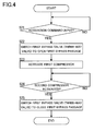
- Fig. 4 is a flow chart of the activation control of the refrigeration cycle apparatus 200.
- the refrigeration cycle apparatus 200 starts the regular operation after performing the activation control shown in Fig. 4 .
- the first compressor 101 is stopped, the flow passage 106d is opened by the first bypass valve 201, and the first bypass passage 112 is closed (the above state (a)).
- the pressure of the working fluid in the working fluid circuit 106 is substantially uniform.
- step S21 in response to the reception of the activation command from the input apparatus 118, the controller 117 transmits a control signal to a valve control device 202 so that the state is switched from the above-described state (a) to the state (b) (step S22).
- step S23 the controller 117 starts supplying power to the motor 101b so that the first compressor 101 is activated. This allows the working fluid in the flow passage 106e and the second bypass passage 110 to be drawn into the first compressor 101.
- the process of step S22 may be carried out in response to the activation of the first compressor 101.
- the pressure in the flow passage 106e and the second bypass passage 110 decreases.
- the working fluid that has flown into the second bypass passage 110 is drawn into the first compressor 101 to be compressed therein, and discharged into the flow passage 106a. Accordingly, the pressure in the flow passages from the discharge port of the expander 103 to the first bypass valve 201 (the flow passage 106c, the evaporator 104, a part of the flow passage 106d) also decreases.
- the pressure in the flow passages from the discharge port of the first compressor 101 to the suction port of the expander 103 increases.
- the compressed working fluid flows also into the flow passage 106d between the first bypass valve 201 and the suction port of the second compressor 105 through the first bypass passage 112.
- This causes the pressure in the flow passage from the first bypass valve 201 to the suction port of the second compressor 105 (a part of the flow passage 106d) to increase.
- the state shown in Fig. 6A is established, and thus self-activation of the power recovery system 108 can be easily achieved.
- step S24 Upon detecting the activation of the second compressor 105 through the activation detector 119 (step S24), the controller 117 transmits a control signal to the valve switching device 202 so that the state is switched from the above-described state (b) to the state (a) (step S25). This causes the first bypass valve 201 to be switched, and the first bypass passage 112 to be closed. After the completion of the activation control, the refrigeration cycle apparatus 200 is transferred to the regular operation.
- a part of the second bypass passage 110 (the part from the second bypass valve 111 to the downstream end H2) can function as a buffer space to allow the volume of the flow passage 106e to extend. Accordingly, as has been described in Embodiment 1, the pulse width of the pressure pulsation that has occurred in the flow passage 106e can be expected to be reduced, resulting in an enhancement in the operational reliability of the refrigeration cycle apparatus 200.
- the first bypass passage 112 can function as a buffer space to allow the volume of the flow passage 106b to extend. Accordingly, the pulse width of the pressure pulsation that has occurred in the flow passage 106b can be expected to be reduced, resulting in an enhancement in the operational reliability of the refrigeration cycle apparatus 200.
- the first bypass passage 112 is opened, and the flow passage 106d is closed at the junction with the downstream end K2 of the first bypass passage 112, according to Embodiment 2. Therefore, the working fluid in the flow passages from the discharge port of the first compressor 101 to the suction port of the expander 103 can be supplied to the suction port of the second compressor 105 through the first bypass passage 112. This causes the pressure at the suction port of the second compressor 105 to increase. Further, the working fluid in the flow passages from the discharge port of the expander 103 to the first bypass valve 201 can be supplied directly to the first compressor 101 through the second bypass passage 110 in addition to the working fluid in the flow passage 106e.
- the pressure in the flow passage 106e and the second bypass passage 110 on the downstream side of the second bypass valve 111 decreases. This allows the second bypass valve 111 serving as a check valve to be opened.
- the working fluid in the flow passages from the discharge port of the expander 103 to the first bypass valve 201 flows into the second bypass passage 110, and is drawn into the first compressor 101 together with the working fluid in the second bypass passage 110 and the flow passage 106e.
- the pressure loss of the working fluid due to the evaporator 104 and the second compressor 105 can be avoided, and the pressure decrease of the working fluid to be drawn by the first compressor 101 can be suppressed, at the time of activation. These allow a reduction in the power required to increase the pressure of the working fluid by the first compressor 101.
- a pressure difference can be caused not only between the suction port and the discharge port of the expander 103 but also between the suction port and the discharge port of the second compressor 105. Therefore, the power recovery system 108 can be activated stably and surely, resulting in an improvement in the reliability of the refrigeration cycle apparatus 200.
- Embodiments 1 and 2 are provided with the second bypass passage 110 and the second bypass valve 111. However, these are not always necessary. That is, a refrigeration cycle apparatus 300 with a configuration in which the second bypass passage 110 and the second bypass valve 111 are omitted can be proposed, as shown in Fig. 5 .
- the first bypass valve 113 is opened, and the activation assist valve 114 is closed, at the time of activation.
- the first compressor 101 can draw only the working fluid in the flow passage 106e. That is, focusing on the amount of the working fluid that the first compressor 101 can draw thereinto, Embodiment 3 may be less advantageous than Embodiments 1 and 2.
- a pressure difference can be caused not only between the suction port and the discharge port of the expander 103 but also between the suction port and the discharge port of the second compressor 105 (see Fig. 6A ). Accordingly, even if the second bypass passage 110 and the second bypass valve 111 are omitted, the power recovery system 108 can be activated easily and surely.
- the activation assist valve 114 in the refrigeration cycle apparatus 300.
- a pressure difference is caused only between the suction port and the discharge port of the second compressor 105, as shown in Fig. 6B .
- the driving resistance of the second compressor 105 is relatively larger than the driving resistance of the expander 103. Accordingly, the state shown in Fig. 6B is more advantageous for the activation of the power recovery system 108 than the state shown in Fig. 10 .
- a refrigeration cycle apparatus 400 shown in Fig. 7 differs from the conventional refrigeration cycle apparatus 500 (see Fig. 9 ) in the position of the upstream end H1 of the bypass passage 110. Specifically, the upstream end H1 of the bypass passage 110 is positioned on the flow passage 106c connecting the discharge port of the expander 103 to the inlet of the evaporator 104. Except that, the refrigeration cycle apparatus 400 has the same configuration including the method for detecting the activation as the refrigeration cycle apparatus 100 that has been described with reference to Fig. 1 , etc.
- the refrigeration cycle apparatus 400 allows the following advantageous effects to be obtained on the basis of the difference in the position of the upstream end H1 of the bypass passage 110. That is, according to the refrigeration cycle apparatus 400, the pressure loss of the working fluid due to the evaporator 104 and the second compressor 105 can be avoided during a constant period before and after the activation, and thereby the pressure decrease of the working fluid to be drawn by the first compressor 101 can be suppressed. These result in a reduction in the power required for the first compressor 101 to increase the pressure of the working fluid, thus making it easy to form a stable operation state more rapidly.
- the working fluid in the liquid phase tends to be retained in a comparatively downstream portion inside the evaporator 4 in the state where the conventional refrigeration cycle apparatus 500 ( Fig. 9 ) is stopped.
- the refrigeration cycle apparatus 500 is activated in the state where the working fluid in the liquid phase is retained inside the evaporator 4, the working fluid in the vapor phase inside the flow passages 10c and 10d, and the working fluid in the vapor phase inside the evaporator 4 proceed in the first compressor 1 or the second compressor 5, while passing through the inside of the evaporator 4. Since the working fluid travels a comparatively long distance, the pressure loss also is comparatively large. Furthermore, there is a possibility that the working fluid in the liquid phase is drawn into the first compressor 101, and there also is a possibility that the working fluid in the liquid phase serves as a resistance and increases the pressure loss.
- the working fluid in the vapor phase flows back in the evaporator 104, and is drawn directly into the first compressor 101 through the bypass passage 110, as shown in Fig. 8 .
- the working fluid in the liquid phase travels inside the evaporator 104 while being vaporized, and is drawn into the first compressor 101 through the bypass passage 110.
- the pressure in the evaporator 104 that is, the suction pressure of the first compressor 101 is maintained substantially constant.
- the working fluid in the liquid phase never serves as a resistance, and the pressure loss of the working fluid in the vapor phase is comparatively low.
- the possibility that the working fluid in the liquid phase is drawn into the first compressor 101 at the time of activation is low, and therefore stable activation can be achieved.
- the refrigeration cycle apparatus 100 and 200 of Embodiments 1 and 2 also are provided with the bypass passage 110, and therefore the above-mentioned effects can be obtained at the time of activation.
- the refrigeration cycle apparatus of the present invention is useful as equipments such as water heaters, air conditioners, dryers, etc.
Landscapes
- Engineering & Computer Science (AREA)
- Physics & Mathematics (AREA)
- Mechanical Engineering (AREA)
- Thermal Sciences (AREA)
- General Engineering & Computer Science (AREA)
- Chemical & Material Sciences (AREA)
- Chemical Kinetics & Catalysis (AREA)
- Applications Or Details Of Rotary Compressors (AREA)
- Compressors, Vaccum Pumps And Other Relevant Systems (AREA)
- Control Of Turbines (AREA)
- Control Of Positive-Displacement Pumps (AREA)
Applications Claiming Priority (2)
| Application Number | Priority Date | Filing Date | Title |
|---|---|---|---|
| JP2008325208 | 2008-12-22 | ||
| PCT/JP2009/007066 WO2010073586A1 (ja) | 2008-12-22 | 2009-12-21 | 冷凍サイクル装置 |
Publications (2)
| Publication Number | Publication Date |
|---|---|
| EP2381190A1 true EP2381190A1 (de) | 2011-10-26 |
| EP2381190A4 EP2381190A4 (de) | 2013-10-02 |
Family
ID=42287235
Family Applications (1)
| Application Number | Title | Priority Date | Filing Date |
|---|---|---|---|
| EP09834397.3A Withdrawn EP2381190A4 (de) | 2008-12-22 | 2009-12-21 | Kältekreislaufvorrichtung |
Country Status (5)
| Country | Link |
|---|---|
| US (1) | US20110247358A1 (de) |
| EP (1) | EP2381190A4 (de) |
| JP (1) | JPWO2010073586A1 (de) |
| CN (1) | CN102257332B (de) |
| WO (1) | WO2010073586A1 (de) |
Cited By (2)
| Publication number | Priority date | Publication date | Assignee | Title |
|---|---|---|---|---|
| EP2620721A3 (de) * | 2012-01-30 | 2013-12-18 | LG Electronics, Inc. | Vorrichtung und Verfahren zum Steuern eines Kompressors und Kühlschrank damit |
| EP2765369A4 (de) * | 2011-09-01 | 2015-04-22 | Mitsubishi Electric Corp | Kältekreislaufvorrichtung |
Families Citing this family (8)
| Publication number | Priority date | Publication date | Assignee | Title |
|---|---|---|---|---|
| KR101955977B1 (ko) * | 2012-01-30 | 2019-03-08 | 엘지전자 주식회사 | 압축기 제어 장치와 방법, 및 이를 포함한 냉장고 |
| JP6197745B2 (ja) * | 2013-07-31 | 2017-09-20 | 株式会社デンソー | 車両用冷凍サイクル装置 |
| JP6276000B2 (ja) * | 2013-11-11 | 2018-02-07 | 株式会社前川製作所 | 膨張機一体型圧縮機及び冷凍機並びに冷凍機の運転方法 |
| US10415857B2 (en) | 2015-05-01 | 2019-09-17 | Mayekawa Mfg. Co., Ltd. | Refrigerator and operation method for refrigerator |
| CN111433549A (zh) | 2017-07-17 | 2020-07-17 | 分形散热器技术有限责任公司 | 多重分形散热器系统及方法 |
| JP7192347B2 (ja) * | 2018-09-21 | 2022-12-20 | 株式会社富士通ゼネラル | 冷凍サイクル装置 |
| JP2022087598A (ja) * | 2020-12-01 | 2022-06-13 | 株式会社前川製作所 | 冷凍機及び冷凍機の予冷時の運転方法 |
| JP2025005169A (ja) * | 2023-06-27 | 2025-01-16 | 株式会社ディスコ | 冷却機構 |
Family Cites Families (18)
| Publication number | Priority date | Publication date | Assignee | Title |
|---|---|---|---|---|
| JP3044736B2 (ja) * | 1990-03-30 | 2000-05-22 | ヤマハ株式会社 | 空調ダクト騒音減衰装置 |
| JPH03286968A (ja) * | 1990-03-31 | 1991-12-17 | Aisin Seiki Co Ltd | 極低温冷凍装置 |
| JP2001141315A (ja) * | 1999-11-10 | 2001-05-25 | Aisin Seiki Co Ltd | 冷凍空調機 |
| JP3953871B2 (ja) | 2002-04-15 | 2007-08-08 | サンデン株式会社 | 冷凍空調装置 |
| JP3897681B2 (ja) * | 2002-10-31 | 2007-03-28 | 松下電器産業株式会社 | 冷凍サイクル装置の高圧冷媒圧力の決定方法 |
| JP2004251558A (ja) * | 2003-02-20 | 2004-09-09 | Matsushita Electric Ind Co Ltd | 冷凍サイクル装置とその制御方法 |
| JP4321095B2 (ja) * | 2003-04-09 | 2009-08-26 | 日立アプライアンス株式会社 | 冷凍サイクル装置 |
| JP2006071257A (ja) * | 2004-08-06 | 2006-03-16 | Daikin Ind Ltd | 冷凍サイクル装置 |
| JP4912308B2 (ja) * | 2005-05-06 | 2012-04-11 | パナソニック株式会社 | 冷凍サイクル装置 |
| US8109116B2 (en) * | 2005-08-26 | 2012-02-07 | Mitsubishi Electric Corporation | Dual compressor air conditioning system with oil level regulation |
| JP2007155277A (ja) * | 2005-12-08 | 2007-06-21 | Valeo Thermal Systems Japan Corp | 冷凍サイクル |
| WO2008050654A1 (en) | 2006-10-25 | 2008-05-02 | Panasonic Corporation | Refrigeration cycle device and fluid machine used for the same |
| WO2008054380A2 (en) * | 2006-10-27 | 2008-05-08 | Carrier Corporation | Economized refrigeration cycle with expander |
| US20100058781A1 (en) * | 2006-12-26 | 2010-03-11 | Alexander Lifson | Refrigerant system with economizer, intercooler and multi-stage compressor |
| WO2008140454A1 (en) * | 2007-05-14 | 2008-11-20 | Carrier Corporation | Refrigerant vapor compression system with flash tank economizer |
| DK2147265T3 (da) * | 2007-05-22 | 2012-07-02 | Als S R L | Køleindretning og fremgangsmåde til recirkulering af kølefluid forbundet dermed |
| EP2476973B9 (de) * | 2009-10-07 | 2019-02-13 | Mitsubishi Electric Corporation | Kältekreislaufvorrichtung |
| WO2011135779A1 (ja) * | 2010-04-30 | 2011-11-03 | パナソニック株式会社 | 流体機械および冷凍サイクル装置 |
-
2009
- 2009-12-21 CN CN200980151528.6A patent/CN102257332B/zh not_active Expired - Fee Related
- 2009-12-21 EP EP09834397.3A patent/EP2381190A4/de not_active Withdrawn
- 2009-12-21 WO PCT/JP2009/007066 patent/WO2010073586A1/ja not_active Ceased
- 2009-12-21 US US13/140,331 patent/US20110247358A1/en not_active Abandoned
- 2009-12-21 JP JP2010543836A patent/JPWO2010073586A1/ja not_active Ceased
Cited By (4)
| Publication number | Priority date | Publication date | Assignee | Title |
|---|---|---|---|---|
| EP2765369A4 (de) * | 2011-09-01 | 2015-04-22 | Mitsubishi Electric Corp | Kältekreislaufvorrichtung |
| US9395105B2 (en) | 2011-09-01 | 2016-07-19 | Mitsubishi Electric Corporation | Refrigeration cycle device |
| EP2620721A3 (de) * | 2012-01-30 | 2013-12-18 | LG Electronics, Inc. | Vorrichtung und Verfahren zum Steuern eines Kompressors und Kühlschrank damit |
| US9366246B2 (en) | 2012-01-30 | 2016-06-14 | Lg Electronics Inc. | Apparatus and method for controlling compressor, and refrigerator having the same |
Also Published As
| Publication number | Publication date |
|---|---|
| JPWO2010073586A1 (ja) | 2012-06-07 |
| CN102257332B (zh) | 2013-08-14 |
| WO2010073586A1 (ja) | 2010-07-01 |
| EP2381190A4 (de) | 2013-10-02 |
| US20110247358A1 (en) | 2011-10-13 |
| CN102257332A (zh) | 2011-11-23 |
Similar Documents
| Publication | Publication Date | Title |
|---|---|---|
| EP2381190A1 (de) | Kältekreislaufvorrichtung | |
| CN102859295B (zh) | 制冷循环装置 | |
| EP2015004B1 (de) | Klimaanlage | |
| EP2312136A1 (de) | Abwärmenutzungssystem | |
| JP4053082B2 (ja) | 冷凍サイクル装置 | |
| US7886550B2 (en) | Refrigerating machine | |
| JP4976970B2 (ja) | 冷凍サイクル装置 | |
| US20120131949A1 (en) | Fluid machine and refrigeration cycle apparatus | |
| JP2005214575A (ja) | 冷凍装置 | |
| JP2007009897A (ja) | 熱サイクル装置および高圧保護装置 | |
| JP3710043B2 (ja) | 空気調和装置 | |
| US9121278B2 (en) | Positive displacement expander and refrigeration cycle apparatus including positive displacement expander | |
| JP2007147274A (ja) | 冷凍装置 | |
| JP2013155992A (ja) | ヒートポンプサイクル装置 | |
| WO2006112157A1 (ja) | 冷凍サイクル装置及びその運転方法 | |
| JP2007101179A5 (de) | ||
| JP2004060989A (ja) | 蒸気圧縮式冷凍機及び膨脹機一体型圧縮機 | |
| JP2008032391A (ja) | 冷凍装置 | |
| JP2007101179A (ja) | 冷凍装置 | |
| EP3098542B1 (de) | Kältekreislaufvorrichtung | |
| JP2006162186A (ja) | 冷凍サイクル装置 | |
| JP3594770B2 (ja) | 冷凍空調装置の冷媒回路 | |
| JP2012102968A (ja) | 冷凍サイクル装置 | |
| JP2002071226A (ja) | 冷凍装置 | |
| JP2011102686A (ja) | 加熱システムにおける制御方法 |
Legal Events
| Date | Code | Title | Description |
|---|---|---|---|
| PUAI | Public reference made under article 153(3) epc to a published international application that has entered the european phase |
Free format text: ORIGINAL CODE: 0009012 |
|
| 17P | Request for examination filed |
Effective date: 20110722 |
|
| AK | Designated contracting states |
Kind code of ref document: A1 Designated state(s): AT BE BG CH CY CZ DE DK EE ES FI FR GB GR HR HU IE IS IT LI LT LU LV MC MK MT NL NO PL PT RO SE SI SK SM TR |
|
| DAX | Request for extension of the european patent (deleted) | ||
| A4 | Supplementary search report drawn up and despatched |
Effective date: 20130903 |
|
| RIC1 | Information provided on ipc code assigned before grant |
Ipc: F25B 1/00 20060101AFI20130828BHEP Ipc: F25B 1/10 20060101ALI20130828BHEP Ipc: F25B 9/00 20060101ALI20130828BHEP |
|
| STAA | Information on the status of an ep patent application or granted ep patent |
Free format text: STATUS: THE APPLICATION HAS BEEN WITHDRAWN |
|
| 18W | Application withdrawn |
Effective date: 20131213 |