EP2381419A2 - Appareil de capture d'images, procédé de détection de suivi d'objet et produit de programme informatique - Google Patents
Appareil de capture d'images, procédé de détection de suivi d'objet et produit de programme informatique Download PDFInfo
- Publication number
- EP2381419A2 EP2381419A2 EP11163205A EP11163205A EP2381419A2 EP 2381419 A2 EP2381419 A2 EP 2381419A2 EP 11163205 A EP11163205 A EP 11163205A EP 11163205 A EP11163205 A EP 11163205A EP 2381419 A2 EP2381419 A2 EP 2381419A2
- Authority
- EP
- European Patent Office
- Prior art keywords
- image
- unit
- moving amount
- capturing apparatus
- image capturing
- Prior art date
- Legal status (The legal status is an assumption and is not a legal conclusion. Google has not performed a legal analysis and makes no representation as to the accuracy of the status listed.)
- Granted
Links
Images




Classifications
-
- G—PHYSICS
- G06—COMPUTING OR CALCULATING; COUNTING
- G06T—IMAGE DATA PROCESSING OR GENERATION, IN GENERAL
- G06T7/00—Image analysis
- G06T7/20—Analysis of motion
- G06T7/246—Analysis of motion using feature-based methods, e.g. the tracking of corners or segments
- G06T7/248—Analysis of motion using feature-based methods, e.g. the tracking of corners or segments involving reference images or patches
-
- H—ELECTRICITY
- H04—ELECTRIC COMMUNICATION TECHNIQUE
- H04N—PICTORIAL COMMUNICATION, e.g. TELEVISION
- H04N23/00—Cameras or camera modules comprising electronic image sensors; Control thereof
- H04N23/60—Control of cameras or camera modules
- H04N23/61—Control of cameras or camera modules based on recognised objects
-
- H—ELECTRICITY
- H04—ELECTRIC COMMUNICATION TECHNIQUE
- H04N—PICTORIAL COMMUNICATION, e.g. TELEVISION
- H04N23/00—Cameras or camera modules comprising electronic image sensors; Control thereof
- H04N23/60—Control of cameras or camera modules
- H04N23/67—Focus control based on electronic image sensor signals
- H04N23/673—Focus control based on electronic image sensor signals based on contrast or high frequency components of image signals, e.g. hill climbing method
-
- G—PHYSICS
- G06—COMPUTING OR CALCULATING; COUNTING
- G06T—IMAGE DATA PROCESSING OR GENERATION, IN GENERAL
- G06T2207/00—Indexing scheme for image analysis or image enhancement
- G06T2207/10—Image acquisition modality
- G06T2207/10024—Color image
Definitions
- the present invention relates to an image capturing apparatus, a method of detecting tracking object, and a computer program product.
- the object tracking function is a function to move a focus area and such in an image capturing range of the image capturing apparatus in response to the movement of a tacking target of a photographic subject to allow focus adjustment, calculation of an exposure condition, and the like to be carried out by following the moving photographic subject.
- Japanese Patent Application Laid-open No. 2009-177503 discloses an image capturing apparatus that sets an object selected by the operation of a user as a tracking target. More specifically, in the image capturing apparatus disclosed in Japanese Patent Application Laid-open No. 2009-177503 , a rectangular frame is superimposed on a view image displayed on a monitor as a moving image. When the user presses a decision button while an object is positioned inside the frame displayed in the view image, the image capturing apparatus sets the object displayed inside the frame as a tracking target object and starts the operation of object tracking.
- the fact that the tracking target object is selected by the operation of the user, the face detection process, the AF operation, and the like makes it difficult to set the object as a tracking target unless the tracking target object is held still when selecting the object.
- an image capturing apparatus having an object tracking function
- the image capturing apparatus including: an image capturing unit that obtains a frame image constituting a moving image made by successively photographing images containing an object; an image signal processing unit that partitions the frame image obtained by the image capturing unit into a plurality of blocks and calculates for each of the blocks thus obtained luminance information, color information, contrast information, and a motion vector quantity from a previous frame; a motion detection unit that detects a movement of the image capturing apparatus itself; a focal length calculating unit that calculates a focal length of the image capturing apparatus corresponding to a zooming operation; a grouping unit that groups the blocks into each of image areas presumed to be the image area of a same object based on the luminance information and the color information calculated by the image signal processing unit; a moving amount calculating unit that calculates a moving amount of an object contained in each of the image areas grouped by the grouping unit based on the motion vector quantity calculated by the image signal processing unit,
- a method of detecting a tracking object executed in an image capturing apparatus having an object tracking function including: obtaining a frame image constituting a moving image made by successively photographing images containing an object; partitioning the frame image obtained into a plurality of blocks, and calculating for each of the blocks thus obtained luminance information, color information, contrast information, and a motion vector quantity from a previous frame; detecting a movement of the image capturing apparatus itself; calculating a focal length of the image capturing apparatus corresponding to a zooming operation; grouping the blocks into each of image areas presumed to be the image area of a same object based on the luminance information and the color information of each of the blocks; calculating a moving amount of an object contained in each of the image areas grouped based on the motion vector quantity of each of the blocks, the movement of the image capturing apparatus itself, and the focal length of the image capturing apparatus; calculating a contrast value of each of the image areas grouped based on the contrast information of each of
- a computer program product including a non-transitory computer-readable medium having computer-readable program codes for tracking an object performed by an image capturing apparatus, the program codes when executed causing computer to execute: obtaining a frame image constituting a moving image made by successively photographing images containing an object; partitioning the frame image obtained into a plurality of blocks, and calculating for each of the blocks thus obtained luminance information, color information, contrast information, and a motion vector quantity from a previous frame; detecting a movement of the image capturing apparatus itself; calculating a focal length of the image capturing apparatus corresponding to a zooming operation; grouping the blocks into each of image areas presumed to be the image area of a same object based on the luminance information and the color information of each of the blocks; calculating a moving amount of an object contained in each of the image areas grouped based on the motion vector quantity of each of the blocks, the movement of the image capturing apparatus itself, and the focal length of the image capturing apparatus; calculating a moving amount of an object contained in each of the
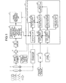
- Fig. 1 is a block diagram illustrating an overall structure of a digital camera according to an embodiment of the invention.
- the digital camera according to the present embodiment is provided with, as depicted in Fig. 1 , an image capturing optical system including a zoom lens 1 and a focusing lens 2, an image capturing section including an image capturing element 3, an amplifier 4, and an A/D converter 5, an image capturing element driving unit (TG) 6, a focus/zoom driving unit 7, an image signal processing unit 8, an image recording/reproducing processing unit 9, a motion detection sensor 10, a band pass filter (BPF) 11, operation members including a zoom button 12, and a control calculating unit (CPU) 13.
- TG image capturing element driving unit
- BPF band pass filter
- CPU control calculating unit
- the zoom lens 1 and the focusing lens 2 of the image capturing optical system are structured to be movable in the optical axis direction thereof by the drive of the focus/zoom driving unit 7.
- the zoom lens 1 and the focusing lens 2 focus incident light on a light receiving surface of the image capturing element 3 as an optical image.
- the zoom lens 1 and the focusing lens 2 move to their appropriate positions to adjust the focal length and the focus position of the digital camera.
- the image capturing element 3 is an image sensor that converts the optical image focused on the light receiving surface to an electrical signal by a photoelectric conversion function to output the signal and, as for the element, a CMOS sensor, a CCD sensor, or the like is used.
- the image capturing element 3 is driven corresponding to a drive timing signal output from the image capturing element driving unit (TG) 6 under the control of the control calculating unit (CPU) 13.
- the electrical signal output from the image capturing element 3 is converted to digital data by the A/D converter 5 after being processed by correlated double sampling and such through which its gain is adjusted by the amplifier 4.
- the image signal processing unit 8 partitions the frame image received from the A/D converter 5 in the shooting stand-by state into a plurality of blocks and calculates for each of the partitioned blocks four kinds of parameters of luminance information, color information, contrast information, and a motion vector quantity from a previous frame and outputs the calculated parameters to the control calculating unit (CPU) 13 as image information.
- the detail of the process by the image signal processing unit 8 will be explained later.
- the image recording/reproducing processing unit 9, under the control of the control calculating unit (CPU) 13, carries out processes such as recording the image data of a still image input to the image signal processing unit 8 from the A/D converter 5 in a recording medium such as a memory card and reproducing the image data of a still image recorded in the recording medium to display the still image on a monitor screen of the digital camera.
- the image recording/reproducing processing unit 9 carries out the process of displaying a moving image for monitoring on the monitor screen of the digital camera based on the image data of the frame image input to the image signal processing unit 8 from the A/D converter 5.
- the motion detection sensor 10 is provided fixed to the housing of the digital camera or inside thereof, and detects two-dimensional movement of the digital camera in the horizontal direction and in the vertical direction.
- the detection value of the motion detection sensor 10 is fed to the control calculating unit (CPU) 13 through the band pass filter (BPF) 11.
- the zoom button 12 is an operation member with which a user operates when conducting a zooming operation of the digital camera.
- the control calculating unit (CPU) 13 activates the focus/zoom driving unit 7 to move the zoom lens 1 in the optical axis direction, thereby adjusting the focal length of the digital camera.
- the control calculating unit (CPU) 13 can calculate the focal length corresponding to the zooming operation of the digital camera in real time based on the operation amount of the zoom button 12.
- the control calculating unit (CPU) 13 comprehensively controls the overall operation of the digital camera based on a control program and control data stored, for example, in a ROM not depicted. More specifically, the control calculating unit (CPU) 13 controls the image capturing element driving unit (TG) 6, the focus/zoom driving unit 7, the amplifier 4, the image recording/reproducing processing unit 9, and the like, so that, in response to an operational instruction and such of the user using various operation members, an image corresponding to the instruction can be appropriately photographed, displayed, or recorded.
- TG image capturing element driving unit
- the amplifier 4 the image recording/reproducing processing unit 9 and the like
- the control calculating unit (CPU) 13 is provided with functional components of a focal length calculating unit 21, a grouping unit 22, a moving amount calculating unit 23, a contrast value calculating unit 24, a tracking object selecting unit 25, an object tracking unit 26, an object position estimating unit 27, and a shutter speed control unit 28. Based on the processes realized by the respective functional components, the control calculating unit (CPU) 13 selects an object of tracking target from the frame image output from the A/D converter 5 in the shooting stand-by state using the four kinds of parameters calculated by the image signal processing unit 8, the detection value of the motion detection sensor 10, and the operation signal of the zoom button 12, and thus carries out an object tracking operation.
- the object tracking function by the digital camera will be described in detail below.
- the object tracking function is executed, for example, by the user selecting an object tracking mode from a plurality of photographing modes provided to the digital camera using the operation member.
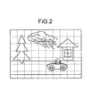
- the image signal processing unit 8 partitions the frame image output from the A/D converter 5 in the shooting stand-by state into a plurality of partitioned blocks: A partitions horizontally and B partitions vertically. For each of the partitioned blocks, the following four kinds of parameters are then obtained.
- a luminance signal (Y) is generated from the image data of the frame image received and the luminance information for each of the partitioned blocks is calculated.
- Luminance information for each partitioned block Y(1, 1) to Y (A, B)
- Hue signals (R/G/B) are generated from the image data of the frame image received and the color information for each of the partitioned blocks is calculated.
- Red component information for each partitioned block R(1, 1) to R(A, B)
- a filtering process is performed to the luminance signal (Y) generated from the image data of the frame image received, and a filter output value (C) thus obtained for each of the partitioned blocks is used as contrast information for each partitioned block.
- a motion vector between two successive frames is obtained and the motion vector quantities both in the horizontal direction and in the vertical direction are calculated for each of the partitioned blocks.
- the motion vector quantity thus calculated is the resultant of the moving amount of the object in the image and the moving amount generated by the movement of the digital camera itself due to camera shake, panning, or the like.
- the arrows indicated in Fig. 3B represent the actual motion vectors for the respective partitioned blocks.
- the method of calculating the motion vector between the frames is a known technique and thus, its explanation is omitted.
- the parameters (1) to (4) calculated by the image signal processing unit 8 are sent to the control calculating unit (CPU) 13 as the image information.
- the grouping unit 22 first performs the analysis of distribution state of the (1) luminance information and the (2) color information in the image, and the multiple partitioned blocks are then grouped into image areas that are each presumed to be an image area of the same object (or a background).
- the grouping unit 22 first determines the similarity of adjacent blocks in luminance level using the (1) luminance information calculated by the image signal processing unit 8 and combines the partitioned blocks that are determined to be similar in luminance level. More specifically, as illustrated in Fig. 4A , the luminance information is accumulated for each of the partitioned blocks lining up at the same position in the horizontal direction and in the vertical direction. Those partitioned blocks that have their difference in accumulated luminance value being less than a given threshold value are combined as the same group.
- the luminance information accumulated value of an S-th (S-th line) partitioned block in the vertical direction is defined as Y s
- the luminance information accumulated value of an (S+1)-th ((S+1)-th line) partitioned block in the vertical direction is defined as Y S+1
- the determination threshold value of similarity is defined as ⁇ , and if
- the grouping unit 22 then carries out further grouping of each of the groups, which are grouped by the similarity in luminance information, by the similarity in color information using the (2) color information calculated by the image signal processing unit 8. More specifically, for each of the groups grouped by the luminance information, the color information of each partitioned block constituting a group is accumulated as the color information of the group. As indicated in Fig. 5A , the color information of each of the groups is then mapped on a B/G to R/G coordinate and the distance between two points representing the color information of two adjacent groups is obtained. When the distance between the two points representing the color information of the two adjacent groups is equal to or less than a given threshold value ⁇ , those two adjacent groups are combined. Consequently, as indicated in Fig. 5B , the groups that have been grouped by the similarity in luminance information are further grouped by the similarity in color information.
- the color information of each of the partitioned blocks constituting the group 1 is accumulated in respective components of R, G, and B, and their results are defined as the color information R1, G1, and B1, respectively, of the group 1.
- the color information of each of the partitioned blocks constituting the group 2 is accumulated in respective components of R, G, and B, and their results are defined as the color information R2, G2, and B2, respectively, of the group 2.
- the position coordinates of the color information of the group 1 and the color information of the group 2 on the B/G to R/G coordinate are obtained as follows. Coordinate of group 1: (B1/G1, R1/G1) Coordinate of group 2: (B2/G2, R2/G2)
- the group 1 and the group 2 are determined to have similar hues to each other and these two adjacent groups are combined into a single group.
- the moving amount calculating unit 23 carries out the process of calculating the movement of an object contained in each of the image areas grouped by the grouping unit 22 by the luminance information and the color information, based on the (4) motion vector quantity calculated by the image signal processing unit 8, the detection value of the motion detection sensor 10, and the focal length of the digital camera calculated by the focal length calculating unit 21.
- the focal length calculating unit 21 calculates the focal length of the digital camera in real time corresponding to the operation amount of the zoom button 12 by the user.
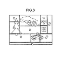
- the arrows indicated in Fig. 6 represent the motion vectors of the respective image areas grouped by the grouping unit 22.
- the motion vector quantities in the horizontal direction of the partitioned blocks constituting an image area N grouped by the grouping unit 22 are defined as H0, H1, ..., and Hm
- the motion vector quantities in the vertical direction of the partitioned blocks constituting the image area N are defined as V0, V1, ..., and Vm
- the number of partitioned blocks constituting the image area N is defined as Bk N
- the motion vector value MH N of the image area N in the horizontal direction and the motion vector value MV N in the vertical direction are obtained as follows.
- the motion vector of each of the image areas thus calculated is the resultant of the moving amount of the object contained in each of the image areas and the movement of the digital camera itself. Accordingly, the moving amount calculating unit 23 calculates the moving amount of an object contained in each of the image areas, as illustrated in Fig. 7 , by subtracting the moving amount of the digital camera itself from the motion vector of each of the image areas thus calculated.
- the moving amount in the frame image by the movement of the digital camera in the horizontal direction is expressed as GH ⁇ Z N .
- the moving amount of an object contained in each of the image areas grouped by the grouping unit 22 is calculated.
- the contrast value calculating unit 24, using the (3) contrast information calculated by the image signal processing unit 8, carries out the process of calculating a contrast value of each of the image areas grouped by the grouping unit 22. More specifically, the contrast value calculating unit 24, using the (3) contrast information calculated by the image signal processing unit 8, obtains the average value of contrast information of the partitioned blocks constituting an image area for each of the image areas grouped by the grouping unit 22. The average value of the contrast information thus obtained is defined as the contrast value of the image area.
- the contrast value MC N of the image area N is obtained as follows.
- the tracking object selecting unit 25 based on the moving amount of an object contained in each of the image areas calculated by the moving amount calculating unit 23 and the contrast value of each of the image areas calculated by the contrast value calculating unit 24, carries out the process of selecting a tracking target object. Specifically, the tracking object selecting unit 25 extracts an object that has a moving amount calculated by the moving amount calculating unit 23 exceeding a given threshold value ⁇ as a candidate for the tracking object. For example, when the moving amount of the object in the image area N is defined as V N , and if V N > ⁇ holds true, the object contained in the image area N is made to be a candidate for the tracking target. In the example depicted in Fig. 7 , each of the objects in the image areas N1, N2, and N3 are extracted as the candidates for the tracking target.
- the tracking object selecting unit 25 selects, out of the image areas of the objects selected as the candidates for the tracking target, the object in the image area that renders a maximum contrast value calculated by the contrast value calculating unit 24 as the tracking target object to be actually tracked.
- the contrast value of the image area N1 is defined as MC N1
- the contrast value of the image area N2 is defined as MC N2
- the contrast value of the image area N3 is defined as MC N3
- an automobile that is the moving object contained in the image area N1 is selected as the tracking target object.
- the tracking target object is selected from the frame image constituting the moving image.
- the object tracking operation is started by the object tracking unit 26. More specifically, the object tracking unit 26, for example, calculates the amount of characteristic as an image of the object selected as the tracking target and holds it as object information.
- the object tracking unit 26 sets a search range and searches an object that can be presumed to be the same object as the tracking target object in the set search range based on the object information.
- a focusing area is set and an AF control that focuses on the tracking target object is carried out.
- an AE control that calculates an exposure condition corresponding to the brightness of the image of the tracking target object is carried out.
- the digital camera uses the information of the luminance information, the color information, the contrast information, and the motion vector for each of the partitioned blocks in a frame image constituting a moving image, the movement of the digital camera itself due to camera shake, panning, or the like, and the focal length of the digital camera corresponding to the zooming operation so as to adequately detect a moving object in the frame image and to select it as the tracking target object.
- This allows the moving object to be set as the tracking target object without relying on the operation of the user, whereby the object tracking operation can be carried out.
- a search range of the object is set in a successive frame image centering on the position of the object detected from the current frame image.
- a moving object is set as a tracking target as in the digital camera according to the present embodiment, and if the moving amount of the object is large, the object position in the subsequent frame image may be out of the search range, thereby degrading the accuracy of search. If the search range is expanded to improve the search accuracy, the processing load required for the object tracking operation may become excessive.
- the digital camera according to the present embodiment is provided with the object position estimating unit 27, in the control calculating unit (CPU) 13, as a function to estimate the position of the tracking target object in the subsequent frame image based on the moving amount of the object calculated by the moving amount calculating unit 23.
- the object tracking unit 26 sets the search range centering on the position estimated by the object position estimating unit 27 to carry out the process of searching the tracking target object from the set search range.
- the moving amount calculating unit 23 continues to calculate the moving amount of the tracking target object for each frame even after the object tracking operation is started by the object tracking unit 26.
- the moving amounts of the object in the past frames calculated by the moving amount calculating unit 23 are stored in a memory as necessary.
- the object position estimating unit 27, as illustrated in Fig. 8 then estimates the object position in the subsequent frame image to be the position that is moved from the object position in the current frame by the moving amount of the estimated value.
- the object tracking unit 26, as indicated in Fig. 8 sets the search range of the object in the subsequent frame image centering on the object position estimated by the object position estimating unit 27. This makes it possible to improve the accuracy of the object search performed by the object tracking unit 26, thereby allowing even a fast moving object to be adequately tracked. Furthermore, the fact that the accuracy of the search range is improved allows the search range to be narrowed down to a small area, thereby reducing the processing load required for the object tracking operation and thus, speeding up the process.
- the digital camera according to the present embodiment that defines a moving object as a tracking target, when a still image is photographed at the shutter speed calculated by the AE control, and if the moving speed of the object is fast, as illustrated in Fig. 9A , the image of the object may be blurred in a photographed still image. Therefore, the digital camera according to the present embodiment is provided, in the control calculating unit (CPU) 13, with the shutter speed control unit 28 as a function to control the shutter speed at the time of photographing a still image based on the moving amount of the object calculated by the moving amount calculating unit 23.
- the control calculating unit CPU 13
- the shutter speed control unit 28 as a function to control the shutter speed at the time of photographing a still image based on the moving amount of the object calculated by the moving amount calculating unit 23.
- the shutter speed control unit 28 estimates the moving amount of the object in the subsequent frame image by carrying out a similar calculation to that of the object position estimating unit 27 based on the moving amount of the object calculated by the moving amount calculating unit 23. Alternatively, the shutter speed control unit 28 may obtain the estimated value of the moving amount of the object in the subsequent frame image calculated by the object position estimating unit 27. The shutter speed control unit 28 then controls the shutter speed at the time of photographing a still image corresponding to the moving amount of the object thus estimated when the shutter button of the digital camera is pressed by the user to photograph the still image by the image capturing element 3. More specifically, the shutter speed control unit 28 controls the shutter speed at the time of photographing the still image such that the larger the moving amount of the object is, the faster the shutter speed becomes.
- the grouping unit 22 of the control calculating unit (CPU) 13 carries out the grouping based on the color information after the grouping based on the luminance information of each of the partitioned blocks constituting a frame image is carried out.
- the grouping based on the luminance information may be carried out after the grouping based on the color information, or the grouping may be carried out by comprehensively determining the degrees of similarities in the luminance information and in the color information.
- the fact that a moving object is adequately detected from a frame image constituting a moving image and selected as a tracking target leads to an effect that the tracking operation can be started by setting the moving object as the tracking target.
Landscapes
- Engineering & Computer Science (AREA)
- Multimedia (AREA)
- Signal Processing (AREA)
- Computer Vision & Pattern Recognition (AREA)
- Physics & Mathematics (AREA)
- General Physics & Mathematics (AREA)
- Theoretical Computer Science (AREA)
- Studio Devices (AREA)
- Image Analysis (AREA)
- Exposure Control For Cameras (AREA)
- Closed-Circuit Television Systems (AREA)
Applications Claiming Priority (1)
| Application Number | Priority Date | Filing Date | Title |
|---|---|---|---|
| JP2010099936A JP5589527B2 (ja) | 2010-04-23 | 2010-04-23 | 撮像装置および追尾被写体検出方法 |
Publications (3)
| Publication Number | Publication Date |
|---|---|
| EP2381419A2 true EP2381419A2 (fr) | 2011-10-26 |
| EP2381419A3 EP2381419A3 (fr) | 2012-06-06 |
| EP2381419B1 EP2381419B1 (fr) | 2013-06-05 |
Family
ID=44312267
Family Applications (1)
| Application Number | Title | Priority Date | Filing Date |
|---|---|---|---|
| EP11163205.5A Not-in-force EP2381419B1 (fr) | 2010-04-23 | 2011-04-20 | Appareil de capture d'images, procédé de détection de suivi d'objet et produit de programme informatique |
Country Status (3)
| Country | Link |
|---|---|
| US (1) | US8599268B2 (fr) |
| EP (1) | EP2381419B1 (fr) |
| JP (1) | JP5589527B2 (fr) |
Cited By (2)
| Publication number | Priority date | Publication date | Assignee | Title |
|---|---|---|---|---|
| WO2013148591A1 (fr) * | 2012-03-28 | 2013-10-03 | Qualcomm Incorporated | Procédé et appareil de mise au point automatique d'un dispositif d'imagerie |
| CN103716541A (zh) * | 2013-12-23 | 2014-04-09 | 宇龙计算机通信科技(深圳)有限公司 | 一种拍摄大分辨率照片的方法及终端 |
Families Citing this family (30)
| Publication number | Priority date | Publication date | Assignee | Title |
|---|---|---|---|---|
| CN103889878B (zh) | 2011-10-19 | 2016-11-16 | 克朗设备公司 | 选择图像场景中彼此对应于托盘的垂直范围内的对象 |
| JP5851206B2 (ja) * | 2011-11-04 | 2016-02-03 | オリンパス株式会社 | 追尾装置及び追尾方法 |
| WO2013107037A1 (fr) * | 2012-01-20 | 2013-07-25 | Thomson Licensing | Mesure de flou |
| KR101915193B1 (ko) * | 2012-04-24 | 2018-11-05 | 한화테크윈 주식회사 | 이미지 센서를 이동시켜 영상 블러 현상을 보상하는 방법 및 시스템 |
| EP2945365B1 (fr) * | 2013-01-09 | 2021-06-16 | Sony Corporation | Dispositif de traitement d'image, méthode de traitement d'image et programme |
| JP2015014672A (ja) * | 2013-07-04 | 2015-01-22 | 住友電気工業株式会社 | カメラ制御装置、カメラシステム、カメラ制御方法、及びプログラム |
| CN105874717B (zh) * | 2014-01-15 | 2018-02-23 | 安娜卡敦设计公司 | 认知信号转换器 |
| US9792406B2 (en) | 2014-02-10 | 2017-10-17 | Neuronetics, Inc. | Head modeling for a therapeutic or diagnostic procedure |
| US9508026B2 (en) * | 2014-07-01 | 2016-11-29 | Irida Labs S.A. | System and a method for camera motion analysis and understanding from a video sequence |
| CN104469167B (zh) * | 2014-12-26 | 2017-10-13 | 小米科技有限责任公司 | 自动对焦方法及装置 |
| JP6497987B2 (ja) * | 2015-03-12 | 2019-04-10 | キヤノン株式会社 | 画像処理装置及び画像処理方法、プログラム、記憶媒体 |
| KR20170029978A (ko) * | 2015-09-08 | 2017-03-16 | 엘지전자 주식회사 | 이동단말기 및 그 제어방법 |
| JP6577852B2 (ja) * | 2015-12-03 | 2019-09-18 | キヤノン株式会社 | 動きベクトル検出装置およびその制御方法 |
| KR102462644B1 (ko) * | 2016-04-01 | 2022-11-03 | 삼성전자주식회사 | 전자 장치 및 그의 동작 방법 |
| US9990535B2 (en) | 2016-04-27 | 2018-06-05 | Crown Equipment Corporation | Pallet detection using units of physical length |
| JP6866581B2 (ja) * | 2016-06-30 | 2021-04-28 | 株式会社ニコン | 撮像装置および電子部品 |
| JP6661493B2 (ja) * | 2016-08-30 | 2020-03-11 | キヤノン株式会社 | 像ブレ制御装置、撮像装置および制御方法 |
| JP6818473B2 (ja) * | 2016-09-07 | 2021-01-20 | キヤノン株式会社 | ブレ補正装置およびその制御方法、撮像装置 |
| CN106778471B (zh) * | 2016-11-17 | 2019-11-19 | 京东方科技集团股份有限公司 | 自动跟踪购物车 |
| JP6904843B2 (ja) * | 2017-08-03 | 2021-07-21 | キヤノン株式会社 | 撮像装置およびその制御方法 |
| US10614576B2 (en) * | 2018-02-05 | 2020-04-07 | Colossio, Inc. | Method and device for partition-based image tracking |
| US20190253607A1 (en) * | 2018-02-15 | 2019-08-15 | Qualcomm Incorporated | Object tracking autofocus |
| JP7117872B2 (ja) * | 2018-03-28 | 2022-08-15 | キヤノン株式会社 | 画像処理装置、撮像装置、画像処理方法、及びプログラム |
| JP7254555B2 (ja) * | 2019-02-18 | 2023-04-10 | キヤノン株式会社 | 撮像装置および撮像装置の制御方法 |
| EP3719529A1 (fr) | 2019-03-20 | 2020-10-07 | Ricoh Company, Ltd. | Dispositif et procédé de recherche de portée |
| JP2020170252A (ja) * | 2019-04-01 | 2020-10-15 | キヤノン株式会社 | 画像処理装置、情報処理方法及びプログラム |
| KR102920736B1 (ko) * | 2020-01-29 | 2026-01-30 | 삼성전자주식회사 | 이미지의 자동 촬영 방법, 상기 방법을 수행하는 이미지의 자동 촬영 장치, 및 상기 방법을 수행하는 이미지의 자동 촬영 시스템 |
| JP7458819B2 (ja) * | 2020-02-21 | 2024-04-01 | キヤノン株式会社 | 撮像装置、制御方法、プログラム及び記憶媒体 |
| JP2021144121A (ja) * | 2020-03-11 | 2021-09-24 | キヤノン株式会社 | 表示制御装置およびその制御方法、プログラム、並びに記憶媒体 |
| CN111565300B (zh) * | 2020-05-22 | 2020-12-22 | 深圳市百川安防科技有限公司 | 基于对象的视频文件处理方法、设备及系统 |
Citations (2)
| Publication number | Priority date | Publication date | Assignee | Title |
|---|---|---|---|---|
| JP2009177503A (ja) | 2008-01-24 | 2009-08-06 | Nikon Corp | 撮像装置 |
| JP2010099936A (ja) | 2008-10-23 | 2010-05-06 | Olympus Corp | 射出成形装置 |
Family Cites Families (11)
| Publication number | Priority date | Publication date | Assignee | Title |
|---|---|---|---|---|
| JPH0651384A (ja) * | 1990-12-07 | 1994-02-25 | Olympus Optical Co Ltd | カメラのぶれ防止装置 |
| JPH0580248A (ja) | 1991-09-19 | 1993-04-02 | Ricoh Co Ltd | オートフオーカス装置 |
| JPH05107604A (ja) * | 1991-12-18 | 1993-04-30 | Minolta Camera Co Ltd | カメラ |
| JPH05288982A (ja) * | 1992-04-09 | 1993-11-05 | Olympus Optical Co Ltd | 注視点選択装置 |
| US6670963B2 (en) | 2001-01-17 | 2003-12-30 | Tektronix, Inc. | Visual attention model |
| KR100426174B1 (ko) * | 2001-10-29 | 2004-04-06 | 삼성전자주식회사 | 영상압축 알고리즘을 이용한 카메라 제어방법 |
| JP2003187248A (ja) * | 2001-12-21 | 2003-07-04 | Mitsubishi Electric Corp | 画像処理システムおよび画像処理装置 |
| JP4504158B2 (ja) * | 2004-10-29 | 2010-07-14 | オリンパス株式会社 | カメラ、追尾装置及び追尾方法並びに追尾プログラム |
| JP4329694B2 (ja) * | 2005-01-07 | 2009-09-09 | 株式会社ニコン | 撮像装置 |
| JP2007025595A (ja) | 2005-07-21 | 2007-02-01 | Fujinon Corp | オートフォーカス装置 |
| JP5045125B2 (ja) * | 2006-03-15 | 2012-10-10 | 株式会社ニコン | 被写体追尾装置および光学機器 |
-
2010
- 2010-04-23 JP JP2010099936A patent/JP5589527B2/ja not_active Expired - Fee Related
-
2011
- 2011-04-19 US US13/089,742 patent/US8599268B2/en not_active Expired - Fee Related
- 2011-04-20 EP EP11163205.5A patent/EP2381419B1/fr not_active Not-in-force
Patent Citations (2)
| Publication number | Priority date | Publication date | Assignee | Title |
|---|---|---|---|---|
| JP2009177503A (ja) | 2008-01-24 | 2009-08-06 | Nikon Corp | 撮像装置 |
| JP2010099936A (ja) | 2008-10-23 | 2010-05-06 | Olympus Corp | 射出成形装置 |
Cited By (4)
| Publication number | Priority date | Publication date | Assignee | Title |
|---|---|---|---|---|
| WO2013148591A1 (fr) * | 2012-03-28 | 2013-10-03 | Qualcomm Incorporated | Procédé et appareil de mise au point automatique d'un dispositif d'imagerie |
| CN104205801A (zh) * | 2012-03-28 | 2014-12-10 | 高通股份有限公司 | 用于使成像装置自动聚焦的方法和设备 |
| CN104205801B (zh) * | 2012-03-28 | 2018-06-26 | 高通股份有限公司 | 用于使成像装置自动聚焦的方法和设备 |
| CN103716541A (zh) * | 2013-12-23 | 2014-04-09 | 宇龙计算机通信科技(深圳)有限公司 | 一种拍摄大分辨率照片的方法及终端 |
Also Published As
| Publication number | Publication date |
|---|---|
| US8599268B2 (en) | 2013-12-03 |
| US20110261225A1 (en) | 2011-10-27 |
| JP5589527B2 (ja) | 2014-09-17 |
| EP2381419A3 (fr) | 2012-06-06 |
| EP2381419B1 (fr) | 2013-06-05 |
| JP2011233963A (ja) | 2011-11-17 |
Similar Documents
| Publication | Publication Date | Title |
|---|---|---|
| EP2381419B1 (fr) | Appareil de capture d'images, procédé de détection de suivi d'objet et produit de programme informatique | |
| US8605942B2 (en) | Subject tracking apparatus, imaging apparatus and subject tracking method | |
| US8736689B2 (en) | Imaging apparatus and image processing method | |
| US9542754B2 (en) | Device and method for detecting moving objects | |
| KR101519427B1 (ko) | 촬상 장치 및 그 셔터 구동 모드 선택 방법 | |
| US9607240B2 (en) | Image processing apparatus, image capturing apparatus, image processing method, image capturing method, and non-transitory computer-readable medium for focus bracketing | |
| EP2330812A1 (fr) | Appareil de génération d'une image panoramique, procédé de génération d'une image panoramique et support lisible sur ordinateur | |
| EP2458846B1 (fr) | Appareil de capture d'images qui détermine automatiquement le mode de tir le plus adapté à la scène de tir, procédé de contrôle associé et support de stockage | |
| JP4876065B2 (ja) | 動きベクトル検出装置及び動きベクトル検出方法及び撮像装置及びプログラム | |
| US8391699B2 (en) | Focus adjusting apparatus and focus adjusting method | |
| US11258948B2 (en) | Image pickup apparatus, control method of image pickup apparatus, and storage medium | |
| US7957633B2 (en) | Focus adjusting apparatus and focus adjusting method | |
| CN107645632A (zh) | 焦点调节设备、焦点调节方法、摄像设备和存储介质 | |
| US8855479B2 (en) | Imaging apparatus and method for controlling same | |
| KR101178777B1 (ko) | 화상 처리 장치, 화상 처리 방법 및 컴퓨터가 판독 가능한 기억 매체 | |
| US8823863B2 (en) | Image capturing apparatus and control method therefor | |
| JP2023165555A (ja) | 画像処理装置、撮像装置、制御方法及びプログラム | |
| US11206350B2 (en) | Image processing apparatus, image pickup apparatus, image processing method, and storage medium | |
| US20230066494A1 (en) | Apparatus to perform alignment to images, image processing method to perform alignment to images, and computer readable non-transitory memory to perform alignment to images | |
| JP5062095B2 (ja) | 撮像装置 | |
| US20170366738A1 (en) | Information processing apparatus, information processing method, and storage medium | |
| JP4871664B2 (ja) | 撮像装置及び撮像装置の制御方法 | |
| US20250310634A1 (en) | Display control apparatus, control method for display control apparatus, and storage medium | |
| CN120034741A (zh) | 控制设备及其控制方法、摄像设备、计算机可读存储介质和计算机程序产品 | |
| JP2019079440A (ja) | 被写体追跡装置 |
Legal Events
| Date | Code | Title | Description |
|---|---|---|---|
| 17P | Request for examination filed |
Effective date: 20110420 |
|
| AK | Designated contracting states |
Kind code of ref document: A2 Designated state(s): AL AT BE BG CH CY CZ DE DK EE ES FI FR GB GR HR HU IE IS IT LI LT LU LV MC MK MT NL NO PL PT RO RS SE SI SK SM TR |
|
| AX | Request for extension of the european patent |
Extension state: BA ME |
|
| PUAI | Public reference made under article 153(3) epc to a published international application that has entered the european phase |
Free format text: ORIGINAL CODE: 0009012 |
|
| PUAL | Search report despatched |
Free format text: ORIGINAL CODE: 0009013 |
|
| AK | Designated contracting states |
Kind code of ref document: A3 Designated state(s): AL AT BE BG CH CY CZ DE DK EE ES FI FR GB GR HR HU IE IS IT LI LT LU LV MC MK MT NL NO PL PT RO RS SE SI SK SM TR |
|
| AX | Request for extension of the european patent |
Extension state: BA ME |
|
| RIC1 | Information provided on ipc code assigned before grant |
Ipc: G06T 7/20 20060101AFI20120501BHEP Ipc: H04N 5/232 20060101ALI20120501BHEP |
|
| GRAP | Despatch of communication of intention to grant a patent |
Free format text: ORIGINAL CODE: EPIDOSNIGR1 |
|
| RIC1 | Information provided on ipc code assigned before grant |
Ipc: G06T 7/20 20060101AFI20121116BHEP Ipc: H04N 5/232 20060101ALI20121116BHEP |
|
| GRAS | Grant fee paid |
Free format text: ORIGINAL CODE: EPIDOSNIGR3 |
|
| GRAA | (expected) grant |
Free format text: ORIGINAL CODE: 0009210 |
|
| AK | Designated contracting states |
Kind code of ref document: B1 Designated state(s): AL AT BE BG CH CY CZ DE DK EE ES FI FR GB GR HR HU IE IS IT LI LT LU LV MC MK MT NL NO PL PT RO RS SE SI SK SM TR |
|
| REG | Reference to a national code |
Ref country code: GB Ref legal event code: FG4D |
|
| REG | Reference to a national code |
Ref country code: CH Ref legal event code: EP |
|
| REG | Reference to a national code |
Ref country code: AT Ref legal event code: REF Ref document number: 616038 Country of ref document: AT Kind code of ref document: T Effective date: 20130615 |
|
| REG | Reference to a national code |
Ref country code: IE Ref legal event code: FG4D |
|
| REG | Reference to a national code |
Ref country code: DE Ref legal event code: R096 Ref document number: 602011001897 Country of ref document: DE Effective date: 20130725 |
|
| REG | Reference to a national code |
Ref country code: AT Ref legal event code: MK05 Ref document number: 616038 Country of ref document: AT Kind code of ref document: T Effective date: 20130605 |
|
| RIN2 | Information on inventor provided after grant (corrected) |
Inventor name: NIINAMI, NORIKATSU |
|
| PG25 | Lapsed in a contracting state [announced via postgrant information from national office to epo] |
Ref country code: AT Free format text: LAPSE BECAUSE OF FAILURE TO SUBMIT A TRANSLATION OF THE DESCRIPTION OR TO PAY THE FEE WITHIN THE PRESCRIBED TIME-LIMIT Effective date: 20130605 Ref country code: NO Free format text: LAPSE BECAUSE OF FAILURE TO SUBMIT A TRANSLATION OF THE DESCRIPTION OR TO PAY THE FEE WITHIN THE PRESCRIBED TIME-LIMIT Effective date: 20130905 Ref country code: LT Free format text: LAPSE BECAUSE OF FAILURE TO SUBMIT A TRANSLATION OF THE DESCRIPTION OR TO PAY THE FEE WITHIN THE PRESCRIBED TIME-LIMIT Effective date: 20130605 Ref country code: SI Free format text: LAPSE BECAUSE OF FAILURE TO SUBMIT A TRANSLATION OF THE DESCRIPTION OR TO PAY THE FEE WITHIN THE PRESCRIBED TIME-LIMIT Effective date: 20130605 Ref country code: GR Free format text: LAPSE BECAUSE OF FAILURE TO SUBMIT A TRANSLATION OF THE DESCRIPTION OR TO PAY THE FEE WITHIN THE PRESCRIBED TIME-LIMIT Effective date: 20130906 Ref country code: SE Free format text: LAPSE BECAUSE OF FAILURE TO SUBMIT A TRANSLATION OF THE DESCRIPTION OR TO PAY THE FEE WITHIN THE PRESCRIBED TIME-LIMIT Effective date: 20130605 Ref country code: ES Free format text: LAPSE BECAUSE OF FAILURE TO SUBMIT A TRANSLATION OF THE DESCRIPTION OR TO PAY THE FEE WITHIN THE PRESCRIBED TIME-LIMIT Effective date: 20130916 Ref country code: FI Free format text: LAPSE BECAUSE OF FAILURE TO SUBMIT A TRANSLATION OF THE DESCRIPTION OR TO PAY THE FEE WITHIN THE PRESCRIBED TIME-LIMIT Effective date: 20130605 |
|
| REG | Reference to a national code |
Ref country code: NL Ref legal event code: VDEP Effective date: 20130605 |
|
| REG | Reference to a national code |
Ref country code: LT Ref legal event code: MG4D |
|
| PG25 | Lapsed in a contracting state [announced via postgrant information from national office to epo] |
Ref country code: RS Free format text: LAPSE BECAUSE OF FAILURE TO SUBMIT A TRANSLATION OF THE DESCRIPTION OR TO PAY THE FEE WITHIN THE PRESCRIBED TIME-LIMIT Effective date: 20130605 Ref country code: BG Free format text: LAPSE BECAUSE OF FAILURE TO SUBMIT A TRANSLATION OF THE DESCRIPTION OR TO PAY THE FEE WITHIN THE PRESCRIBED TIME-LIMIT Effective date: 20130905 Ref country code: HR Free format text: LAPSE BECAUSE OF FAILURE TO SUBMIT A TRANSLATION OF THE DESCRIPTION OR TO PAY THE FEE WITHIN THE PRESCRIBED TIME-LIMIT Effective date: 20130605 |
|
| PG25 | Lapsed in a contracting state [announced via postgrant information from national office to epo] |
Ref country code: LV Free format text: LAPSE BECAUSE OF FAILURE TO SUBMIT A TRANSLATION OF THE DESCRIPTION OR TO PAY THE FEE WITHIN THE PRESCRIBED TIME-LIMIT Effective date: 20130605 |
|
| PG25 | Lapsed in a contracting state [announced via postgrant information from national office to epo] |
Ref country code: EE Free format text: LAPSE BECAUSE OF FAILURE TO SUBMIT A TRANSLATION OF THE DESCRIPTION OR TO PAY THE FEE WITHIN THE PRESCRIBED TIME-LIMIT Effective date: 20130605 Ref country code: CZ Free format text: LAPSE BECAUSE OF FAILURE TO SUBMIT A TRANSLATION OF THE DESCRIPTION OR TO PAY THE FEE WITHIN THE PRESCRIBED TIME-LIMIT Effective date: 20130605 Ref country code: IS Free format text: LAPSE BECAUSE OF FAILURE TO SUBMIT A TRANSLATION OF THE DESCRIPTION OR TO PAY THE FEE WITHIN THE PRESCRIBED TIME-LIMIT Effective date: 20131005 Ref country code: BE Free format text: LAPSE BECAUSE OF FAILURE TO SUBMIT A TRANSLATION OF THE DESCRIPTION OR TO PAY THE FEE WITHIN THE PRESCRIBED TIME-LIMIT Effective date: 20130605 Ref country code: PT Free format text: LAPSE BECAUSE OF FAILURE TO SUBMIT A TRANSLATION OF THE DESCRIPTION OR TO PAY THE FEE WITHIN THE PRESCRIBED TIME-LIMIT Effective date: 20131007 Ref country code: SK Free format text: LAPSE BECAUSE OF FAILURE TO SUBMIT A TRANSLATION OF THE DESCRIPTION OR TO PAY THE FEE WITHIN THE PRESCRIBED TIME-LIMIT Effective date: 20130605 |
|
| PG25 | Lapsed in a contracting state [announced via postgrant information from national office to epo] |
Ref country code: PL Free format text: LAPSE BECAUSE OF FAILURE TO SUBMIT A TRANSLATION OF THE DESCRIPTION OR TO PAY THE FEE WITHIN THE PRESCRIBED TIME-LIMIT Effective date: 20130605 Ref country code: NL Free format text: LAPSE BECAUSE OF FAILURE TO SUBMIT A TRANSLATION OF THE DESCRIPTION OR TO PAY THE FEE WITHIN THE PRESCRIBED TIME-LIMIT Effective date: 20130605 Ref country code: RO Free format text: LAPSE BECAUSE OF FAILURE TO SUBMIT A TRANSLATION OF THE DESCRIPTION OR TO PAY THE FEE WITHIN THE PRESCRIBED TIME-LIMIT Effective date: 20130605 |
|
| PLBE | No opposition filed within time limit |
Free format text: ORIGINAL CODE: 0009261 |
|
| STAA | Information on the status of an ep patent application or granted ep patent |
Free format text: STATUS: NO OPPOSITION FILED WITHIN TIME LIMIT |
|
| PG25 | Lapsed in a contracting state [announced via postgrant information from national office to epo] |
Ref country code: DK Free format text: LAPSE BECAUSE OF FAILURE TO SUBMIT A TRANSLATION OF THE DESCRIPTION OR TO PAY THE FEE WITHIN THE PRESCRIBED TIME-LIMIT Effective date: 20130605 |
|
| 26N | No opposition filed |
Effective date: 20140306 |
|
| PG25 | Lapsed in a contracting state [announced via postgrant information from national office to epo] |
Ref country code: IT Free format text: LAPSE BECAUSE OF FAILURE TO SUBMIT A TRANSLATION OF THE DESCRIPTION OR TO PAY THE FEE WITHIN THE PRESCRIBED TIME-LIMIT Effective date: 20130605 |
|
| REG | Reference to a national code |
Ref country code: DE Ref legal event code: R097 Ref document number: 602011001897 Country of ref document: DE Effective date: 20140306 |
|
| PG25 | Lapsed in a contracting state [announced via postgrant information from national office to epo] |
Ref country code: LU Free format text: LAPSE BECAUSE OF FAILURE TO SUBMIT A TRANSLATION OF THE DESCRIPTION OR TO PAY THE FEE WITHIN THE PRESCRIBED TIME-LIMIT Effective date: 20140420 Ref country code: MC Free format text: LAPSE BECAUSE OF FAILURE TO SUBMIT A TRANSLATION OF THE DESCRIPTION OR TO PAY THE FEE WITHIN THE PRESCRIBED TIME-LIMIT Effective date: 20130605 |
|
| REG | Reference to a national code |
Ref country code: CH Ref legal event code: PL |
|
| REG | Reference to a national code |
Ref country code: IE Ref legal event code: MM4A |
|
| PG25 | Lapsed in a contracting state [announced via postgrant information from national office to epo] |
Ref country code: LI Free format text: LAPSE BECAUSE OF NON-PAYMENT OF DUE FEES Effective date: 20140430 Ref country code: CH Free format text: LAPSE BECAUSE OF NON-PAYMENT OF DUE FEES Effective date: 20140430 |
|
| PG25 | Lapsed in a contracting state [announced via postgrant information from national office to epo] |
Ref country code: IE Free format text: LAPSE BECAUSE OF NON-PAYMENT OF DUE FEES Effective date: 20140420 |
|
| PG25 | Lapsed in a contracting state [announced via postgrant information from national office to epo] |
Ref country code: MT Free format text: LAPSE BECAUSE OF FAILURE TO SUBMIT A TRANSLATION OF THE DESCRIPTION OR TO PAY THE FEE WITHIN THE PRESCRIBED TIME-LIMIT Effective date: 20130605 |
|
| REG | Reference to a national code |
Ref country code: FR Ref legal event code: PLFP Year of fee payment: 6 |
|
| PG25 | Lapsed in a contracting state [announced via postgrant information from national office to epo] |
Ref country code: SM Free format text: LAPSE BECAUSE OF FAILURE TO SUBMIT A TRANSLATION OF THE DESCRIPTION OR TO PAY THE FEE WITHIN THE PRESCRIBED TIME-LIMIT Effective date: 20130605 |
|
| PG25 | Lapsed in a contracting state [announced via postgrant information from national office to epo] |
Ref country code: CY Free format text: LAPSE BECAUSE OF FAILURE TO SUBMIT A TRANSLATION OF THE DESCRIPTION OR TO PAY THE FEE WITHIN THE PRESCRIBED TIME-LIMIT Effective date: 20130605 |
|
| PG25 | Lapsed in a contracting state [announced via postgrant information from national office to epo] |
Ref country code: TR Free format text: LAPSE BECAUSE OF FAILURE TO SUBMIT A TRANSLATION OF THE DESCRIPTION OR TO PAY THE FEE WITHIN THE PRESCRIBED TIME-LIMIT Effective date: 20130605 Ref country code: HU Free format text: LAPSE BECAUSE OF FAILURE TO SUBMIT A TRANSLATION OF THE DESCRIPTION OR TO PAY THE FEE WITHIN THE PRESCRIBED TIME-LIMIT; INVALID AB INITIO Effective date: 20110420 |
|
| REG | Reference to a national code |
Ref country code: FR Ref legal event code: PLFP Year of fee payment: 7 |
|
| REG | Reference to a national code |
Ref country code: FR Ref legal event code: PLFP Year of fee payment: 8 |
|
| PG25 | Lapsed in a contracting state [announced via postgrant information from national office to epo] |
Ref country code: MK Free format text: LAPSE BECAUSE OF FAILURE TO SUBMIT A TRANSLATION OF THE DESCRIPTION OR TO PAY THE FEE WITHIN THE PRESCRIBED TIME-LIMIT Effective date: 20130605 |
|
| PG25 | Lapsed in a contracting state [announced via postgrant information from national office to epo] |
Ref country code: AL Free format text: LAPSE BECAUSE OF FAILURE TO SUBMIT A TRANSLATION OF THE DESCRIPTION OR TO PAY THE FEE WITHIN THE PRESCRIBED TIME-LIMIT Effective date: 20130605 |
|
| P01 | Opt-out of the competence of the unified patent court (upc) registered |
Effective date: 20230522 |
|
| PGFP | Annual fee paid to national office [announced via postgrant information from national office to epo] |
Ref country code: FR Payment date: 20230420 Year of fee payment: 13 Ref country code: DE Payment date: 20230420 Year of fee payment: 13 |
|
| PGFP | Annual fee paid to national office [announced via postgrant information from national office to epo] |
Ref country code: GB Payment date: 20230419 Year of fee payment: 13 |
|
| REG | Reference to a national code |
Ref country code: DE Ref legal event code: R119 Ref document number: 602011001897 Country of ref document: DE |
|
| GBPC | Gb: european patent ceased through non-payment of renewal fee |
Effective date: 20240420 |
|
| PG25 | Lapsed in a contracting state [announced via postgrant information from national office to epo] |
Ref country code: DE Free format text: LAPSE BECAUSE OF NON-PAYMENT OF DUE FEES Effective date: 20241105 |
|
| PG25 | Lapsed in a contracting state [announced via postgrant information from national office to epo] |
Ref country code: GB Free format text: LAPSE BECAUSE OF NON-PAYMENT OF DUE FEES Effective date: 20240420 |
|
| PG25 | Lapsed in a contracting state [announced via postgrant information from national office to epo] |
Ref country code: FR Free format text: LAPSE BECAUSE OF NON-PAYMENT OF DUE FEES Effective date: 20240430 |
|
| PG25 | Lapsed in a contracting state [announced via postgrant information from national office to epo] |
Ref country code: GB Free format text: LAPSE BECAUSE OF NON-PAYMENT OF DUE FEES Effective date: 20240420 Ref country code: FR Free format text: LAPSE BECAUSE OF NON-PAYMENT OF DUE FEES Effective date: 20240430 Ref country code: DE Free format text: LAPSE BECAUSE OF NON-PAYMENT OF DUE FEES Effective date: 20241105 |