EP2381991B1 - Gerät mit einem abgestuften Mundstück zur Abgabe eines Arzneimittels in Aerosolform - Google Patents
Gerät mit einem abgestuften Mundstück zur Abgabe eines Arzneimittels in Aerosolform Download PDFInfo
- Publication number
- EP2381991B1 EP2381991B1 EP09768237A EP09768237A EP2381991B1 EP 2381991 B1 EP2381991 B1 EP 2381991B1 EP 09768237 A EP09768237 A EP 09768237A EP 09768237 A EP09768237 A EP 09768237A EP 2381991 B1 EP2381991 B1 EP 2381991B1
- Authority
- EP
- European Patent Office
- Prior art keywords
- mouthpiece
- patient
- back end
- inlet port
- aerosol
- Prior art date
- Legal status (The legal status is an assumption and is not a legal conclusion. Google has not performed a legal analysis and makes no representation as to the accuracy of the status listed.)
- Active
Links
Images


Classifications
-
- A—HUMAN NECESSITIES
- A61—MEDICAL OR VETERINARY SCIENCE; HYGIENE
- A61M—DEVICES FOR INTRODUCING MEDIA INTO, OR ONTO, THE BODY; DEVICES FOR TRANSDUCING BODY MEDIA OR FOR TAKING MEDIA FROM THE BODY; DEVICES FOR PRODUCING OR ENDING SLEEP OR STUPOR
- A61M15/00—Inhalators
-
- A—HUMAN NECESSITIES
- A61—MEDICAL OR VETERINARY SCIENCE; HYGIENE
- A61M—DEVICES FOR INTRODUCING MEDIA INTO, OR ONTO, THE BODY; DEVICES FOR TRANSDUCING BODY MEDIA OR FOR TAKING MEDIA FROM THE BODY; DEVICES FOR PRODUCING OR ENDING SLEEP OR STUPOR
- A61M15/00—Inhalators
- A61M15/0001—Details of inhalators; Constructional features thereof
- A61M15/0021—Mouthpieces therefor
-
- A—HUMAN NECESSITIES
- A61—MEDICAL OR VETERINARY SCIENCE; HYGIENE
- A61M—DEVICES FOR INTRODUCING MEDIA INTO, OR ONTO, THE BODY; DEVICES FOR TRANSDUCING BODY MEDIA OR FOR TAKING MEDIA FROM THE BODY; DEVICES FOR PRODUCING OR ENDING SLEEP OR STUPOR
- A61M11/00—Sprayers or atomisers specially adapted for therapeutic purposes
- A61M11/005—Sprayers or atomisers specially adapted for therapeutic purposes using ultrasonics
-
- A—HUMAN NECESSITIES
- A61—MEDICAL OR VETERINARY SCIENCE; HYGIENE
- A61M—DEVICES FOR INTRODUCING MEDIA INTO, OR ONTO, THE BODY; DEVICES FOR TRANSDUCING BODY MEDIA OR FOR TAKING MEDIA FROM THE BODY; DEVICES FOR PRODUCING OR ENDING SLEEP OR STUPOR
- A61M15/00—Inhalators
- A61M15/009—Inhalators using medicine packages with incorporated spraying means, e.g. aerosol cans
-
- A—HUMAN NECESSITIES
- A61—MEDICAL OR VETERINARY SCIENCE; HYGIENE
- A61M—DEVICES FOR INTRODUCING MEDIA INTO, OR ONTO, THE BODY; DEVICES FOR TRANSDUCING BODY MEDIA OR FOR TAKING MEDIA FROM THE BODY; DEVICES FOR PRODUCING OR ENDING SLEEP OR STUPOR
- A61M2202/00—Special media to be introduced, removed or treated
- A61M2202/06—Solids
- A61M2202/064—Powder
-
- A—HUMAN NECESSITIES
- A61—MEDICAL OR VETERINARY SCIENCE; HYGIENE
- A61M—DEVICES FOR INTRODUCING MEDIA INTO, OR ONTO, THE BODY; DEVICES FOR TRANSDUCING BODY MEDIA OR FOR TAKING MEDIA FROM THE BODY; DEVICES FOR PRODUCING OR ENDING SLEEP OR STUPOR
- A61M2206/00—Characteristics of a physical parameter; associated device therefor
- A61M2206/10—Flow characteristics
- A61M2206/11—Laminar flow
Definitions
- the invention of the present application relates to an apparatus to aid in administering inhaled pharmaceutical aerosol to a patient.
- IPAs inhaled pharmaceutical aerosols
- a perennial problem with the use of inhalers is the low efficiency of the delivery of the aerosol to its target.
- MDI meter dose inhalers
- DPI dry powder inhalers
- Methods to improve lung deposition include patient education, for example, teaching patients about optimal positioning of the inhaler mouthpieces, coordinating of actuation of an inhalers with inhalation, ensuring the patient lips make an effective seal around the mouthpiece of the inhaler, ensuring that the patient places their teeth around the mouthpiece to prevent deposition on the teeth.
- Other methods include the use of a spacer placed between an inhaler mouthpiece and the mouth of a patient, and redesigning of mouthpieces of inhalers so as to reduce drug deposition on the mouthpieces.
- U.S. Patent No. 7,331,349 to Brady et al. provides for a method of treating snoring or sleep apnea by advancing the mandible by the use of an extra-oral device.
- U.S. Patent No. 7,311,103 to Jeppesen provides for a method of treating Obstructive Sleep Apnea Syndrome utilizing positive airway pressure by creating a single-piece, dual arch airway orthotic, using said orthotic to obturate the oral cavity via an acrylic seal between the upper and lower dental arches.
- U.S. Patent Nos. 5,645,423 and 5,645,424, both to Collins disclose orthodontic appliances comprising a set of pivotable segments that may be affixed to opposing upper and lower teeth on one side of patient's dental arch to cause mandible advancement.
- a device for administering aerosol is further disclosed in US-2007/0039614 .
- the present invention provides an apparatus to aid aerosol delivery to a patient. More specifically, the present invention is directed to such apparatus which comprises a front end, a back end, a top side, a bottom side, a bore through the apparatus from the front end to the back end, an upper step on the top side facing to the back end; and a lower step on the bottom side facing to the front end, wherein the upper step is further towards the back end than is the lower step.
- the position of the two steps to each other is defined as the step offset such that upon insertion of the back end of the apparatus into the patient's mouth and biting down the upper and lower step cause mandibular advancement.
- the front end of the apparatus comprises an inlet port.
- Such an inlet port may be adapted to attach to an inhaled pharmaceutical aerosol delivery device.
- the inhaled pharmaceutical aerosol delivery device may be an inhaler.
- the object of the present invention is also to provide for the dimensions of the step offset.
- the step offset has a value between -3 mm and +6 mm.
- the step offset is a non-negative value.
- the step offset has a positive value.
- the step offset is between +3 and +6 mm.
- Another object of the present invention is to provide for an apparatus to aid aerosol delivery to a patient comprising a front end, and a back end, a bore through the apparatus from the front end to the back end, wherein the apparatus is further adapted to receive lower and upper teeth of a patient, such that upon insertion of the back end of the tube into the patient's mouth and biting down on the tube causes mandibular advancement.
- This mandibular advancement opens the upper airway of the patient, which in turn improves the laminar flow of inhaled pharmaceutical aerosol through the airway, hence increasing lung deposition of inhaled pharmaceutical aerosol.
- a mouthpiece is a part of any device, which is introduced into a patient's mouth.
- the mouthpiece of the present invention comprises a back end, a top side, a bottom side, an upper step on the top side, a lower step on the bottom side.
- the upper step faces backwards, and the lower step faces forwards.
- the upper step is further towards the back end than is the lower step.
- the mouthpiece may be attached to an aerosol delivery device, such as an inhaler.
- One of the embodiments of the present invention is a metered dose inhaler comprising a stepped mouthpiece.
- Another embodiment of the present invention is a dry powder inhaler comprising a stepped mouthpiece.
- Yet another embodiments of the present invention is a nebulizer comprising a stepped mouthpiece.
- FIG. 1 is a right perspective view of an embodiment of an apparatus of the present invention.
- FIG. 2 is a side elevation view of an embodiment of an apparatus of the present invention.
- FIG. 3 is a top view of an embodiment of an apparatus of the present invention.
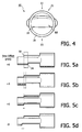
- FIG. 4 is a front view of an embodiment of an apparatus of the present invention, looking from the front of the apparatus.
- FIG. 5 is a side elevation view of four different embodiments of an apparatus of the present invention, showing various step offset values.
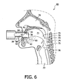
- FIG. 6 shows a use of an apparatus of the present invention by a patient.
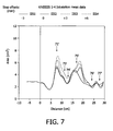
- FIG. 7 shows four pharyngograms of four apparatuses with the same small cross section and with differing step offsets for a typical patient.
- FIG. 8 shows four pharyngograms of four apparatuses with the same medium sized cross section and with differing step offsets for a typical patient.
- FIG. 9 shows four pharyngograms of four apparatuses with the same large cross section and with differing step offsets for a typical patient.
- FIG. 10 shows four pharyngograms of four apparatuses with the same small cross section and with differing step offsets for a patient who suffers from sleep apnea.
- FIG. 11 shows a perspective view of an embodiment of the present invention comprising a metered dose inhaler with a stepped mouthpiece.
- FIG. 12(a) shows a perspective view of an embodiment of the present invention comprising a dry powder inhaler with a stepped mouthpiece.
- Fig. 12(b) shows a side elevation view of an embodiment of the present invention comprising a portion of a nebulizer with a stepped mouthpiece.
- the apparatus of the present invention comprises a mouthpiece of such configuration, that when a patient uses the apparatus properly, the mouthpiece will force the patient's lower jaw into a position to increase the deposition of inhaled pharmaceutical aerosol into the patient's lung.
- the apparatus of the present invention increases the deposition of the inhaled pharmaceutical aerosol in the patient's lungs by improving the geometry of the oral cavity of the patient to cause a laminar flow of an air /inhaled pharmaceutical aerosol mixture. Positioning the patient's jaw and related anatomical structure in an appropriate way will decrease the deposition of inhaled pharmaceutical aerosol particle in the upper airway, and increase the deposition in the lungs.
- FIGS 1 to 5 illustrate an exemplary embodiment of an apparatus 10 according to one embodiment of the present invention.
- Apparatus 10 comprises a hollow body 11 with a front end 12, and back end 30 with an imaginary axis 50 leading through hollow body 11.
- Apparatus 10 comprises a shaft 20 with a mouthpiece 31 on back end 30, and an inlet port 13 at front end 12.
- Apparatus 10 also comprises a bore 60 through the apparatus from front end 12 to the back end 30. Bore terminates on front end 12 with inlet aperture 16, and on back end 30 with outlet aperture 36.
- Apparatus 10 comprises a unitary body which may be formed from a suitable material.
- Suitable materials may be any biocompatible material, which is acceptable for a safe and effective use by a patient or a medical professional. Any commonly used material in the art of inhaled pharmaceutical aerosols delivery may be used.
- the material should also provide a relatively rigid structure to the mouthpiece so that a patient does not deform the mouthpiece during the use thereof.
- a suitable material may be a thermoset plastic, such as acrylonitrile butadiene styrene, poly(methyl methacrylate), polyacrylate, polyethylene, polypropylene, polybutylene, polysulfone, polyphthalamide, polystyrene, polyurethane, polyvinyl chloride, styrene acrylonitrile resin, or copolymers thereof.
- the suitable material is polyethylene, polypropylene, polyurethane or polycarbonate.
- the suitable material is polyethylene, or polypropylene.
- Apparatus 10 may be formed by any means in the art used to form mouthpieces of medical devices.
- the mouthpiece is formed by reaction injection molding.
- apparatus 10 is a unitary body.
- the apparatus is assembled from a plurality of structural elements forming the parts of apparatus 10.
- the individual elements may be formed by molding or otherwise forming independently from one another and are subsequently bonded together to form apparatus 10. Such bonding may be permanent, or alternatively, the individual elements may be friction fitted together and may be readily disassembled for easier cleaning of the apparatus.
- the apparatus is generally rigid in nature. It is necessary that apparatus 10 be rigid, so that apparatus 10 does not deform during the use of apparatus 10. Specifically, when a patient bites on mouthpiece 31, the mouthpiece does not constrict the inner cross-section of shaft 20. Further, inlet port 13 should also be rigid as to readily accept an exhaust outlet from an inhaler or a spacer.
- Inlet port 13 functions as a receiving inlet for inhaled pharmaceutical aerosols or medical gases through an inlet aperture 16.
- inlet port 13 is defined by a cylindrical projecting wall 14 defining an interior volume. The interior of the inlet port is fluidly connected to the interior of shaft 20.
- the projecting wall surrounding the interior volume has a shape of a right circular cylinder.
- the projecting wall surrounding the interior volume of the inlet port has a frustal conical shape with the wall slightly angled inward, as to allow for an easier mating with an outlet port of an inhaler device.
- the projecting wall surrounding the interior volume of the inlet port has a frustal conical shape with the wall slightly angled outward to allow for an alternative mating with an outlet port of an inhaler device.
- the projecting wall surrounding the interior volume of the inlet port has a general right cylinder shape; examples of general right cylinder shape includes an elliptic cylinder.
- Projecting wall 14 terminates on front end 12 with a peripheral edge 15.
- peripheral edge 15 is generally smooth with slightly rounded corners to ensure that a patient or a medical professional does not cut themselves on the corners, and to aid in mating of an outlet port of an inhaler to the inlet port.
- the peripheral edge has sharp corners.
- an inhaled pharmaceutical aerosol delivery device is a device which either generates stored inhaled pharmaceutical aerosol upon actuation to deliver inhaled pharmaceutical aerosol out of an outlet port, or alternatively, is a device through which inhaled pharmaceutical aerosol flows through to an outlet port.
- inhaled pharmaceutical aerosol delivery device includes an inhaler (commonly referred to as a puffer), and a spacer.
- an inhaler include metered dose inhalers (MDI), dry powder inhalers (DPI), or a nebulizer.
- nebulizers include pneumatic nebulizers, ultrasonic nebulizers, and mesh nebulizers.
- An inhaled pharmaceutical aerosol delivery device also includes devices that deliver condensation aerosols and electrohydrodynamic aerosols.
- the apparatus embodiment of the present invention is designed to be used in concert with a metered dose inhaler.
- metered dose inhalers include, but are not limited to, those sold under the tradenames AiromirTM, Ventolin®, Atrovent®, Becloforte®, Benclovent®, Berotec®, Combivent®, Flovent®, Tilade®, Serevent®, Intal®, Vanceril®, and QVAR®.
- the apparatus of the present invention is also designed to be used with a spacer.
- a spacer device is designed to make the use of an inhaler much more effective and easier. Also known as an asthma spacer, it is an empty chamber with an inlet port and an outlet port. The use of such spacer devices partially mitigates the difficulty of coordinating the timing of the inhaler actuation and the patient's inhalation. Furthermore, the use of such spacer devices slows down the speed of delivery of the pharmaceutical aerosol into the mouth so that lower percentage of the pharmaceutical aerosol deposits in the oropharynx.
- a spacer device has a chamber that fits on the mouthpiece of the inhaler, a mouthpiece of the spacer is placed between patient's lips. The pharmaceutical aerosol is sprayed directly into the chamber of the spacer instead of the patient's mouth. The pharmaceutical aerosol is then inhaled with a slow deep breath.
- a spacer may be commercially obtained, or it may be homemade.
- Spacer devices available to asthma patients include, but are not limited to, ACE® Spacer (DHD Healthcare, Wampsville, New York, USA), Aerochamber® (Forest Pharmaceuticals, St Louis, Missouri, USA), Easivent Spacer, EZ-Spacer® (WE Pharmaceuticals, Ramona, California, USA), Inspirease® (Key Pharmaceuticals, Kenilworth, New Jersey, USA), AirLifeTM Medispacer® (Allegiance Healthcare Corporation, McGaw Park, Illinois, USA); LiteAire® (Thayer Medical, Arlington, Arizona, USA), Optichamber® Advantage Valved Holding Chamber (Respironics HealthScan Asthma and Allergy Products, Cedar Grove, New Jersey, USA), Nebuhaler® (AstraZeneca, UK), VentaHaler Spacer Device, RiteFlo SpacerTM, Volumatic®, Babyhaler®, and Nebuchamber®.
- the invention of the present application can be used with any device that delivers inhaled pharmaceutical aerosol.
- inhaled pharmaceutical aerosol refers to any type of medicament that is formulated to be delivered to a patient in aerosolized form into the patient's lungs.
- aerosol refers to a suspension of solid, solution or liquid particles in a gas.
- aerosol also refers to a suspension of a mixture of solid and liquid particles in a gas.
- aerosol also refers to liquid particles in a gas, wherein the liquid is a mixture of at least two liquids. Such a mixture can be a homogenous liquid (such as a solution), or it can be a heterogeneous liquid (such as a suspension).
- the apparatus of the present invention is designed to work with any aerosol of any common particle size.
- the mean aerosol particle size is 0.1 to 10 micrometers.
- the mean aerosol particle size is 0.5 to 5 micrometers.
- the aerosol particle size is submicron size.
- An example of particles with submicron size are nanoparticles.
- an outlet port of the inhaled pharmaceutical aerosol delivery device is friction fitted through inlet aperture 16 into inlet port 13 of apparatus 10.
- an outer surface of the outlet port is in contact with the inner surface 17 of projecting wall 14.
- inner surface 17 of projecting wall 14 is smooth. Such smoothness aids in the mechanism of friction fitting.
- inner surface 17 has geometric features which help to retain the outlet port of the inhaled pharmaceutical aerosol delivery device so it is matched to the corresponding features on the outlet port of the inhaled pharmaceutical aerosol delivery device. Such geometric features include ridges and other protruding features, and valleys and other intruding features. Such geometric features on the inner surface 17 in such embodiment are coordinated to the matching features on the outer surface of the outer port of inhaled pharmaceutical aerosol delivery device.
- the outlet port of the inhaled pharmaceutical aerosol delivery device fits over inlet port 13; namely, outer surface 18 of projecting wall 14 is in contact with the inner surface of the wall of the outlet port of the inhaled pharmaceutical aerosol delivery device.
- outer surface 18 has geometric features which help to retain the outlet port of the inhaled pharmaceutical aerosol delivery device by matching to the corresponding feature on the outlet port of the inhaled pharmaceutical aerosol delivery device.
- Such geometric features include ridges and other protruding features, and valleys and other intruding features.
- Such geometric features on the outer surface 18 in such embodiment are coordinated to the matching features on the inner surface of the outer port of inhaled pharmaceutical aerosol delivery device.
- Shaft 20 is attached on one end to inlet port 13, and terminates on the other end with a mouthpiece 31.
- Shaft 20 is hollow and is in fluid contact with inlet port 13.
- the cross-section of the shaft can be of any two dimensional shape, so long as that it of sufficient size for a mouthpiece to fit into a patient's mouth to deliver the inhaled pharmaceutical aerosol.
- shaft 20 has an elliptic cross-section.
- the minor axis of the ellipse that defines the cross-section of the shaft is in the vertical direction
- the major axis of the ellipse that defines the cross-section of the shaft is in the horizontal direction.
- the cross-section of the shaft may be circular, ellipsoidal, oval, square, square with rounded corners, square with four curvilinear edges, rectangular, rectangular with rounded edges, rectangular with two curvilinear edges, or rectangular with four curvilinear edges, among others.
- the area of the cross section of bore 60 at narrowest point of bore 60 is defined as the cross section. Such cross section is measured in mm 2 .
- the size of cross section area in the apparatus of the present invention may be between 50 and 500 mm 2 , preferably between 100 and 300 mm 2 .
- the apparatus needs to be positioned between the upper and lower teeth of the patient. It is beneficial that the patient takes the apparatus into his/her mouth and introduces the inhaled pharmaceutical aerosol into the inlet port as for the inhaled pharmaceutical aerosol to flow through the device into the mouthpiece, into the patient's oral cavity, and finally into the patient's lungs. To achieve proper orientation of the apparatus by the patient, in a preferred embodiment markings on the apparatus are oriented towards the patient. Furthermore, in a preferred embodiment, only the inlet port 13 is capable of mating with an outlet port of an inhaled pharmaceutical aerosol delivery device and not mouthpiece 31 of the apparatus 10.
- shaft 20 has a top side 21 and a bottom side 22. Both top side 21 and bottom side 22 stretch from a border between shaft 20 and inlet port 13, to peripheral edge 37 of mouthpiece 31.
- the apparatus 10 needs to be positioned between the upper and lower teeth of the patient properly. It is beneficial that the patient places top side 21 of shaft 20 with contact with his/her top teeth, and bottom side 22 of shaft 20 with his/her bottom teeth. Placing the apparatus 10 into the patients mouth upside down would likely result in sub-optimal lung deposition of inhaled pharmaceutical aerosol.
- top side 21 is marked to indicate to the user of the apparatus the axial orientation of apparatus 10. Such markings may be in form of writing, symbols, or juvenile drawings, although any suitable indicia may be used.
- Mouthpiece 31 is the portion of shaft 20 which is introduced into the oral cavity of the patient. Mouthpiece 31 also comprises outlet aperture 36, through which inhaled pharmaceutical aerosol is introduced into the oral cavity of a patient.
- mouthpiece 31 comprises upper step 32, and lower step 34.
- Upper step 32 is a step on top side 21 of shaft 20.
- Upper step 32 faces towards back end 30 of apparatus 10, meaning that looking from back end 30 towards front end 12, riser 33 of upper step 32 is visible.
- Lower step 34 is a step on bottom side 22 of shaft 20.
- Lower step 34 faces forward (towards front end 12 ), meaning that looking along the bottom side 22 from front end 12 towards back end 30, riser 35 of lower step 34 is visible.
- Mouthpiece 31 further comprises an area 38 where the patient's upper teeth are placed, and an area 39 where the patient's lower are placed.
- the upper front teeth are placed so that the upper front teeth of the patient are contacted with top side 21 and the apparatus is manipulated so that the front of the upper front teeth are pushed against upper riser 33.
- the incisal surfaces of the maxillary central incisors connect with area 38, while at the same time the facial surfaces (also referred to as the buccal surfaces) of the maxillary central incisors connect with riser 33.
- at least one of the incisal surfaces of at least one of the maxillary lateral incisor also connect with area 38.
- At least one of the facial surfaces of at least one the maxillary lateral incisors also connect with riser 33.
- the incisal surface of at least one of the maxillary lateral incisors connects with area 38, while at the same time the facial surface of at least one the maxillary lateral incisors also connect with riser 33.
- the incisal surfaces of at least one of the mandibular central incisors or mandibular lateral incisors connect with area 39, while at the same time at least one of the lingual surfaces of the mandibular central incisors or mandibular lateral incisors connect with lower riser 35. Any combination of simultaneous connections of incisal surfaces of mandibular incisors with area 39 and connections of lingual surfaces of mandibular incisors with lower riser 35 are satisfactory for the purposes of the present invention.
- the term "contact" of a tooth surface with a surface of the apparatus 10 does not necessarily mean a full or a complete matching of the tooth surface with a portion of the surface of the apparatus. It is sufficient if only a small portion, such as a single point, of the tooth surface contacts a small portion of the surface of the apparatus 10.
- Upper riser 33 also includes edge 41 of upper step 32.
- lower riser 35 also includes edge 42 of lower step 34.
- the facial surface of a maxillary incisor can contact upper riser 33 only on edge 41 of upper step 32.
- the lingual surface of a mandibular incisor can contact lower riser 35 on edge 42 of lower step 34.
- Step offset measured in millimeters, is the distance along the axis 50, between the position of the upper step 32 relative to the lower step 34.
- Step offset value of 0 mm as illustrated in Fig. 5(c) , means that upper step 32 is aligned with lower step 34.
- a positive offset value such as in Figs. 5(a) and 5(b) indicates that upper step 32 is further back along axis 50 (i.e., closer to back end 30 of mouthpiece 31 ) than is lower step 34.
- the phrase "further back” or “further towards the back end” indicates the position of the steps relative to each other with respect to the axis 50 passing through the center of the apparatus 10.
- the position of the intersection of an imaginary right angle projection line from the axis 50 of the apparatus 10 to the center of one step is compared to the position of the intersection of an imaginary right angle projection line from the axis 50 of the apparatus 10 to the center of the other step.
- the step of which the intersection of the projection line is further back along the axis of the apparatus is considered to be further back, or further towards the back end 30 of the apparatus 10.
- the stepped mouthpiece may also be incorporated into the structure of an inhaled pharmaceutical aerosol delivery device.
- the inhaled pharmaceutical aerosol delivery device comprising the stepped mouthpiece is a metered dose inhaler.
- a metered dose inhaler comprises at least two components: a canister, and an actuator.
- the canister contains a drug which is to be delivered to patient's lungs, a liquified gas propellant, and other excipients, such as a stabilizer.
- the canister also comprises a metering dose valve with an actuating stem.
- the actuator comprises a discharge nozzle which mates with the actuating stem.
- the patient using the inhaler presses down on the top of the canister, while supporting the lower portion of the actuator. Actuation of the device releases a single metered dose of liquid propellant that contains the drug.
- a breakup of the volatile propellant into droplets, followed by rapid evaporation of the droplets yields micron-sized particles aerosol particles containing the drug.
- the peripheral edge of the mouthpiece of the present invention can have any shape appropriate to define the outlet aperture.
- the shape of the outlet aperture is convex.
- the outlet aperture can have a shape of a circle, an ellipse, an oval, a square, a square with rounded corners, a square with four curvilinear edges, a rectangle, a rectangle with rounded edges, a rectangle with two curvilinear edges, a rectangle with four curvilinear edges, or other similar shapes.
- Metered dose inhaler 80 comprises canister 81, and actuator 82.
- the actuator comprises mouthpiece 83, which at back end 84, contains outlet aperture 85, defined by peripheral edge 86.
- the mouthpiece further comprises an upper step 87 on upper side 88 of mouthpiece 83, and lower step 89 on lower side 90 of mouthpiece 83.
- the exemplary embodiment in Figure 11 shows the shape of aperture 85 defined by peripheral edge 86 as a square with four curvilinear edges.
- the stepped mouthpiece is incorporated into the structure of a dry powder inhaler.
- Any dry powder inhaler in which a patient places a mouthpiece of the dry powder inhaler between the patient's teeth is may be adapted to incorporate the stepped mouthpiece.
- a dry powder inhaler may be a single-dose device, or a multiple-dose device. Examples of dry powder inhalers include Aerolizer®, HandiHalerTM, Flexhaler®, Disks®, and Twisthaler®.
- Dry powder inhaler 100 comprises mouthpiece 101, which at back end 102, contains outlet aperture 103, defined by peripheral edge 104.
- the mouthpiece further comprises an upper step 105 on upper side 106 of mouthpiece 101, and lower step 107 on lower side 108 of mouthpiece 101.
- the exemplary embodiment in Figure 12(a) shows the shape of aperture 103 defined by peripheral edge 104 as a circle.
- the stepped mouthpiece is incorporated into the structure of a nebulizer.
- Any nebulizer in which a patient places a mouthpiece of the nebulizer between the patient's teeth is may be adapted to incorporate the stepped mouthpiece.
- nebulizers of the present invention which comprise stepped mouthpieces include pneumatic nebulizers, ultrasonic nebulizers, and mesh nebulizers.
- Nebulizers of the present invention which comprise stepped mouthpieces also include devices that deliver condensation aerosols and electrohydrodynamic aerosols.
- Nebulizer outlet tube 110 comprises mouthpiece 111, which at back end 112, contains outlet aperture 113.
- the mouthpiece further comprises an upper step 115 on upper side 116 of mouthpiece 111, and lower step 117 on lower side 118 of mouthpiece 111.
- Nebulizer outlet tuber 110 is connected to the rest of the nebulizer by tubing 119.
- the optimal offset varies with each patient.
- the optimal step offset may be +2 mm, with others, it may be +5 mm.
- typically the upper practical limit of step offset is about +7 mm.
- the step offset has a value between -3 mm and +6 mm.
- the step offset is a non-negative value.
- the step offset has a positive value.
- the step offset is between +3 and +6 mm.
- mandibular advancement is patient dependent, and that an optimal value of mandibular advancement in order to maximize inhaled pharmaceutical aerosol lung deposition may be found anywhere along the mandibular advancement axis, ranging between no advancement and maximum advancement. Advancing the mandible too much or not enough may constrict the oropharyngeal cross-section.
- the optimal mandibular advancement may be achieved by using a mouthpiece where the step offset is negative.
- the negative offset may be used, for example, by a patient suffering from a case of mandibular prognathism wherein the mandible is naturally advanced so as to constrict the oropharyngeal cross-section.
- mandibular advancement in absolute terms is greater than the step offset.
- a step offset of 0 mm means that the steps are lined up; however, using a mouthpiece comprising a 0 mm mouthpiece actually advances the lower teeth over the upper teeth.
- the lingual surfaces of mandibular incisors line up with facial surfaces of maxillary incisors, thus in effect the mandibular incisors appear to be advanced compared to the maxillary incisors.
- the maxillary incisors overlap mandibular incisors; hence the jaw must advance in order for the incisors to even line up with each other, and advance even more for the lingual surfaces of mandibular incisors line up with facial surfaces of maxillary incisors.
- the cross-section area of the mouthpiece is another important parameter for construction of a mouthpiece of the invention.
- the cross section has an elliptical shape, with an axis in the horizontal plane, and an axis in the vertical plane.
- the horizontal axis may be larger than the vertical axis.
- the horizontal axis may be smaller than the vertical axis.
- the horizontal axis may be any length which may be practicable; in preferred embodiments the length of the horizontal axis is between 15 and 30 mm.
- the vertical axis may be any length which may be practicable; in preferred embodiments the length of the vertical axis is between 0 and 40 mm.
- FIG. 6 illustrates a typical use of the apparatus with a positive offset as used by a patient.
- Apparatus 10 held by patient 60, clamped down between the patient's maxillary incisors 61, and mandibular incisors 62.
- Figure 6 shows one embodiment of the use, namely, incisal surface 63 of maxillary incisor 61 connects with area 38, facial surface 64 of maxillary incisor 61 connects with upper riser 33, incisal surface 65 of mandibular incisor 62 connects with area 39, and lingual surface 68 connects with edge 42.
- Figure 6 also shows the geography of the airway 70 which is used to deliver the inhaled pharmaceutical aerosol to the lungs.
- Airway 70 comprises oral cavity 71, oropharyngeal junction 72, oropharynx 73, epiglottis 74, hypopharynx 75, glottis 76, and larynx 77. Because the nasal cavity is not directly involved in the delivery of inhaled pharmaceutical aerosol to the lungs, for the purposes of the description of the present invention, nasal cavity 78 is omitted from the definition of airway 70.
- One of the advantage of the stepped mouthpiece in any of the embodiments discussed herein is that the use of such a device results in combined opening and advancement of the jaw.
- This combined opening and advancement of the jaw not only opens the airway, but also causes an appropriate positioning of the patient's tongue.
- the combined horizontal and vertical movement of a patient's jaw resulting in the use of the mouthpiece of the present invention appears to eliminate the problem of the tongue arch and leaves the tip of the tongue free.
- the apparatus of the present invention, and the mouthpiece of the present invention are a result of scientific studies into methods of improving inhaled pharmaceutical aerosol lung deposition.
- Lung scintigraphy studies using different breathing maneuvers to control parameters such as inhalation cross-sectional area, time and flow rate were performed.
- Oropharyngeal deposition is not desired, because any deposition in oropharynx means poorer deposition of the inhaled pharmaceutical aerosol in lungs.
- the geography of the upper airway may be measured by an acoustic pharyngometer.
- an acoustic pharyngometer affords the ability to objectively evaluate and document the pharyngeal airway.
- This physiological tool comprises of a wavetube housing a loudspeaker, two microphones recording the resulting incident and reflected sound waves, and a computer to record and interpret the resulting data. See J. S. Viviano, Assessing Orthotic Normalization of Pharyngeal Dynamics, J. Craniomandibular Practice July 2004, vol. 22, no. 3, pp 192 to 208 .
- a pharyngogram an output of the pharyngometer, shows graphically the geometry of the pharyngeal airway.
- the pharyngogram represents a cross-sectional area of the airway from the oral cavity caudal to the glottis.
- the area under the curve represents the volume over a given length of airway, and landmarks along the pharyngogram relate to specific anatomical landmarks.
- acoustic pharyngometer to investigate inhaled pharmaceutical aerosol deposition in the lungs is novel.
- the use of acoustic pharyngometer has been confined to investigation of sleep apnea or snoring. See, for example, K. Monahan et al., Oropharyngeal Dimensions in Adults: Effect of Ethnicity, Gender, and Sleep Apnea, J. Clin. Sleep Medicine 2005, vol. 1, no. 3, pp 257 to 263 ; and J. S. Viviano, Acoustic Reflection: Review and Clinical Applications for Sleep Disordered Breathing, Sleep and Breathing 2002, vol. 6, No. 3, 2002 .
- the data from the acoustic pharyngometer has been obtained during the exhalation portion of subjects' breaths; in the experiment to measure the geography of patient airway for the purposes of investigating inhaled pharmaceutical aerosol lung deposition, the data was collected during the inhalation portion of subjects' breaths.
- the three cross-sectional areas of the apparatus were 161 mm 2 (the area of an ellipse with the minor axis laying in the vertical direction and measuring 10 mm, and the major axis laying in the horizontal direction and measuring 28 mm), 232 mm 2 , (15 mm x 28 mm) and 278 mm 2 (20 mm x 28 mm).
- the four step offsets were -3 mm, 0 mm, +3 mm and +6 mm.
- Pharyngograms of four different patients for each of the twelve apparatuses was obtained. Data was obtained at approximately 0.42 cm intervals. Four runs were made for each patient for each apparatus.
- Figures 7 to 9 Typical pharyngograms are presented in Figures 7 to 9 .
- Figure 7 show four curves representing four different step offsets for apparatuses with 161 mm 2 cross section for a typical patient.
- Figure 8 show four curves representing four different step offsets for apparatuses with 232 mm 2 cross section for the same patient.
- Figure 9 show four curves representing four different step offsets for apparatuses with 278 mm 2 cross section for the same patient.
- the peaks and valleys of the curves in Figure 7 are indicative of the geography of the patient's airway.
- the distance along the vertical axis represents the distance along the air pathway measured in cm from the patient's teeth.
- the first large peak, labeled 71' corresponds to the patient's oral cavity
- shoulder 73' corresponds to the oropharynx
- valley 74' corresponds to the epiglottis
- large peak 75' corresponds to the hypopharynx
- valley 76' corresponds to the glottis
- features 77' correspond to the features in larynx.
- Figure 7 shows that with increasing step offset not only does the oral cavity open, but surprisingly, the cross section of hypopharynx increases. This is also observed in Figures 8 and 9 . These graphs thus demonstrate that show that the cross section of the oral cavity increases with larger step offset. Furthermore, the cross section of hypopharynx increased with an increasing step offset. The increase of the hypopharynx cross section with increase step offset is an unexpected result.
- the volume of an airway was calculated based on the pharyngographical data, and is presented in Table 1.
- Table 1 lists the volume of his airway in cm 3 .
- the columns indicate the cross sectional area of the apparatus.
- the rows indicate the step offset in mm.
- the greater the cross-section of the apparatus the greater the volume of the airway for a particular offset.
- the total volume of the airway also generally increases with increasing step offset for each of the patients.
- the data shows that greater the opening of the mouth, greater the opening of the airway.
- opening of the mouth too much restricts the airflow through the pinch points, such as the oropharyngeal junction or epiglottis.
- the optimal lung deposition occurs somewhere between the two extreme positions, namely, the optimal lung deposition with respect to the vertical position of the jaw occurs when the mouth is opened partially.
- the data shows that greater the mandibular advancement, greater the opening of the airway.
- the optimal lung deposition occurs somewhere between the two extreme positions, namely, the optimal lung deposition with respect to horizontal position of the jaw occurs when the jaw is advanced only part way.
- Figure 10 show four curves representing four different step offsets for apparatuses with 161 mm 2 cross section for patient 4 who suffers from sleep apnea.
- Figure 10 shows a lack of peak in the area of hypopharynx. This absence of a peak indicates a collapse of hypopharynx. However, the peak corresponding to hypopharynx is present in curves corresponding to apparatuses with positive step offsets. This is a surprising and unexpected result. This observation is indicative, that the apparatus is especially useful for people who suffer from sleep apnea.
Landscapes
- Health & Medical Sciences (AREA)
- Engineering & Computer Science (AREA)
- Bioinformatics & Cheminformatics (AREA)
- Pulmonology (AREA)
- Anesthesiology (AREA)
- Biomedical Technology (AREA)
- Heart & Thoracic Surgery (AREA)
- Hematology (AREA)
- Life Sciences & Earth Sciences (AREA)
- Animal Behavior & Ethology (AREA)
- General Health & Medical Sciences (AREA)
- Public Health (AREA)
- Veterinary Medicine (AREA)
- Medicinal Preparation (AREA)
- Pharmaceuticals Containing Other Organic And Inorganic Compounds (AREA)
- Orthopedics, Nursing, And Contraception (AREA)
Claims (14)
- Gerät (10) zur Unterstützung der Aerosolabgabe an einen Patienten, wobei das Gerät Folgendes umfasst:ein vorderes Ende (12), ein hinteres Ende (30), eine Oberseite (21), eine Unterseite (22),eine von dem vorderen Ende zum hinteren Ende durch das Gerät verlaufende Bohrung (60)wobei das Gerät dadurch gekennzeichnet ist, dass es weiterhin Folgendes umfasst:eine obere Stufe (32) auf der Oberseite, die dem hinteren Ende zugewandt ist; undeine untere Stufe (34) auf der Unterseite, die dem vorderen Ende zugewandt ist;wobei die obere Stufe näher am hinteren Ende liegt als die untere Stufe, so dass der Unterkiefer beim Einführen des hinteren Endes des Geräts in den Mund des Patienten und beim Beißen auf die obere und die untere Stufe nach vorne geschoben wird.
- Gerät nach Anspruch 1, wobei das vordere Ende (12) einen Einlassanschluss (13) umfasst.
- Gerät nach Anspruch 2, wobei der Einlassanschluss so ausgelegt ist, dass er an eine Vorrichtung zur Abgabe eines zu inhalierenden pharmazeutischen Aerosols angeschlossen werden kann.
- Gerät nach Anspruch 2, wobei der Einlassanschluss (13) so ausgelegt ist, dass er an einen Inhalator angeschlossen werden kann.
- Gerät nach Anspruch 1, wobei die obere Stufe (32) um 1 bis 6 mm näher am hinteren Ende liegt als die untere Stufe (34).
- Gerät nach Anspruch 1, wobei die obere Stufe (32) um 3 bis 6 mm näher am hinteren Ende liegt als sie untere Stufe (34).
- Gerät zur Unterstützung der Aerosolabgabe an einen Patienten nach Anspruch 1, wobei das Gerät als ein Auslassrohr (110) geformt ist, wobei das Rohr am hinteren Ende (112) eine Auslassöffnung (113) umfasst, wobei das Rohr weiterhin ein Mundstück (111) umfasst, wobei das Mundstück auf der Oberseite (116) die obere Stufe (115) und auf der Unterseite (118) die untere Stufe (117) umfasst, wobei das Auslassrohr über einen Schlauch (119) mit einem Zerstäuber verbunden werden kann.
- Mundstück (31) mit dem Gerät nach Anspruch 1.
- Mundstück nach Anspruch 8, wobei das Mundstück weiterhin an einer Vorrichtung zur Abgabe eines zu inhalierenden pharmazeutischen Aerosols angeschlossen werden kann.
- Vorrichtung zur Abgabe eines zu inhalierenden pharmazeutischen Aerosols mit einem Mundstück nach Anspruch 8.
- Dosierinhalator mit einem Mundstück nach Anspruch 8.
- Dosierinhalator-Betätigungselement mit einem Mundstück nach Anspruch 8.
- Trockenpulverinhalator mit einem Mundstück nach Anspruch 8.
- Gerät nach Anspruch 1, das Folgendes umfasst:ein vorderes Ende (12) mit dem Einlassanschluss (13), der so strukturiert ist, dass er ein Aerosol aufnimmt;ein Mundstück (31) in dem hinteren Ende (30), das so strukturiert ist, dass es ein derartiges Aerosol an einen Patienten abgibt; undeinen Hohlkörper (20), der zwischen dem Einlassanschluss und dem Mundstück angeordnet ist, wobei der Hohlkörper so strukturiert ist, dass er eine Fluidkommunikation eines derartigen Aerosols vom Einlassanschluss zum Mundstück erlaubt;wobei das Mundstück (31) einen durch die obere und die untere Stufe gebildeten Versatz umfasst, wobei der Versatz so strukturiert ist, dass er den Unterkiefer des Patienten während der Aerosolabgabe um ein gewähltes Maß nach vorne schiebt;wobei das Mundstück eine zugehörige Querschnittfläche hat, wobei die Querschnittfläche durch eine vertikale Komponente und eine horizontale Komponente definiert ist, und wobei die vertikale Komponente das Maß der vertikalen Öffnung des Mundes eines Patienten während der Aerosolabgabe definiert; undwobei mindestens entweder der Versatz, die vertikale Komponente oder eine Kombination aus Versatz und vertikaler Komponente gewählt werden, um die Ablagerung eines derartigen Aerosols innerhalb der Lunge eines Patienten zu optimieren.
Applications Claiming Priority (2)
| Application Number | Priority Date | Filing Date | Title |
|---|---|---|---|
| US14013808P | 2008-12-23 | 2008-12-23 | |
| PCT/IB2009/055297 WO2010073148A1 (en) | 2008-12-23 | 2009-11-23 | Method and apparatus comprising stepped mouthpiece for aerosol drug delivery |
Publications (2)
| Publication Number | Publication Date |
|---|---|
| EP2381991A1 EP2381991A1 (de) | 2011-11-02 |
| EP2381991B1 true EP2381991B1 (de) | 2012-07-18 |
Family
ID=41683329
Family Applications (1)
| Application Number | Title | Priority Date | Filing Date |
|---|---|---|---|
| EP09768237A Active EP2381991B1 (de) | 2008-12-23 | 2009-11-23 | Gerät mit einem abgestuften Mundstück zur Abgabe eines Arzneimittels in Aerosolform |
Country Status (5)
| Country | Link |
|---|---|
| US (1) | US9956359B2 (de) |
| EP (1) | EP2381991B1 (de) |
| JP (1) | JP5513519B2 (de) |
| CN (1) | CN102264421B (de) |
| WO (1) | WO2010073148A1 (de) |
Cited By (2)
| Publication number | Priority date | Publication date | Assignee | Title |
|---|---|---|---|---|
| DE102015211931A1 (de) * | 2015-06-26 | 2016-12-29 | Pari Gmbh | Mundstück für eine Inhaliervorrichtung |
| US10286162B2 (en) | 2013-03-15 | 2019-05-14 | Christopher V. CIANCONE | Inhaler spacer and storage apparatus |
Families Citing this family (27)
| Publication number | Priority date | Publication date | Assignee | Title |
|---|---|---|---|---|
| JP5570996B2 (ja) | 2007-12-14 | 2014-08-13 | エアロデザインズ インコーポレイテッド | エアロゾル化可能な食料品の送達 |
| US9302060B2 (en) | 2009-12-04 | 2016-04-05 | Koninklijke Philips N.V. | Apparatus and method comprising adjustable stepped mouthpiece for aerosol drug delivery |
| USD683012S1 (en) * | 2010-12-02 | 2013-05-21 | Koninklijke Philips Electronics N.V. | Nebulizer |
| IN2014CN02660A (de) * | 2011-10-20 | 2015-06-26 | Koninkl Philips Nv | |
| AP2014007651A0 (en) | 2011-10-20 | 2014-05-31 | Albert Vangura | A hand-held tool for cutting laminated glass |
| US8807131B1 (en) | 2013-06-18 | 2014-08-19 | Isonea Limited | Compliance monitoring for asthma inhalers |
| TWI577398B (zh) | 2013-11-01 | 2017-04-11 | 卡貝歐洲有限公司 | 咬嘴和吸氣器 |
| US12521508B2 (en) | 2015-01-13 | 2026-01-13 | Trudell Medical International Inc. | Respiratory interface |
| EP3244950B1 (de) * | 2015-01-13 | 2021-11-17 | Trudell Medical International | Respiratorische schnittstelle |
| DE102015201826A1 (de) * | 2015-02-03 | 2016-08-04 | Robert Bosch Gmbh | Mundstück für eine Vorrichtung zur Messung eines Parameters von Atemluft und Atemluftmessgerät |
| GB2544478A (en) * | 2015-11-16 | 2017-05-24 | 3M Innovative Properties Co | Improvements in metered dose inhaler devices |
| ES2988939T3 (es) | 2016-07-08 | 2024-11-22 | Trudell Medical Int Inc | Dispositivo de presión espiratoria positiva oscilante inteligente |
| JP7093353B2 (ja) | 2016-12-09 | 2022-06-29 | トゥルーデル メディカル インターナショナル | スマートネブライザ |
| US20190001082A1 (en) * | 2017-06-29 | 2019-01-03 | Elizabeth Tarangelo | Wearable aerosol inhaler device and method |
| TWI653064B (zh) * | 2017-08-30 | 2019-03-11 | 心誠鎂行動醫電股份有限公司 | 霧化器及其噴嘴組件 |
| US10786633B2 (en) * | 2017-09-08 | 2020-09-29 | Hcmed Innovations Co., Ltd. | Nebulizer and nozzle assembly thereof |
| AU2019205865B2 (en) | 2018-01-04 | 2024-11-28 | Trudell Medical International Inc. | Smart oscillating positive expiratory pressure device |
| US11040243B2 (en) * | 2018-03-23 | 2021-06-22 | Breathe With B, Inc. | Breathing device |
| USD924389S1 (en) * | 2018-08-28 | 2021-07-06 | Chemomouthpiece, Llc | Mouthpiece |
| JP7250317B2 (ja) * | 2019-03-18 | 2023-04-03 | 学校法人日本大学 | 薬剤吸入器 |
| JP2022532542A (ja) * | 2019-05-07 | 2022-07-15 | キンデーバ ドラッグ デリバリー リミティド パートナーシップ | システム、吸入器及び監視方法 |
| AU2020338979B2 (en) | 2019-08-27 | 2025-09-25 | Trudell Medical International Inc. | Smart oscillating positive expiratory pressure device |
| US11723614B2 (en) * | 2019-12-31 | 2023-08-15 | Jerry Chi Hu | Dynamic 3-D anatomical mapping and visualization |
| WO2022209847A1 (ja) * | 2021-03-30 | 2022-10-06 | 帝人ファーマ株式会社 | 口腔挿入具及び睡眠時無呼吸症候群の有無を検出するためのキット |
| WO2023067365A1 (en) * | 2021-10-20 | 2023-04-27 | Oron Zachar | Intraoral aerosol delivery device |
| WO2022219591A2 (en) * | 2021-04-14 | 2022-10-20 | Oron Zachar | Intraoral aerosol delivery device |
| TWI806452B (zh) * | 2022-02-25 | 2023-06-21 | 國防醫學院 | 氣溶膠吸除裝置及其口掛件 |
Family Cites Families (19)
| Publication number | Priority date | Publication date | Assignee | Title |
|---|---|---|---|---|
| US5645423A (en) | 1994-06-10 | 1997-07-08 | Collins, Jr.; John A. | Mandibular advancement appliance |
| US5645424A (en) | 1994-06-10 | 1997-07-08 | Collins, Jr.; John Albert | Mandibular advancement appliance |
| KR100390480B1 (ko) | 1995-01-23 | 2003-10-04 | 디렉트-할러 아/에스 | 흡입기 |
| US5794627A (en) | 1995-06-23 | 1998-08-18 | Frantz; Don E. | Disposable mandibular advancement appliance |
| AUPP450598A0 (en) | 1998-07-06 | 1998-07-30 | Palmisano, Richard George | A mandibular advancement device |
| CA2348455A1 (en) | 1998-11-06 | 2000-05-18 | Walter Van Horn | Nebulizer mouthpiece and accessories |
| US7305986B1 (en) * | 1999-07-23 | 2007-12-11 | Mannkind Corporation | Unit dose capsules for use in a dry powder inhaler |
| US7464706B2 (en) | 1999-07-23 | 2008-12-16 | Mannkind Corporation | Unit dose cartridge and dry powder inhaler |
| US6877513B2 (en) | 2000-01-21 | 2005-04-12 | Respironics, Inc. | Intraoral apparatus for enhancing airway patency |
| GB0003197D0 (en) | 2000-02-11 | 2000-04-05 | Aid Medic Ltd | Improvements in and relating to controlling drug delivery |
| US6536424B2 (en) * | 2001-06-14 | 2003-03-25 | Russell P. Fitton | Anatomical mouthpiece with retaining wings and method of use |
| CA2455589C (en) | 2001-07-25 | 2010-01-05 | Charles D. Kownacki | Nocturnal oral airway dilator |
| US6904908B2 (en) * | 2002-05-21 | 2005-06-14 | Trudell Medical International | Visual indicator for an aerosol medication delivery apparatus and system |
| US6857427B2 (en) * | 2002-09-04 | 2005-02-22 | Ric Investments, Inc. | Interactive character for use with an aerosol medication delivery system |
| US7331349B2 (en) * | 2003-01-23 | 2008-02-19 | Surgical Devices, Ltd., Co. Morningstar Holding Ltd. | Method and device for the prevention of snoring and sleep apnea |
| US7137393B2 (en) | 2003-04-28 | 2006-11-21 | Pivovarov Alexander R | Breathing normalizer apparatus |
| GB0311570D0 (en) * | 2003-05-20 | 2003-06-25 | Optinose As | Delivery device and method |
| US7311103B2 (en) | 2003-07-29 | 2007-12-25 | Checkmate Holding Company, Llc | Method for treating obstructive sleep apnea syndrome |
| JP5129246B2 (ja) * | 2006-06-14 | 2013-01-30 | アールアイシー・インベストメンツ・エルエルシー | いびきおよび睡眠時無呼吸の処置のための口腔装置 |
-
2009
- 2009-11-23 CN CN200980152402.0A patent/CN102264421B/zh active Active
- 2009-11-23 EP EP09768237A patent/EP2381991B1/de active Active
- 2009-11-23 WO PCT/IB2009/055297 patent/WO2010073148A1/en not_active Ceased
- 2009-11-23 US US13/131,947 patent/US9956359B2/en active Active
- 2009-11-23 JP JP2011541658A patent/JP5513519B2/ja active Active
Cited By (4)
| Publication number | Priority date | Publication date | Assignee | Title |
|---|---|---|---|---|
| US10286162B2 (en) | 2013-03-15 | 2019-05-14 | Christopher V. CIANCONE | Inhaler spacer and storage apparatus |
| US10814078B2 (en) | 2013-03-15 | 2020-10-27 | Christopher V. CIANCONE | Inhaler spacer and storage apparatus |
| DE102015211931A1 (de) * | 2015-06-26 | 2016-12-29 | Pari Gmbh | Mundstück für eine Inhaliervorrichtung |
| DE102015211931B4 (de) | 2015-06-26 | 2017-02-09 | Pari Gmbh | Mundstück für eine Inhaliervorrichtung |
Also Published As
| Publication number | Publication date |
|---|---|
| JP5513519B2 (ja) | 2014-06-04 |
| CN102264421B (zh) | 2014-02-12 |
| US20110240015A1 (en) | 2011-10-06 |
| WO2010073148A1 (en) | 2010-07-01 |
| EP2381991A1 (de) | 2011-11-02 |
| JP2012513233A (ja) | 2012-06-14 |
| CN102264421A (zh) | 2011-11-30 |
| US9956359B2 (en) | 2018-05-01 |
Similar Documents
| Publication | Publication Date | Title |
|---|---|---|
| EP2381991B1 (de) | Gerät mit einem abgestuften Mundstück zur Abgabe eines Arzneimittels in Aerosolform | |
| CN102695535B (zh) | 包括反馈及顺从装置的呼吸药物输送装置 | |
| JP5548769B2 (ja) | エアロゾル薬品供給装置及びエアロゾル薬品供給装置を含むキット | |
| US8141551B2 (en) | Mouthpiece and flow rate controller for intrapulmonary delivery devices | |
| JP4846976B2 (ja) | 吸入器の機能を改善するためのアダプタ | |
| JP5806677B2 (ja) | 吸入薬エアロゾル輸送のための、調節可能なステップ付きマウスピースを含む装置及び方法 | |
| JP5746213B2 (ja) | 鼻咽腔、鼻腔、または副鼻腔に対してエアゾールを経口投与するためのデバイス | |
| JPH02237572A (ja) | 薬物投与装置 | |
| AU2002327052A1 (en) | Adaptors for inhalers to improve performance | |
| CN113499517A (zh) | 一种雾化吸入器口含嘴结构 |
Legal Events
| Date | Code | Title | Description |
|---|---|---|---|
| PUAI | Public reference made under article 153(3) epc to a published international application that has entered the european phase |
Free format text: ORIGINAL CODE: 0009012 |
|
| 17P | Request for examination filed |
Effective date: 20110725 |
|
| AK | Designated contracting states |
Kind code of ref document: A1 Designated state(s): AT BE BG CH CY CZ DE DK EE ES FI FR GB GR HR HU IE IS IT LI LT LU LV MC MK MT NL NO PL PT RO SE SI SK SM TR |
|
| GRAP | Despatch of communication of intention to grant a patent |
Free format text: ORIGINAL CODE: EPIDOSNIGR1 |
|
| RTI1 | Title (correction) |
Free format text: APPARATUS COMPRISING STEPPED MOUTHPIECE FOR AEROSOL DRUG DELIVERY |
|
| DAX | Request for extension of the european patent (deleted) | ||
| GRAS | Grant fee paid |
Free format text: ORIGINAL CODE: EPIDOSNIGR3 |
|
| GRAA | (expected) grant |
Free format text: ORIGINAL CODE: 0009210 |
|
| AK | Designated contracting states |
Kind code of ref document: B1 Designated state(s): AT BE BG CH CY CZ DE DK EE ES FI FR GB GR HR HU IE IS IT LI LT LU LV MC MK MT NL NO PL PT RO SE SI SK SM TR |
|
| REG | Reference to a national code |
Ref country code: GB Ref legal event code: FG4D |
|
| REG | Reference to a national code |
Ref country code: CH Ref legal event code: EP |
|
| REG | Reference to a national code |
Ref country code: AT Ref legal event code: REF Ref document number: 566790 Country of ref document: AT Kind code of ref document: T Effective date: 20120815 Ref country code: IE Ref legal event code: FG4D |
|
| REG | Reference to a national code |
Ref country code: DE Ref legal event code: R096 Ref document number: 602009008396 Country of ref document: DE Effective date: 20120906 |
|
| REG | Reference to a national code |
Ref country code: NL Ref legal event code: VDEP Effective date: 20120718 |
|
| REG | Reference to a national code |
Ref country code: AT Ref legal event code: MK05 Ref document number: 566790 Country of ref document: AT Kind code of ref document: T Effective date: 20120718 |
|
| REG | Reference to a national code |
Ref country code: LT Ref legal event code: MG4D Effective date: 20120718 |
|
| PG25 | Lapsed in a contracting state [announced via postgrant information from national office to epo] |
Ref country code: NO Free format text: LAPSE BECAUSE OF FAILURE TO SUBMIT A TRANSLATION OF THE DESCRIPTION OR TO PAY THE FEE WITHIN THE PRESCRIBED TIME-LIMIT Effective date: 20121018 Ref country code: LT Free format text: LAPSE BECAUSE OF FAILURE TO SUBMIT A TRANSLATION OF THE DESCRIPTION OR TO PAY THE FEE WITHIN THE PRESCRIBED TIME-LIMIT Effective date: 20120718 Ref country code: BE Free format text: LAPSE BECAUSE OF FAILURE TO SUBMIT A TRANSLATION OF THE DESCRIPTION OR TO PAY THE FEE WITHIN THE PRESCRIBED TIME-LIMIT Effective date: 20120718 Ref country code: HR Free format text: LAPSE BECAUSE OF FAILURE TO SUBMIT A TRANSLATION OF THE DESCRIPTION OR TO PAY THE FEE WITHIN THE PRESCRIBED TIME-LIMIT Effective date: 20120718 Ref country code: CY Free format text: LAPSE BECAUSE OF FAILURE TO SUBMIT A TRANSLATION OF THE DESCRIPTION OR TO PAY THE FEE WITHIN THE PRESCRIBED TIME-LIMIT Effective date: 20120718 Ref country code: AT Free format text: LAPSE BECAUSE OF FAILURE TO SUBMIT A TRANSLATION OF THE DESCRIPTION OR TO PAY THE FEE WITHIN THE PRESCRIBED TIME-LIMIT Effective date: 20120718 Ref country code: FI Free format text: LAPSE BECAUSE OF FAILURE TO SUBMIT A TRANSLATION OF THE DESCRIPTION OR TO PAY THE FEE WITHIN THE PRESCRIBED TIME-LIMIT Effective date: 20120718 Ref country code: IS Free format text: LAPSE BECAUSE OF FAILURE TO SUBMIT A TRANSLATION OF THE DESCRIPTION OR TO PAY THE FEE WITHIN THE PRESCRIBED TIME-LIMIT Effective date: 20121118 |
|
| PG25 | Lapsed in a contracting state [announced via postgrant information from national office to epo] |
Ref country code: GR Free format text: LAPSE BECAUSE OF FAILURE TO SUBMIT A TRANSLATION OF THE DESCRIPTION OR TO PAY THE FEE WITHIN THE PRESCRIBED TIME-LIMIT Effective date: 20121019 Ref country code: PT Free format text: LAPSE BECAUSE OF FAILURE TO SUBMIT A TRANSLATION OF THE DESCRIPTION OR TO PAY THE FEE WITHIN THE PRESCRIBED TIME-LIMIT Effective date: 20121119 Ref country code: SE Free format text: LAPSE BECAUSE OF FAILURE TO SUBMIT A TRANSLATION OF THE DESCRIPTION OR TO PAY THE FEE WITHIN THE PRESCRIBED TIME-LIMIT Effective date: 20120718 Ref country code: SI Free format text: LAPSE BECAUSE OF FAILURE TO SUBMIT A TRANSLATION OF THE DESCRIPTION OR TO PAY THE FEE WITHIN THE PRESCRIBED TIME-LIMIT Effective date: 20120718 Ref country code: PL Free format text: LAPSE BECAUSE OF FAILURE TO SUBMIT A TRANSLATION OF THE DESCRIPTION OR TO PAY THE FEE WITHIN THE PRESCRIBED TIME-LIMIT Effective date: 20120718 Ref country code: LV Free format text: LAPSE BECAUSE OF FAILURE TO SUBMIT A TRANSLATION OF THE DESCRIPTION OR TO PAY THE FEE WITHIN THE PRESCRIBED TIME-LIMIT Effective date: 20120718 |
|
| PG25 | Lapsed in a contracting state [announced via postgrant information from national office to epo] |
Ref country code: NL Free format text: LAPSE BECAUSE OF FAILURE TO SUBMIT A TRANSLATION OF THE DESCRIPTION OR TO PAY THE FEE WITHIN THE PRESCRIBED TIME-LIMIT Effective date: 20120718 |
|
| PG25 | Lapsed in a contracting state [announced via postgrant information from national office to epo] |
Ref country code: EE Free format text: LAPSE BECAUSE OF FAILURE TO SUBMIT A TRANSLATION OF THE DESCRIPTION OR TO PAY THE FEE WITHIN THE PRESCRIBED TIME-LIMIT Effective date: 20120718 Ref country code: CZ Free format text: LAPSE BECAUSE OF FAILURE TO SUBMIT A TRANSLATION OF THE DESCRIPTION OR TO PAY THE FEE WITHIN THE PRESCRIBED TIME-LIMIT Effective date: 20120718 Ref country code: RO Free format text: LAPSE BECAUSE OF FAILURE TO SUBMIT A TRANSLATION OF THE DESCRIPTION OR TO PAY THE FEE WITHIN THE PRESCRIBED TIME-LIMIT Effective date: 20120718 Ref country code: DK Free format text: LAPSE BECAUSE OF FAILURE TO SUBMIT A TRANSLATION OF THE DESCRIPTION OR TO PAY THE FEE WITHIN THE PRESCRIBED TIME-LIMIT Effective date: 20120718 |
|
| PLBE | No opposition filed within time limit |
Free format text: ORIGINAL CODE: 0009261 |
|
| STAA | Information on the status of an ep patent application or granted ep patent |
Free format text: STATUS: NO OPPOSITION FILED WITHIN TIME LIMIT |
|
| PG25 | Lapsed in a contracting state [announced via postgrant information from national office to epo] |
Ref country code: SK Free format text: LAPSE BECAUSE OF FAILURE TO SUBMIT A TRANSLATION OF THE DESCRIPTION OR TO PAY THE FEE WITHIN THE PRESCRIBED TIME-LIMIT Effective date: 20120718 Ref country code: IT Free format text: LAPSE BECAUSE OF FAILURE TO SUBMIT A TRANSLATION OF THE DESCRIPTION OR TO PAY THE FEE WITHIN THE PRESCRIBED TIME-LIMIT Effective date: 20120718 |
|
| 26N | No opposition filed |
Effective date: 20130419 |
|
| PG25 | Lapsed in a contracting state [announced via postgrant information from national office to epo] |
Ref country code: BG Free format text: LAPSE BECAUSE OF FAILURE TO SUBMIT A TRANSLATION OF THE DESCRIPTION OR TO PAY THE FEE WITHIN THE PRESCRIBED TIME-LIMIT Effective date: 20121018 |
|
| REG | Reference to a national code |
Ref country code: DE Ref legal event code: R097 Ref document number: 602009008396 Country of ref document: DE Effective date: 20130419 Ref country code: IE Ref legal event code: MM4A |
|
| PG25 | Lapsed in a contracting state [announced via postgrant information from national office to epo] |
Ref country code: IE Free format text: LAPSE BECAUSE OF NON-PAYMENT OF DUE FEES Effective date: 20121123 Ref country code: ES Free format text: LAPSE BECAUSE OF FAILURE TO SUBMIT A TRANSLATION OF THE DESCRIPTION OR TO PAY THE FEE WITHIN THE PRESCRIBED TIME-LIMIT Effective date: 20121029 |
|
| PG25 | Lapsed in a contracting state [announced via postgrant information from national office to epo] |
Ref country code: MT Free format text: LAPSE BECAUSE OF FAILURE TO SUBMIT A TRANSLATION OF THE DESCRIPTION OR TO PAY THE FEE WITHIN THE PRESCRIBED TIME-LIMIT Effective date: 20120718 |
|
| REG | Reference to a national code |
Ref country code: DE Ref legal event code: R082 Ref document number: 602009008396 Country of ref document: DE Representative=s name: MEISSNER, BOLTE & PARTNER GBR, DE |
|
| PG25 | Lapsed in a contracting state [announced via postgrant information from national office to epo] |
Ref country code: MC Free format text: LAPSE BECAUSE OF NON-PAYMENT OF DUE FEES Effective date: 20121130 Ref country code: TR Free format text: LAPSE BECAUSE OF FAILURE TO SUBMIT A TRANSLATION OF THE DESCRIPTION OR TO PAY THE FEE WITHIN THE PRESCRIBED TIME-LIMIT Effective date: 20120718 |
|
| REG | Reference to a national code |
Ref country code: DE Ref legal event code: R082 Ref document number: 602009008396 Country of ref document: DE Representative=s name: MEISSNER BOLTE PATENTANWAELTE RECHTSANWAELTE P, DE Effective date: 20140328 Ref country code: DE Ref legal event code: R082 Ref document number: 602009008396 Country of ref document: DE Representative=s name: MEISSNER, BOLTE & PARTNER GBR, DE Effective date: 20140328 Ref country code: DE Ref legal event code: R081 Ref document number: 602009008396 Country of ref document: DE Owner name: KONINKLIJKE PHILIPS N.V., NL Free format text: FORMER OWNER: KONINKLIJKE PHILIPS ELECTRONICS N.V., EINDHOVEN, NL Effective date: 20140328 |
|
| PG25 | Lapsed in a contracting state [announced via postgrant information from national office to epo] |
Ref country code: LU Free format text: LAPSE BECAUSE OF NON-PAYMENT OF DUE FEES Effective date: 20121123 Ref country code: SM Free format text: LAPSE BECAUSE OF FAILURE TO SUBMIT A TRANSLATION OF THE DESCRIPTION OR TO PAY THE FEE WITHIN THE PRESCRIBED TIME-LIMIT Effective date: 20120718 |
|
| REG | Reference to a national code |
Ref country code: CH Ref legal event code: PL |
|
| PG25 | Lapsed in a contracting state [announced via postgrant information from national office to epo] |
Ref country code: CH Free format text: LAPSE BECAUSE OF NON-PAYMENT OF DUE FEES Effective date: 20131130 Ref country code: HU Free format text: LAPSE BECAUSE OF FAILURE TO SUBMIT A TRANSLATION OF THE DESCRIPTION OR TO PAY THE FEE WITHIN THE PRESCRIBED TIME-LIMIT Effective date: 20091123 Ref country code: LI Free format text: LAPSE BECAUSE OF NON-PAYMENT OF DUE FEES Effective date: 20131130 |
|
| REG | Reference to a national code |
Ref country code: FR Ref legal event code: CD Owner name: KONINKLIJKE PHILIPS ELECTRONICS N.V., NL Effective date: 20141126 Ref country code: FR Ref legal event code: CA Effective date: 20141126 |
|
| PG25 | Lapsed in a contracting state [announced via postgrant information from national office to epo] |
Ref country code: MK Free format text: LAPSE BECAUSE OF FAILURE TO SUBMIT A TRANSLATION OF THE DESCRIPTION OR TO PAY THE FEE WITHIN THE PRESCRIBED TIME-LIMIT Effective date: 20120718 |
|
| REG | Reference to a national code |
Ref country code: FR Ref legal event code: PLFP Year of fee payment: 7 |
|
| REG | Reference to a national code |
Ref country code: FR Ref legal event code: PLFP Year of fee payment: 8 |
|
| REG | Reference to a national code |
Ref country code: FR Ref legal event code: PLFP Year of fee payment: 9 |
|
| PGFP | Annual fee paid to national office [announced via postgrant information from national office to epo] |
Ref country code: DE Payment date: 20251126 Year of fee payment: 17 |
|
| PGFP | Annual fee paid to national office [announced via postgrant information from national office to epo] |
Ref country code: GB Payment date: 20251125 Year of fee payment: 17 |
|
| PGFP | Annual fee paid to national office [announced via postgrant information from national office to epo] |
Ref country code: FR Payment date: 20251125 Year of fee payment: 17 |