EP2382076B1 - Procédé et dispositif de moulage par soufflage de contenants - Google Patents
Procédé et dispositif de moulage par soufflage de contenants Download PDFInfo
- Publication number
- EP2382076B1 EP2382076B1 EP10707431.2A EP10707431A EP2382076B1 EP 2382076 B1 EP2382076 B1 EP 2382076B1 EP 10707431 A EP10707431 A EP 10707431A EP 2382076 B1 EP2382076 B1 EP 2382076B1
- Authority
- EP
- European Patent Office
- Prior art keywords
- stretching rod
- blow
- positionable
- stretching
- gas feed
- Prior art date
- Legal status (The legal status is an assumption and is not a legal conclusion. Google has not performed a legal analysis and makes no representation as to the accuracy of the status listed.)
- Active
Links
Images


Classifications
-
- B—PERFORMING OPERATIONS; TRANSPORTING
- B29—WORKING OF PLASTICS; WORKING OF SUBSTANCES IN A PLASTIC STATE IN GENERAL
- B29C—SHAPING OR JOINING OF PLASTICS; SHAPING OF MATERIAL IN A PLASTIC STATE, NOT OTHERWISE PROVIDED FOR; AFTER-TREATMENT OF THE SHAPED PRODUCTS, e.g. REPAIRING
- B29C49/00—Blow-moulding, i.e. blowing a preform or parison to a desired shape within a mould; Apparatus therefor
- B29C49/08—Biaxial stretching during blow-moulding
- B29C49/10—Biaxial stretching during blow-moulding using mechanical means for prestretching
- B29C49/12—Stretching rods
-
- B—PERFORMING OPERATIONS; TRANSPORTING
- B29—WORKING OF PLASTICS; WORKING OF SUBSTANCES IN A PLASTIC STATE IN GENERAL
- B29C—SHAPING OR JOINING OF PLASTICS; SHAPING OF MATERIAL IN A PLASTIC STATE, NOT OTHERWISE PROVIDED FOR; AFTER-TREATMENT OF THE SHAPED PRODUCTS, e.g. REPAIRING
- B29C49/00—Blow-moulding, i.e. blowing a preform or parison to a desired shape within a mould; Apparatus therefor
- B29C49/08—Biaxial stretching during blow-moulding
- B29C49/16—Biaxial stretching during blow-moulding using pressure difference for pre-stretching, e.g. pre-blowing
-
- B—PERFORMING OPERATIONS; TRANSPORTING
- B29—WORKING OF PLASTICS; WORKING OF SUBSTANCES IN A PLASTIC STATE IN GENERAL
- B29C—SHAPING OR JOINING OF PLASTICS; SHAPING OF MATERIAL IN A PLASTIC STATE, NOT OTHERWISE PROVIDED FOR; AFTER-TREATMENT OF THE SHAPED PRODUCTS, e.g. REPAIRING
- B29C49/00—Blow-moulding, i.e. blowing a preform or parison to a desired shape within a mould; Apparatus therefor
- B29C49/42—Component parts, details or accessories; Auxiliary operations
- B29C49/4236—Drive means
- B29C49/4237—Pneumatic drive means
-
- B—PERFORMING OPERATIONS; TRANSPORTING
- B29—WORKING OF PLASTICS; WORKING OF SUBSTANCES IN A PLASTIC STATE IN GENERAL
- B29C—SHAPING OR JOINING OF PLASTICS; SHAPING OF MATERIAL IN A PLASTIC STATE, NOT OTHERWISE PROVIDED FOR; AFTER-TREATMENT OF THE SHAPED PRODUCTS, e.g. REPAIRING
- B29C49/00—Blow-moulding, i.e. blowing a preform or parison to a desired shape within a mould; Apparatus therefor
- B29C49/42—Component parts, details or accessories; Auxiliary operations
- B29C49/78—Measuring, controlling or regulating
- B29C49/783—Measuring, controlling or regulating blowing pressure
- B29C2049/7831—Measuring, controlling or regulating blowing pressure characterised by pressure values or ranges
-
- B—PERFORMING OPERATIONS; TRANSPORTING
- B29—WORKING OF PLASTICS; WORKING OF SUBSTANCES IN A PLASTIC STATE IN GENERAL
- B29C—SHAPING OR JOINING OF PLASTICS; SHAPING OF MATERIAL IN A PLASTIC STATE, NOT OTHERWISE PROVIDED FOR; AFTER-TREATMENT OF THE SHAPED PRODUCTS, e.g. REPAIRING
- B29C49/00—Blow-moulding, i.e. blowing a preform or parison to a desired shape within a mould; Apparatus therefor
- B29C49/42—Component parts, details or accessories; Auxiliary operations
- B29C49/78—Measuring, controlling or regulating
- B29C49/783—Measuring, controlling or regulating blowing pressure
- B29C2049/7832—Blowing with two or more pressure levels
-
- B—PERFORMING OPERATIONS; TRANSPORTING
- B29—WORKING OF PLASTICS; WORKING OF SUBSTANCES IN A PLASTIC STATE IN GENERAL
- B29C—SHAPING OR JOINING OF PLASTICS; SHAPING OF MATERIAL IN A PLASTIC STATE, NOT OTHERWISE PROVIDED FOR; AFTER-TREATMENT OF THE SHAPED PRODUCTS, e.g. REPAIRING
- B29C49/00—Blow-moulding, i.e. blowing a preform or parison to a desired shape within a mould; Apparatus therefor
- B29C49/42—Component parts, details or accessories; Auxiliary operations
- B29C49/78—Measuring, controlling or regulating
- B29C2049/7879—Stretching, e.g. stretch rod
-
- B—PERFORMING OPERATIONS; TRANSPORTING
- B29—WORKING OF PLASTICS; WORKING OF SUBSTANCES IN A PLASTIC STATE IN GENERAL
- B29C—SHAPING OR JOINING OF PLASTICS; SHAPING OF MATERIAL IN A PLASTIC STATE, NOT OTHERWISE PROVIDED FOR; AFTER-TREATMENT OF THE SHAPED PRODUCTS, e.g. REPAIRING
- B29C2949/00—Indexing scheme relating to blow-moulding
- B29C2949/07—Preforms or parisons characterised by their configuration
- B29C2949/0715—Preforms or parisons characterised by their configuration the preform having one end closed
-
- B—PERFORMING OPERATIONS; TRANSPORTING
- B29—WORKING OF PLASTICS; WORKING OF SUBSTANCES IN A PLASTIC STATE IN GENERAL
- B29C—SHAPING OR JOINING OF PLASTICS; SHAPING OF MATERIAL IN A PLASTIC STATE, NOT OTHERWISE PROVIDED FOR; AFTER-TREATMENT OF THE SHAPED PRODUCTS, e.g. REPAIRING
- B29C49/00—Blow-moulding, i.e. blowing a preform or parison to a desired shape within a mould; Apparatus therefor
- B29C49/02—Combined blow-moulding and manufacture of the preform or the parison
- B29C49/06—Injection blow-moulding
-
- B—PERFORMING OPERATIONS; TRANSPORTING
- B29—WORKING OF PLASTICS; WORKING OF SUBSTANCES IN A PLASTIC STATE IN GENERAL
- B29C—SHAPING OR JOINING OF PLASTICS; SHAPING OF MATERIAL IN A PLASTIC STATE, NOT OTHERWISE PROVIDED FOR; AFTER-TREATMENT OF THE SHAPED PRODUCTS, e.g. REPAIRING
- B29C49/00—Blow-moulding, i.e. blowing a preform or parison to a desired shape within a mould; Apparatus therefor
- B29C49/08—Biaxial stretching during blow-moulding
- B29C49/10—Biaxial stretching during blow-moulding using mechanical means for prestretching
- B29C49/122—Drive means therefor
- B29C49/123—Electric drives, e.g. linear motors
-
- B—PERFORMING OPERATIONS; TRANSPORTING
- B29—WORKING OF PLASTICS; WORKING OF SUBSTANCES IN A PLASTIC STATE IN GENERAL
- B29C—SHAPING OR JOINING OF PLASTICS; SHAPING OF MATERIAL IN A PLASTIC STATE, NOT OTHERWISE PROVIDED FOR; AFTER-TREATMENT OF THE SHAPED PRODUCTS, e.g. REPAIRING
- B29C49/00—Blow-moulding, i.e. blowing a preform or parison to a desired shape within a mould; Apparatus therefor
- B29C49/28—Blow-moulding apparatus
- B29C49/30—Blow-moulding apparatus having movable moulds or mould parts
- B29C49/36—Blow-moulding apparatus having movable moulds or mould parts rotatable about one axis
-
- B—PERFORMING OPERATIONS; TRANSPORTING
- B29—WORKING OF PLASTICS; WORKING OF SUBSTANCES IN A PLASTIC STATE IN GENERAL
- B29C—SHAPING OR JOINING OF PLASTICS; SHAPING OF MATERIAL IN A PLASTIC STATE, NOT OTHERWISE PROVIDED FOR; AFTER-TREATMENT OF THE SHAPED PRODUCTS, e.g. REPAIRING
- B29C49/00—Blow-moulding, i.e. blowing a preform or parison to a desired shape within a mould; Apparatus therefor
- B29C49/42—Component parts, details or accessories; Auxiliary operations
- B29C49/4236—Drive means
- B29C49/42362—Electric drive means, e.g. servomotors
-
- B—PERFORMING OPERATIONS; TRANSPORTING
- B29—WORKING OF PLASTICS; WORKING OF SUBSTANCES IN A PLASTIC STATE IN GENERAL
- B29C—SHAPING OR JOINING OF PLASTICS; SHAPING OF MATERIAL IN A PLASTIC STATE, NOT OTHERWISE PROVIDED FOR; AFTER-TREATMENT OF THE SHAPED PRODUCTS, e.g. REPAIRING
- B29C49/00—Blow-moulding, i.e. blowing a preform or parison to a desired shape within a mould; Apparatus therefor
- B29C49/42—Component parts, details or accessories; Auxiliary operations
- B29C49/64—Heating or cooling preforms, parisons or blown articles
- B29C49/6409—Thermal conditioning of preforms
- B29C49/6418—Heating of preforms
-
- B—PERFORMING OPERATIONS; TRANSPORTING
- B29—WORKING OF PLASTICS; WORKING OF SUBSTANCES IN A PLASTIC STATE IN GENERAL
- B29C—SHAPING OR JOINING OF PLASTICS; SHAPING OF MATERIAL IN A PLASTIC STATE, NOT OTHERWISE PROVIDED FOR; AFTER-TREATMENT OF THE SHAPED PRODUCTS, e.g. REPAIRING
- B29C49/00—Blow-moulding, i.e. blowing a preform or parison to a desired shape within a mould; Apparatus therefor
- B29C49/42—Component parts, details or accessories; Auxiliary operations
- B29C49/64—Heating or cooling preforms, parisons or blown articles
- B29C49/68—Ovens specially adapted for heating preforms or parisons
- B29C49/6835—Ovens specially adapted for heating preforms or parisons using reflectors
-
- B—PERFORMING OPERATIONS; TRANSPORTING
- B29—WORKING OF PLASTICS; WORKING OF SUBSTANCES IN A PLASTIC STATE IN GENERAL
- B29K—INDEXING SCHEME ASSOCIATED WITH SUBCLASSES B29B, B29C OR B29D, RELATING TO MOULDING MATERIALS OR TO MATERIALS FOR MOULDS, REINFORCEMENTS, FILLERS OR PREFORMED PARTS, e.g. INSERTS
- B29K2023/00—Use of polyalkenes or derivatives thereof as moulding material
- B29K2023/10—Polymers of propylene
- B29K2023/12—PP, i.e. polypropylene
-
- B—PERFORMING OPERATIONS; TRANSPORTING
- B29—WORKING OF PLASTICS; WORKING OF SUBSTANCES IN A PLASTIC STATE IN GENERAL
- B29K—INDEXING SCHEME ASSOCIATED WITH SUBCLASSES B29B, B29C OR B29D, RELATING TO MOULDING MATERIALS OR TO MATERIALS FOR MOULDS, REINFORCEMENTS, FILLERS OR PREFORMED PARTS, e.g. INSERTS
- B29K2067/00—Use of polyesters or derivatives thereof, as moulding material
Definitions
- the invention relates to a method for blow molding containers in which a preform is stretched from a thermoplastic material after thermal conditioning within a blow mold from a stretch rod and formed by blowing pressure into the container, and in which a specification of the positioning of the stretch rod using a Reckstangenantriebes takes place, and in which the blowing pressure is generated using at least one positionable Blasgaszu entry.
- the stretch rod drive is at least temporarily mechanically coupled to the positionable Blasgaszu entry such that a common movement is performed.
- the invention further relates to a device for blow-molding containers made of a thermoplastic material which has at least one blowing station provided with a blow mold and which is provided with a stretching device, in the region of which a stretching rod for loading a preform which can be inserted into the blow mold is arranged and at the stretching rod is connected to a stretching rod drive, and in which the blowing station has a positionable blowgas supply.
- the stretch rod drive is coupled mechanically along at least part of a positioning path with the positionable blowgas supply.
- a container molding by blowing pressure preforms of a thermoplastic material such as preforms made of PET (polyethylene terephthalate), supplied to different processing stations within a blow molding machine.
- a blow molding machine has a heating device and a blowing device, in whose Area of previously tempered preform is expanded by biaxial orientation to a container. The expansion takes place with the aid of compressed air, which is introduced into the preform to be expanded.
- the procedural sequence in such an expansion of the preform is in the DE-OS 43 40 291 explained.
- the introductory mentioned introduction of the pressurized gas also includes the introduction of compressed gas into the developing container bubble and the introduction of compressed gas into the preform at the beginning of the blowing process.
- the preforms as well as the blown containers can be transported by means of different handling devices.
- the use of transport mandrels, onto which the preforms are plugged, has proven to be useful.
- the preforms can also be handled with other support devices.
- the use of gripper tongs for handling preforms and the use of expansion mandrels which are insertable into a muzzle region of the preform for mounting are also among the available constructions.
- blow molding stations different embodiments are known.
- blow stations which are arranged on rotating transport wheels, a book-like unfoldability of the mold carrier is frequently encountered. But it is also possible to use relatively movable or differently guided mold carrier.
- fixed blowing stations which are particularly suitable for receiving a plurality of cavities for container molding, typically plates arranged parallel to one another are used as mold carriers.
- the execution of the motion coordination of the stretch rod can be done according to different principles. It is known, for example, to position the stretch rod using cam rollers which are guided along cam tracks. A particularly high accuracy and reproducibility of the stretching process can be realized in such curve controls when the cam rollers are guided on two sides and thereby follow a precisely defined path.
- curve controls have the disadvantage that heavy and spatially large-sized curved paths must be used, which are usually made of steel. A conversion of the stretching system to perform modified stretching movements causes a lot of effort.
- Linear motors of the required power are currently still very expensive and also take up a large amount of space.
- the WO 02/24435 A1 describes a mechanical positioning of the stretch rod on the one hand and a pneumatic positioning of the Blasgaszu arrangement on the other.
- the generic EP 0 426 096 A2 discloses an intermittent apparatus in which the stretch rod positioning is effected by two independent pneumatic or hydraulic actuators.
- a first hydraulic or pneumatic drive positions the stretch rod together with the blowgas supply by lowering a common support plate.
- a second hydraulic or pneumatic drive then positions the stretch rod while still positioning the Blasgaszu outcome.
- the positionable Blasgaszu unit usually pneumatic actuators or cam controls are used.
- the positionable Blasgaszu operation is in this case performed against the réelleblasenden preform or against a contact region of the blow molds and braced relative to the respective contact region that sufficient pressure tightness is provided to build the blowing pressure by supplying the blowgas.
- An arrangement of the blowing stations has to be made such that both a sufficient space for the Reckstangenantrieb and for the drive of the positionable Blasgaszu entry is provided.
- This object is achieved in that a mechanical coupling between the Reckstangenantrieb and the positionable Blasgaszu operation is carried out via a driver and a driving profile.
- Another object of the present invention is to design a device of the aforementioned type such that a compact and at the same time simple control is provided.
- This object is achieved in that a mechanical coupling between the Reckstangenantrieb and the positionable Blasgaszu operation is carried out via a driver and a driving profile.
- Predeterminable sequences of motion which may be variable using a programming device, may be realized by coupling the stretching rod to a controller for specifying a stretching rod movement corresponding to a movement profile.
- Increased procedural freedom in a specification of the movement path of the stretch rod on the one hand and the positionable Blasgaszu operation on the other hand are provided by a positioning of the stretch rod in a first area, the joint positioning with the Blasgaszu outcome and in a second area exclusively a positioning of the stretch rod is assigned, is divided.
- stretch rod is positioned by a threaded rod.
- the positionable Blasgaszu adjustment is fixed in a direction facing away from the blow mold arrangement of a toggle lever.
- An exact compliance with predetermined movement sequences can be supported by stabilizing a positioning path of the stretch rod by a slide guide.
- a mechanically simple realization takes place in that the driver engages exclusively in the driving profile during a part of its movement path.
- An advantageous power transmission is provided in that the entrainment profile is transformed by an arrangement in the region of a pivotable adjusting lever movement of the driver into a movement of the positionable Blasgaszu exit.
- the device for forming the container (2) consists essentially of a blowing station (3), which is provided with a blow mold (4) into which a preform (1) can be inserted.
- the preform (1) may be an injection-molded part of polyethylene terephthalate.
- the blow mold (4) consists of mold halves (5, 6) and a bottom part (7) which is driven by a lifting device (8) is positionable.
- the preform (1) can be held in the region of the blowing station (3) by a transport mandrel (9) which, together with the preform (1), passes through a plurality of treatment stations within the device. But it is also possible to use the preform (1), for example via pliers or other handling means directly into the blow mold (4).
- a connecting piston (10) is arranged, which feeds the preform (1) compressed air and at the same time makes a seal relative to the transport mandrel (9).
- a connecting piston (10) is arranged, which feeds the preform (1) compressed air and at the same time makes a seal relative to the transport mandrel (9).
- a stretching of the preform (1) takes place in this embodiment by means of a stretching rod (11), which is positioned by a cylinder (12).
- a mechanical positioning of the stretch rod (11) is carried out over curve segments, which are acted upon by Abgriff rollers.
- the use of curve segments is particularly useful when a plurality of blowing stations (3) are arranged on a rotating blowing wheel
- the Stretching system designed such that a tandem arrangement of two cylinders (12) is provided. From a primary cylinder (13), the stretch rod (11) is first moved to the area of a bottom (14) of the preform (1) before the beginning of the actual stretching operation.
- the primary cylinder (13) with extended stretching rod together with a carriage (15) carrying the primary cylinder (13) is positioned by a secondary cylinder (16) or via a cam control.
- the secondary cylinder (16) in such a cam-controlled manner that a current stretching position is predetermined by a guide roller (17) which slides along a curved path during the execution of the stretching operation.
- the guide roller (17) is printed by the secondary cylinder (16) against the guideway.
- the carriage (15) slides along two guide elements (18).
- the carriers (19, 20) are locked relative to one another by means of a locking device (40).
- Fig. 2 shows in addition to the blown container (2) and dashed lines drawn the preform (1) and schematically a developing container bladder (23).
- Fig. 3 shows the basic structure of a blow molding machine, which is provided with a heating section (24) and a rotating blowing wheel (25).
- a preform input (26) the preforms (1) of transfer wheels (27, 28, 29) are transported in the region of the heating section (24).
- Heater (30) and fan (31) are arranged along the heating path (24) in order to temper the preforms (1).
- After a sufficient temperature control of the preforms (1) they are transferred to the blowing wheel (25), in the region of which the blowing stations (3) are arranged.
- the finished blown containers (2) are fed by further transfer wheels to a delivery line (32).
- thermoplastic material different plastics can be used.
- PET, PEN or PP can be used.
- the expansion of the preform (1) during the orientation process is carried out by compressed air supply.
- the compressed air supply is in a Vorblasphase in which gas, for example, compressed air, is supplied at a low pressure level and divided into a subsequent Hauptblasphase in which gas is supplied at a higher pressure level.
- compressed air is typically used at a pressure in the interval of 10 bar to 25 bar and during the main blowing phase compressed air is used at a pressure in the interval of 25 bar to 40 bar supplied.
- the heating section (24) is formed of a plurality of revolving transport elements (33) which are strung together like a chain and guided by guide wheels (34).
- guide wheels (34) In particular, it is envisaged to open a substantially rectangular basic contour by the chain-like arrangement.
- the heating section (24) in the region of the transfer wheel (29) and an input wheel (35) facing extension of the heating section (24) a single relatively large-sized guide wheel (34) and in the region of adjacent deflections two comparatively smaller dimensioned guide wheels (36) used , In principle, however, any other guides are conceivable.
- the arrangement shown to be particularly useful since four deflection wheels (34, 36) are positioned in the region of the corresponding extent of the heating section (24), and although in each case the smaller deflection wheels (36) in the region of the transition to the linear curves of the heating section (24) and the larger deflection wheel (34) in the immediate transfer area to the transfer wheel (29) and the input wheel (35).
- chain-like transport elements (33) it is also possible, for example, to use a rotating heating wheel.
- modified heating section (24) can be tempered by the larger number of radiant heaters (30) a larger amount of preforms (1) per unit time.
- the fans (31) introduce cooling air into the region of cooling air ducts (39), which in each case oppose the associated radiant heaters (30) and emit the cooling air via outflow openings. By arranging the outflow directions, a flow direction for the cooling air is realized substantially transversely to a transport direction of the preforms (1).
- the cooling air ducts (39) can provide reflectors for the heating radiation in the area opposite the radiant heaters (30), and it is likewise possible to realize cooling of the radiant heaters (30) via the discharged cooling air.
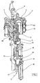
- Fig. 5 shows one opposite the representation in Fig. 1 modified representation of the blowing station (3) in a perspective view from the front.
- the stretch rod (11) is held by a stretch rod carrier (41).
- Fig. 5 also shows the arrangement of a pneumatic block (46) for blowing pressure supply to the blowing station (3).
- the pneumatic block (42) is equipped with high-pressure valves (43), which can be connected via connections (44) to one or more pressure supplies. After blow-molding of the containers (2), blown air to be discharged into an environment is first fed via the pneumatic block (42) to a silencer (45).
- FIG. 2 A typical implementation of the blowing process can be most easily based on Fig. 2 be illustrated.
- Fig. 5 also illustrates that the stretch rod carrier (41) is connected to a coupling element (46), which is at least partially behind a cover (47) out.
- the coupling element (46) is made using a in Fig. 5 unrecognizable threaded rod (48) by a servo motor (49) positionable. The arrangement of the threaded rod (48) will be described below with reference to Fig. 6 further explained.
- Fig. 6 shows a longitudinal section through the arrangement according to Fig. 5 , Laterally on the pneumatic block (42), a cam roller (50) can be seen, which serves for a mechanical positioning of the pneumatic block (42).
- the coupling element (46) is designed in the illustrated embodiment as a threaded bushing which engages with an internal thread in an external thread of the threaded rod (48).
- the coupling element (46) extends with connecting limbs partially laterally adjacent to the cover (47) and is thereby connected to the stretch rod carrier (41).
- the cover (47) shields the stretch rod (11) from the threaded rod (48), so that contamination of the stretch rod (11), for example, by the threaded rod (48) outgoing grease or oil particles is avoided.
- a threaded spindle can be used.
- the threaded rod (48) is connected via a coupling (51) to a motor shaft (52) of the servomotor (49).
- the motor shaft (52) and the threaded rod (48) extend along a common longitudinal axis, so that the threaded rod (48) is arranged as an extension of the motor shaft (52).
- a gearless connection of the motor shaft (52) with the threaded rod (48) is supported.
- a pneumatic valve (53) is arranged, optionally through the stretching rod (11) to guide a gaseous medium in the direction of the preform (1) or the container (2) or to discharge in the opposite direction. This may be, for example, blown air or cooling air.
- each of the servomotors (49) is equipped with a controller arranged immediately adjacent to the respective servomotor (49).
- An external specification of control values is carried out using a bus system which connects the control unit arranged on the blowing wheel (25) to a stationary main control.
- the on the blowing wheel (25) arranged power supply for the individual servomotors (49) can be connected via a slip ring coupling with a stationary power source.
- the threaded rod (48) is operated at the same speed as the motor shaft (52).
- the motor shaft (52) and the threaded rod (48) can be arranged with their respective longitudinal axes also transversely or obliquely to each other when a suitable non-positive connection is made via suitable coupling elements.
- the already mentioned control of the blowing process as a function of the condition data of the stretching operation can also be carried out, for example, in such a way that the connection of the pre-blowing pressure and / or the main blowing pressure is effected as a function of a specific positioning of the stretching rod (11).
- an associated blowgas valve is switched.
- each blow station (3) is assigned its own stretching system with stretch rod (11), threaded rod (48) and servomotor (49).
- stretch rod (11), threaded rod (48) and servomotor (49) In an arrangement of the blow molding stations (3) equipped with the stretching system according to the invention on a blowing wheel (25), it is possible, in particular, in a simple manner, the Performing the stretching process automatically to different production rates and thus different speeds of the blowing wheel (25) adapt. From a process point of view, it proves to be unfavorable to carry out the stretching process with different stretching speeds when the rotational speed of the blowing wheel (25) changes, because this would influence the material properties of the containers (2) produced. It is thus desirable, even at different speeds of the blowing wheel (25) to realize the stretching process with predetermined stretching speeds or stretching forces.
- stretching path time profiles, stretching force time profiles, stretching force stretching path profiles or other profiles for stretching parameters implement the stretching system according to the invention with high accuracy.
- the servomotor (49) it is possible to integrate a regulator used directly into the engine.
- a regulator used directly into the engine.
- the threaded rod (48) as an extension of the motor shaft (52) and also already described oblique or rectangular arrangement of the servomotor (49) relative to the threaded rod (48) with the interposition of a transmission or other coupling elements
- the assembly formed from the coupling element (46) and the threaded rod (48) in accordance with a ball screw spindle.
- the coupling element (46) in this case has an internal thread corresponding to a nut, which engages in an external thread of the threaded rod (48).
- a direct contact of the threads of the internal thread of the coupling element (46) and the external thread of the threaded rod (48) with each other can be avoided that in the threaded portion balls are arranged similar to a ball bearing.
- the internal thread and that external thread do not slide directly on each other and thereby generate sliding friction, but it is realized a much lower rolling friction.
- the balls are preferably arranged in the region of the internal thread of the coupling element (46).
- Fig. 7 shows a side view of a schematically illustrated blowing station (3), in which a stretch rod (11) via a coupling element (46) is connected to a schematically illustrated threaded rod (48) for positioning.
- the stretch rod is partially retracted in the operating state shown in a blow mold (4).
- Fig. 7 also schematically shows a pneumatic block (42), which may be designed as a so-called connecting piston and for supplying compressed air into the interior of the to be blown Container (2) is provided in it.
- the pneumatic block (42) is connected via supply lines not shown to a Blasgasmakers and serves as relative to the blow mold (4) positioned arranged Blasgaszu entry.
- the positionability is required so that after inserting a preform (1) in the blow mold (4) by a lifting movement, a pressure-tight connection between the pneumatic block (42) and the blow mold (4) or between the pneumatic block (42) and the preform ( 1) or the container to be blown (2) can be produced.
- the pneumatic block (42) via a pivot joint (54) with a transverse lever (55) is connected.
- the transverse lever (55) is connected via a joint (56) to a longitudinal lever (57), which in turn is coupled via a joint (58) to a support structure (59) of the blowing station (3).
- the longitudinal lever (57) extends substantially with a lever longitudinal axis substantially parallel to a longitudinal axis of the threaded rod (48).
- the pneumatic block (42) is additionally articulated to a positioning rod (60).
- the articulated connection is preferably realized in the region of the joint (54).
- the positioning rod (60) is connected in the region of its extension facing away from the pneumatic block (42) via a joint (61) to an adjusting lever (62) which is pivotably coupled via a joint (63) to the support structure (59) of the blowing station (1) is.
- the adjusting lever (62) has a driving profile (64), which can be realized, for example, by a U-shaped design of the adjusting lever (62). But it can also be provided groove-like depressions or corresponding guide projections.
- the driving profile (64) is provided for a positive contact with a driver (65), which is arranged in the region of the coupling element (46).
- the driver (65) is designed as a cam roller and the driving profile (64) is provided as a curved path with a dimensioning adapted to the driver (65).
- the driving profile (64) is intended to equip the driving profile (64) with a substantially vertically downward pointing insertion opening (66) and a subsequent and extending with a slightly curved course cam track.
- Fig. 7 shown operating state of the pneumatic block (42) is lowered and sealed against the blow mold (4) or the preform (1) out.
- an expansion of the preform (1) to the container (2) can be effected by a compressed gas supply.
- the toggle lever formed from the transverse lever (55) and the longitudinal lever (57) is located in an over-center position and thereby fixes the pneumatic block (42) without further actuating or holding forces in the illustrated positioning.
- the stretch rod (11) is in Fig. 7 shown after an already made partial withdrawal from the blow mold (4).
- the driver (65) and the driving profile (64) are decoupled, so that positioning movements of the coupling element (46) or connected to this stretch rod (11) cause no movement of the pneumatic block (42).
- Fig. 8 shows an embodiment in which the stretching rod (11) using the coupling element (46) by an associated rotational movement of the threaded rod (48) is already completely removed from the region of the blow mold (4).
Landscapes
- Engineering & Computer Science (AREA)
- Manufacturing & Machinery (AREA)
- Mechanical Engineering (AREA)
- Blow-Moulding Or Thermoforming Of Plastics Or The Like (AREA)
Claims (22)
- Procédé de moulage par soufflage de récipients (2) dans le cadre duquel une préforme (1) en un matériau thermoplastique, après un conditionnement thermique, est étirée par une barre d'étirage (11) à l'intérieur d'un moule de soufflage (4) et, sous l'action d'une pression de soufflage, transformée en un récipient (2), et dans le cadre duquel un positionnement défini de la barre d'étirage (11) est obtenu par la mise en oeuvre d'un entraînement de barre d'étirage, et dans le cadre duquel la pression de soufflage est produite à l'aide d'au moins une alimentation en gaz de soufflage positionnable, l'entraînement de barre d'étirage étant, temporairement au moins, couplé mécaniquement à l'alimentation en gaz de soufflage positionnable de façon à effectuer un mouvement commun, caractérisé en ce que le couplage mécanique entre l'entraînement de la barre d'étirage et l'alimentation en gaz de soufflage positionnable est réalisé au moyen d'un entraîneur (65) et d'un profil d'entraînement (64).
- Procédé selon la revendication 1, caractérisée en ce que la barre d'étirage (11) est couplée à une commande définissant une course de la barre d'étirage conformément à un profil de mouvement.
- Procédé selon la revendication 1 ou 2, caractérisée en ce qu'une course de positionnement de la barre d'étirage (11) est subdivisée en deux sections, une première section correspondant à un positionnement commun avec l'alimentation en gaz de soufflage et une seconde section exclusivement affectée au positionnement de la barre d'étirage (11).
- Procédé selon l'une des revendications 1 à 3, caractérisé en ce que la barre d'étirage (11) est positionnée par une tige filetée (48).
- Procédé selon l'une des revendications 1 à 3, caractérisé en ce que la barre d'étirage (11) est positionnée par une commande à came.
- Procédé selon l'une des revendications 1 à 3, caractérisé en ce que la barre d'étirage (11) est positionnée par un entraînement pneumatique.
- Procédé selon l'une des revendications 1 à 6, caractérisé en ce que l'alimentation en gaz de soufflage positionnable, une fois positionnée selon un agencement orienté vers le moule de soufflage (4), est fixée par un levier à genouillère.
- Procédé selon l'une des revendications 1 à 6, caractérisé en ce que l'alimentation en gaz de soufflage positionnable, une fois positionnée selon un agencement opposé au moule de soufflage (4), est fixée par un levier à genouillère.
- Procédé selon l'une des revendications 1 à 8, caractérisé en ce qu'une course de positionnement de la barre d'étirage (11) est stabilisée par une glissière.
- Procédé selon l'une des revendications 1 à 9, caractérisé en ce que l'entraîneur (65) s'engage dans le profil d'entraînement (64) exclusivement pendant une partie de sa course.
- Procédé selon l'une des revendications 1 à 10, caractérisé en ce que le profil d'entraînement (64), par un agencement dans la zone d'un levier de commande (62) pivotant, transforme un mouvement de l'entraîneur (65) en un mouvement de l'alimentation en gaz de soufflage positionnable.
- Dispositif de moulage par soufflage de récipients (2) en un matériau thermoplastique présentant au moins une station de soufflage (3) munie d'un moule de soufflage (4) et doté d'un dispositif d'étirage dans la zone duquel est agencée une barre d'étirage (11) qui agit sur une préforme (1) pouvant être placée dans le moule de soufflage (4), et dont la barre d'étirage (11) est couplée à un entraînement de barre d'étirage et la station de soufflage (3) présente une alimentation en gaz de soufflage positionnable, l'entraînement de barre d'étirage étant, le long d'une partie au moins d'une course de positionnement, couplé mécaniquement avec l'alimentation en gaz de soufflage positionnable, caractérisé en ce que l'alimentation en gaz de soufflage positionnable et l'entraînement de barre d'étirage sont couplés par un entraîneur (65) qui s'engage dans un profil d'entraînement (64).
- Dispositif selon la revendication 12, caractérisée en ce que la barre d'étirage (11) est couplée à un entraînement réglable en vue de réaliser une course conforme à un profil de mouvement défini.
- Dispositif selon la revendication 12 ou 13, caractérisé en ce que une course de positionnement de la barre d'étirage (11) est subdivisée en une première et une seconde section, la barre d'étirage (11) étant, dans une première section, couplée mécaniquement à l'alimentation en gaz de soufflage positionnable et en étant découplée dans la seconde section.
- Dispositif selon l'une des revendications 12 à 14, caractérisé en ce que l'entraînement de barre d'étirage présente une tige filetée (48) logée de façon à en permettre la rotation.
- Dispositif selon l'une des revendications 12 à 14, caractérisé en ce que l'entraînement de barre d'étirage présente une commande à came.
- Dispositif selon l'une des revendications 12 à 14, caractérisé en ce que l'entraînement de barre d'étirage présente un entraînement pneumatique.
- Dispositif selon l'une des revendications 12 à 17, caractérisé en ce que l'alimentation en gaz de soufflage positionnable est munie d'un levier à genouillère pour fixer un positionnement en une position orientée vers le moule de soufflage (4).
- Dispositif selon l'une des revendications 12 à 18, caractérisé en ce que l'alimentation en gaz de soufflage positionnable est munie d'un levier à genouillère pour fixer un positionnement en une position opposée au moule de soufflage (4).
- Dispositif selon l'une des revendications 12 à 19, caractérisé en ce que le système d'étirage présente une glissière pour coulisseau.
- Dispositif selon l'une des revendications 12 à 20, caractérisé en ce que le profil d'entraînement (64) a une longueur inférieure à l'étendue d'une course de positionnement de l'entraîneur (65).
- Dispositif selon l'une des revendications 12 à 21, caractérisé en ce que le profil d'entraînement (64) est agencé dans la zone d'un levier de commande (62) logé de façon à pouvoir pivoter.
Applications Claiming Priority (2)
| Application Number | Priority Date | Filing Date | Title |
|---|---|---|---|
| DE102009006508A DE102009006508A1 (de) | 2009-01-21 | 2009-01-21 | Verfahren und Vorrichtung zur Blasformung von Behältern |
| PCT/DE2010/000053 WO2010083810A2 (fr) | 2009-01-21 | 2010-01-18 | Procédé et dispositif de moulage par soufflage de contenants |
Publications (2)
| Publication Number | Publication Date |
|---|---|
| EP2382076A2 EP2382076A2 (fr) | 2011-11-02 |
| EP2382076B1 true EP2382076B1 (fr) | 2015-09-30 |
Family
ID=42263027
Family Applications (1)
| Application Number | Title | Priority Date | Filing Date |
|---|---|---|---|
| EP10707431.2A Active EP2382076B1 (fr) | 2009-01-21 | 2010-01-18 | Procédé et dispositif de moulage par soufflage de contenants |
Country Status (4)
| Country | Link |
|---|---|
| EP (1) | EP2382076B1 (fr) |
| CN (1) | CN102438807B (fr) |
| DE (2) | DE102009006508A1 (fr) |
| WO (1) | WO2010083810A2 (fr) |
Families Citing this family (15)
| Publication number | Priority date | Publication date | Assignee | Title |
|---|---|---|---|---|
| DE102011007280A1 (de) | 2011-04-13 | 2012-10-18 | Krones Aktiengesellschaft | Behälterbehandlungsmaschine und Verfahren zur Behälterbehandlung |
| DE102011079078A1 (de) * | 2011-07-13 | 2013-01-17 | Krones Ag | Einsternzuführung für Behandlungsmaschinen |
| DE102011079077A1 (de) | 2011-07-13 | 2013-01-17 | Krones Aktiengesellschaft | Blasmaschine für Kunststoffbehälter |
| DE202013009941U1 (de) | 2012-11-12 | 2013-11-20 | Khs Corpoplast Gmbh | Vorrichtung zur Blasformung von Behältern mit einer Antriebseinrichtung und mit gekoppelten Bewegungsabläufen |
| DE102013103543A1 (de) * | 2013-04-09 | 2014-10-09 | Krones Ag | Vorrichtung und Verfahren zum Umformen von Kunststoffvorformlingen zu Kunststoffbehältnissen |
| DE102013108789A1 (de) | 2013-08-14 | 2015-02-19 | Krones Ag | Blasformmaschine mit kontrollierter Reckstangen- und Blasdüsenbewegung |
| DE102014005183A1 (de) | 2014-04-03 | 2015-10-22 | Khs Corpoplast Gmbh | Vorrichtung zur Blasformung von Behältern |
| FR3024071B1 (fr) | 2014-07-25 | 2016-08-19 | Sidel Participations | Procede de controle d'un procede de soufflage de recipients en matiere plastique |
| CN107438508B (zh) | 2015-04-30 | 2019-08-20 | Khs科波普拉斯特有限责任公司 | 用于吹塑成型容器的设备 |
| FR3063926B1 (fr) * | 2017-03-17 | 2019-04-12 | Sidel Participations | Procede de reglage automatique de la course d'une tige d'etirage d'un dispositif de formage de corps creux |
| DE102017008446A1 (de) | 2017-09-08 | 2019-03-14 | Khs Corpoplast Gmbh | Verfahren, Vorrichtung, Arbeitsrad und Umformstation für die Herstellung von gefüllten Behältern aus temperaturkonditionierten Vorformlingen |
| CN113825618B (zh) * | 2019-04-03 | 2023-11-17 | 日精Asb机械株式会社 | 树脂容器制造装置及制造方法 |
| WO2021255502A1 (fr) * | 2020-06-18 | 2021-12-23 | Discma Ag | Système de formation et de remplissage de récipient à propriétés hydrophobes |
| DE102020125957A1 (de) | 2020-10-05 | 2022-04-07 | Krones Aktiengesellschaft | Vorrichtung und Verfahren zum Umformen von Kunststoffvorformlingen zu Kunststoffbehältnissen mit verbesserter Spülstangenanordnung |
| DE102024104932A1 (de) * | 2024-02-22 | 2025-08-28 | Khs Gmbh | Verfahren und Vorrichtung zum Herstellen von Behältern aus Vorformlingen aus einem thermoplastischen Material mit hoher Produktionsleistung |
Family Cites Families (10)
| Publication number | Priority date | Publication date | Assignee | Title |
|---|---|---|---|---|
| DE2352926A1 (de) | 1973-10-22 | 1975-04-24 | Heidenreich & Harbeck Gmbh | Verfahren und vorrichtung zum erwaermen eines werkstueckes aus kunststoff |
| JP2832263B2 (ja) | 1989-10-30 | 1998-12-09 | 株式会社青木固研究所 | 回転式射出延伸吹込成形機 |
| DE4212583A1 (de) | 1992-04-15 | 1993-10-21 | Krupp Corpoplast Masch | Vorrichtung zur Blasformung |
| DE4340291A1 (de) | 1993-11-26 | 1995-06-01 | Krupp Corpoplast Masch | Mehrfachnutzung von Blasluft |
| DE19906438A1 (de) | 1999-02-16 | 2000-08-17 | Krupp Corpoplast Masch | Verfahren und Vorrichtung zur Übergabe von Behältern |
| FR2814392B1 (fr) | 2000-09-25 | 2002-12-20 | Sidel Sa | Machine d'etirage-soufflage comportant une commande perfectionnee de la tige d'etirage |
| DE102005034846A1 (de) * | 2005-07-26 | 2007-02-01 | Sig Technology Ag | Verfahren und Vorrichtung zur Positionierung eines Bauelementes |
| FR2889671B1 (fr) * | 2005-08-12 | 2009-08-07 | Sidel Sas | Poste de soufflage pour installation d'etirage soufflage de recipients et installation comportant un tel ensemble |
| JP5244823B2 (ja) | 2007-02-15 | 2013-07-24 | カーハーエス コーポプラスト ゲーエムベーハー | 容器をブロー成形するための方法および装置 |
| DE102007008023A1 (de) * | 2007-02-15 | 2008-08-21 | Sig Technology Ag | Verfahren und Vorrichtung zur Blasformung von Behältern |
-
2009
- 2009-01-21 DE DE102009006508A patent/DE102009006508A1/de not_active Withdrawn
-
2010
- 2010-01-18 DE DE202010018363.4U patent/DE202010018363U1/de not_active Expired - Lifetime
- 2010-01-18 WO PCT/DE2010/000053 patent/WO2010083810A2/fr not_active Ceased
- 2010-01-18 CN CN201080008867.1A patent/CN102438807B/zh active Active
- 2010-01-18 EP EP10707431.2A patent/EP2382076B1/fr active Active
Also Published As
| Publication number | Publication date |
|---|---|
| DE202010018363U1 (de) | 2015-12-09 |
| CN102438807B (zh) | 2015-01-21 |
| CN102438807A (zh) | 2012-05-02 |
| DE102009006508A1 (de) | 2010-07-22 |
| WO2010083810A3 (fr) | 2010-10-07 |
| EP2382076A2 (fr) | 2011-11-02 |
| WO2010083810A2 (fr) | 2010-07-29 |
Similar Documents
| Publication | Publication Date | Title |
|---|---|---|
| EP2382076B1 (fr) | Procédé et dispositif de moulage par soufflage de contenants | |
| EP2117806B1 (fr) | Procédé et dispositif de soufflage de conteneurs avec l'utilisation d'un servomoteur pour entraîner la tige d'étirage | |
| EP2139665B1 (fr) | Procédé et dispositif de moulage par soufflage de récipients | |
| EP2144742B1 (fr) | Dispositif de moulage par soufflage de récipients | |
| DE102007008023A1 (de) | Verfahren und Vorrichtung zur Blasformung von Behältern | |
| EP2429795B1 (fr) | Procédé et dispositif pour le moulage par soufflage et le remplissage de récipients | |
| EP2618986B1 (fr) | Procédé et dispositif de moulage par soufflage de récipients | |
| EP2917019B1 (fr) | Procédé et dispositif de moulage par soufflage de récipients comprenant un dispositif d'entraînement et des séquences de mouvements couplées | |
| EP2419256A1 (fr) | Procédé et dispositif de moulage par soufflage de contenants | |
| EP1868767B1 (fr) | Procede et dispositif de positionnement d'un composant | |
| EP1910056B1 (fr) | Procede et dispositif de positionnement d'un composant | |
| EP1350612B1 (fr) | Appareil pour le transport de préformes / paraisons avec des pinces controlables séparement et fixées radialement sur une disque tournante / rotative | |
| EP2694270B1 (fr) | Dispositif pour le moulage de recipients par soufflage | |
| EP1574318B1 (fr) | Procédé et appareil de formage de récipients par soufflage | |
| EP2353842B1 (fr) | Machine d'étirage-soufflage et procédé d'étirage-soufflage avec compensation de contre-pression | |
| DE102005045942A1 (de) | Verfahren und Vorrichtung zur Blasformung von Behältern | |
| EP1473139B1 (fr) | Procédé et appareil de formage de récipients par soufflage | |
| DE19807582A1 (de) | Verfahren und Vorrichtung zur Blasformung von Behältern | |
| EP2237941B1 (fr) | Procédé et dispositif de formage par soufflage de récipients | |
| EP2768654B1 (fr) | Dispositif de retenue de pièces |
Legal Events
| Date | Code | Title | Description |
|---|---|---|---|
| PUAI | Public reference made under article 153(3) epc to a published international application that has entered the european phase |
Free format text: ORIGINAL CODE: 0009012 |
|
| 17P | Request for examination filed |
Effective date: 20110723 |
|
| AK | Designated contracting states |
Kind code of ref document: A2 Designated state(s): AT BE BG CH CY CZ DE DK EE ES FI FR GB GR HR HU IE IS IT LI LT LU LV MC MK MT NL NO PL PT RO SE SI SK SM TR |
|
| DAX | Request for extension of the european patent (deleted) | ||
| 17Q | First examination report despatched |
Effective date: 20130402 |
|
| GRAP | Despatch of communication of intention to grant a patent |
Free format text: ORIGINAL CODE: EPIDOSNIGR1 |
|
| RIC1 | Information provided on ipc code assigned before grant |
Ipc: B29C 49/42 20060101ALI20150513BHEP Ipc: B29C 49/06 20060101ALI20150513BHEP Ipc: B29C 49/64 20060101ALI20150513BHEP Ipc: B29C 49/78 20060101ALI20150513BHEP Ipc: B29C 49/36 20060101ALI20150513BHEP Ipc: B29K 67/00 20060101ALI20150513BHEP Ipc: B29C 49/16 20060101ALI20150513BHEP Ipc: B29C 49/12 20060101AFI20150513BHEP Ipc: B29K 23/00 20060101ALI20150513BHEP |
|
| INTG | Intention to grant announced |
Effective date: 20150528 |
|
| GRAS | Grant fee paid |
Free format text: ORIGINAL CODE: EPIDOSNIGR3 |
|
| GRAA | (expected) grant |
Free format text: ORIGINAL CODE: 0009210 |
|
| AK | Designated contracting states |
Kind code of ref document: B1 Designated state(s): AT BE BG CH CY CZ DE DK EE ES FI FR GB GR HR HU IE IS IT LI LT LU LV MC MK MT NL NO PL PT RO SE SI SK SM TR |
|
| REG | Reference to a national code |
Ref country code: CH Ref legal event code: EP Ref country code: GB Ref legal event code: FG4D Free format text: NOT ENGLISH |
|
| REG | Reference to a national code |
Ref country code: AT Ref legal event code: REF Ref document number: 752126 Country of ref document: AT Kind code of ref document: T Effective date: 20151015 |
|
| REG | Reference to a national code |
Ref country code: IE Ref legal event code: FG4D Free format text: LANGUAGE OF EP DOCUMENT: GERMAN |
|
| REG | Reference to a national code |
Ref country code: DE Ref legal event code: R096 Ref document number: 502010010376 Country of ref document: DE |
|
| REG | Reference to a national code |
Ref country code: FR Ref legal event code: PLFP Year of fee payment: 7 |
|
| PG25 | Lapsed in a contracting state [announced via postgrant information from national office to epo] |
Ref country code: GR Free format text: LAPSE BECAUSE OF FAILURE TO SUBMIT A TRANSLATION OF THE DESCRIPTION OR TO PAY THE FEE WITHIN THE PRESCRIBED TIME-LIMIT Effective date: 20151231 Ref country code: NO Free format text: LAPSE BECAUSE OF FAILURE TO SUBMIT A TRANSLATION OF THE DESCRIPTION OR TO PAY THE FEE WITHIN THE PRESCRIBED TIME-LIMIT Effective date: 20151230 Ref country code: LV Free format text: LAPSE BECAUSE OF FAILURE TO SUBMIT A TRANSLATION OF THE DESCRIPTION OR TO PAY THE FEE WITHIN THE PRESCRIBED TIME-LIMIT Effective date: 20150930 Ref country code: LT Free format text: LAPSE BECAUSE OF FAILURE TO SUBMIT A TRANSLATION OF THE DESCRIPTION OR TO PAY THE FEE WITHIN THE PRESCRIBED TIME-LIMIT Effective date: 20150930 Ref country code: FI Free format text: LAPSE BECAUSE OF FAILURE TO SUBMIT A TRANSLATION OF THE DESCRIPTION OR TO PAY THE FEE WITHIN THE PRESCRIBED TIME-LIMIT Effective date: 20150930 |
|
| REG | Reference to a national code |
Ref country code: NL Ref legal event code: MP Effective date: 20150930 |
|
| REG | Reference to a national code |
Ref country code: LT Ref legal event code: MG4D |
|
| PG25 | Lapsed in a contracting state [announced via postgrant information from national office to epo] |
Ref country code: HR Free format text: LAPSE BECAUSE OF FAILURE TO SUBMIT A TRANSLATION OF THE DESCRIPTION OR TO PAY THE FEE WITHIN THE PRESCRIBED TIME-LIMIT Effective date: 20150930 Ref country code: SE Free format text: LAPSE BECAUSE OF FAILURE TO SUBMIT A TRANSLATION OF THE DESCRIPTION OR TO PAY THE FEE WITHIN THE PRESCRIBED TIME-LIMIT Effective date: 20150930 |
|
| PG25 | Lapsed in a contracting state [announced via postgrant information from national office to epo] |
Ref country code: SK Free format text: LAPSE BECAUSE OF FAILURE TO SUBMIT A TRANSLATION OF THE DESCRIPTION OR TO PAY THE FEE WITHIN THE PRESCRIBED TIME-LIMIT Effective date: 20150930 Ref country code: EE Free format text: LAPSE BECAUSE OF FAILURE TO SUBMIT A TRANSLATION OF THE DESCRIPTION OR TO PAY THE FEE WITHIN THE PRESCRIBED TIME-LIMIT Effective date: 20150930 Ref country code: ES Free format text: LAPSE BECAUSE OF FAILURE TO SUBMIT A TRANSLATION OF THE DESCRIPTION OR TO PAY THE FEE WITHIN THE PRESCRIBED TIME-LIMIT Effective date: 20150930 Ref country code: IS Free format text: LAPSE BECAUSE OF FAILURE TO SUBMIT A TRANSLATION OF THE DESCRIPTION OR TO PAY THE FEE WITHIN THE PRESCRIBED TIME-LIMIT Effective date: 20160130 Ref country code: CZ Free format text: LAPSE BECAUSE OF FAILURE TO SUBMIT A TRANSLATION OF THE DESCRIPTION OR TO PAY THE FEE WITHIN THE PRESCRIBED TIME-LIMIT Effective date: 20150930 Ref country code: NL Free format text: LAPSE BECAUSE OF FAILURE TO SUBMIT A TRANSLATION OF THE DESCRIPTION OR TO PAY THE FEE WITHIN THE PRESCRIBED TIME-LIMIT Effective date: 20150930 |
|
| PG25 | Lapsed in a contracting state [announced via postgrant information from national office to epo] |
Ref country code: PL Free format text: LAPSE BECAUSE OF FAILURE TO SUBMIT A TRANSLATION OF THE DESCRIPTION OR TO PAY THE FEE WITHIN THE PRESCRIBED TIME-LIMIT Effective date: 20150930 Ref country code: RO Free format text: LAPSE BECAUSE OF FAILURE TO SUBMIT A TRANSLATION OF THE DESCRIPTION OR TO PAY THE FEE WITHIN THE PRESCRIBED TIME-LIMIT Effective date: 20150930 Ref country code: PT Free format text: LAPSE BECAUSE OF FAILURE TO SUBMIT A TRANSLATION OF THE DESCRIPTION OR TO PAY THE FEE WITHIN THE PRESCRIBED TIME-LIMIT Effective date: 20160201 Ref country code: BE Free format text: LAPSE BECAUSE OF NON-PAYMENT OF DUE FEES Effective date: 20160131 |
|
| REG | Reference to a national code |
Ref country code: DE Ref legal event code: R097 Ref document number: 502010010376 Country of ref document: DE |
|
| PLBE | No opposition filed within time limit |
Free format text: ORIGINAL CODE: 0009261 |
|
| STAA | Information on the status of an ep patent application or granted ep patent |
Free format text: STATUS: NO OPPOSITION FILED WITHIN TIME LIMIT |
|
| PG25 | Lapsed in a contracting state [announced via postgrant information from national office to epo] |
Ref country code: DK Free format text: LAPSE BECAUSE OF FAILURE TO SUBMIT A TRANSLATION OF THE DESCRIPTION OR TO PAY THE FEE WITHIN THE PRESCRIBED TIME-LIMIT Effective date: 20150930 Ref country code: LU Free format text: LAPSE BECAUSE OF FAILURE TO SUBMIT A TRANSLATION OF THE DESCRIPTION OR TO PAY THE FEE WITHIN THE PRESCRIBED TIME-LIMIT Effective date: 20160118 |
|
| REG | Reference to a national code |
Ref country code: CH Ref legal event code: PL |
|
| 26N | No opposition filed |
Effective date: 20160701 |
|
| GBPC | Gb: european patent ceased through non-payment of renewal fee |
Effective date: 20160118 |
|
| PG25 | Lapsed in a contracting state [announced via postgrant information from national office to epo] |
Ref country code: MC Free format text: LAPSE BECAUSE OF FAILURE TO SUBMIT A TRANSLATION OF THE DESCRIPTION OR TO PAY THE FEE WITHIN THE PRESCRIBED TIME-LIMIT Effective date: 20150930 |
|
| PG25 | Lapsed in a contracting state [announced via postgrant information from national office to epo] |
Ref country code: LI Free format text: LAPSE BECAUSE OF NON-PAYMENT OF DUE FEES Effective date: 20160131 Ref country code: CH Free format text: LAPSE BECAUSE OF NON-PAYMENT OF DUE FEES Effective date: 20160131 Ref country code: GB Free format text: LAPSE BECAUSE OF NON-PAYMENT OF DUE FEES Effective date: 20160118 |
|
| REG | Reference to a national code |
Ref country code: IE Ref legal event code: MM4A |
|
| PG25 | Lapsed in a contracting state [announced via postgrant information from national office to epo] |
Ref country code: SI Free format text: LAPSE BECAUSE OF FAILURE TO SUBMIT A TRANSLATION OF THE DESCRIPTION OR TO PAY THE FEE WITHIN THE PRESCRIBED TIME-LIMIT Effective date: 20150930 |
|
| REG | Reference to a national code |
Ref country code: FR Ref legal event code: PLFP Year of fee payment: 8 |
|
| PG25 | Lapsed in a contracting state [announced via postgrant information from national office to epo] |
Ref country code: IE Free format text: LAPSE BECAUSE OF NON-PAYMENT OF DUE FEES Effective date: 20160118 |
|
| REG | Reference to a national code |
Ref country code: AT Ref legal event code: MM01 Ref document number: 752126 Country of ref document: AT Kind code of ref document: T Effective date: 20160118 |
|
| PG25 | Lapsed in a contracting state [announced via postgrant information from national office to epo] |
Ref country code: AT Free format text: LAPSE BECAUSE OF NON-PAYMENT OF DUE FEES Effective date: 20160118 |
|
| PG25 | Lapsed in a contracting state [announced via postgrant information from national office to epo] |
Ref country code: MT Free format text: LAPSE BECAUSE OF FAILURE TO SUBMIT A TRANSLATION OF THE DESCRIPTION OR TO PAY THE FEE WITHIN THE PRESCRIBED TIME-LIMIT Effective date: 20150930 |
|
| REG | Reference to a national code |
Ref country code: FR Ref legal event code: PLFP Year of fee payment: 9 |
|
| PG25 | Lapsed in a contracting state [announced via postgrant information from national office to epo] |
Ref country code: HU Free format text: LAPSE BECAUSE OF FAILURE TO SUBMIT A TRANSLATION OF THE DESCRIPTION OR TO PAY THE FEE WITHIN THE PRESCRIBED TIME-LIMIT; INVALID AB INITIO Effective date: 20100118 Ref country code: CY Free format text: LAPSE BECAUSE OF FAILURE TO SUBMIT A TRANSLATION OF THE DESCRIPTION OR TO PAY THE FEE WITHIN THE PRESCRIBED TIME-LIMIT Effective date: 20150930 Ref country code: SM Free format text: LAPSE BECAUSE OF FAILURE TO SUBMIT A TRANSLATION OF THE DESCRIPTION OR TO PAY THE FEE WITHIN THE PRESCRIBED TIME-LIMIT Effective date: 20150930 |
|
| PG25 | Lapsed in a contracting state [announced via postgrant information from national office to epo] |
Ref country code: TR Free format text: LAPSE BECAUSE OF FAILURE TO SUBMIT A TRANSLATION OF THE DESCRIPTION OR TO PAY THE FEE WITHIN THE PRESCRIBED TIME-LIMIT Effective date: 20150930 Ref country code: MK Free format text: LAPSE BECAUSE OF FAILURE TO SUBMIT A TRANSLATION OF THE DESCRIPTION OR TO PAY THE FEE WITHIN THE PRESCRIBED TIME-LIMIT Effective date: 20150930 |
|
| PG25 | Lapsed in a contracting state [announced via postgrant information from national office to epo] |
Ref country code: BG Free format text: LAPSE BECAUSE OF FAILURE TO SUBMIT A TRANSLATION OF THE DESCRIPTION OR TO PAY THE FEE WITHIN THE PRESCRIBED TIME-LIMIT Effective date: 20150930 |
|
| REG | Reference to a national code |
Ref country code: DE Ref legal event code: R082 Ref document number: 502010010376 Country of ref document: DE Representative=s name: EISENFUEHR SPEISER PATENTANWAELTE RECHTSANWAEL, DE |
|
| REG | Reference to a national code |
Ref country code: DE Ref legal event code: R082 Ref document number: 502010010376 Country of ref document: DE Representative=s name: EISENFUEHR SPEISER PATENTANWAELTE RECHTSANWAEL, DE Ref country code: DE Ref legal event code: R081 Ref document number: 502010010376 Country of ref document: DE Owner name: KHS GMBH, DE Free format text: FORMER OWNER: KHS CORPOPLAST GMBH, 22145 HAMBURG, DE Ref country code: DE Ref legal event code: R082 Ref document number: 502010010376 Country of ref document: DE |
|
| REG | Reference to a national code |
Ref country code: DE Ref legal event code: R082 Ref document number: 502010010376 Country of ref document: DE Representative=s name: EISENFUEHR SPEISER PATENTANWAELTE RECHTSANWAEL, DE |
|
| P01 | Opt-out of the competence of the unified patent court (upc) registered |
Free format text: CASE NUMBER: UPC_APP_0014580_2382076/2025 Effective date: 20251125 |
|
| PGFP | Annual fee paid to national office [announced via postgrant information from national office to epo] |
Ref country code: DE Payment date: 20260121 Year of fee payment: 17 |
|
| PGFP | Annual fee paid to national office [announced via postgrant information from national office to epo] |
Ref country code: IT Payment date: 20260126 Year of fee payment: 17 |
|
| PGFP | Annual fee paid to national office [announced via postgrant information from national office to epo] |
Ref country code: FR Payment date: 20260123 Year of fee payment: 17 |