EP2382096B1 - Impression avec recouvrement - Google Patents
Impression avec recouvrement Download PDFInfo
- Publication number
- EP2382096B1 EP2382096B1 EP09839394.5A EP09839394A EP2382096B1 EP 2382096 B1 EP2382096 B1 EP 2382096B1 EP 09839394 A EP09839394 A EP 09839394A EP 2382096 B1 EP2382096 B1 EP 2382096B1
- Authority
- EP
- European Patent Office
- Prior art keywords
- ink
- color
- region
- die
- media
- Prior art date
- Legal status (The legal status is an assumption and is not a legal conclusion. Google has not performed a legal analysis and makes no representation as to the accuracy of the status listed.)
- Active
Links
- 238000007639 printing Methods 0.000 title description 8
- 239000003086 colorant Substances 0.000 claims description 23
- 238000000034 method Methods 0.000 claims description 20
- 239000000976 ink Substances 0.000 description 87
- 238000003384 imaging method Methods 0.000 description 9
- 238000003491 array Methods 0.000 description 2
- 238000006243 chemical reaction Methods 0.000 description 2
- 239000007788 liquid Substances 0.000 description 2
- 230000003466 anti-cipated effect Effects 0.000 description 1
- 238000004891 communication Methods 0.000 description 1
- 230000003750 conditioning effect Effects 0.000 description 1
- 238000011161 development Methods 0.000 description 1
- 230000018109 developmental process Effects 0.000 description 1
- 230000005484 gravity Effects 0.000 description 1
- 238000007641 inkjet printing Methods 0.000 description 1
- 238000012986 modification Methods 0.000 description 1
- 230000004048 modification Effects 0.000 description 1
- 230000003287 optical effect Effects 0.000 description 1
- 230000007704 transition Effects 0.000 description 1
- 230000007723 transport mechanism Effects 0.000 description 1
Images


Classifications
-
- B—PERFORMING OPERATIONS; TRANSPORTING
- B41—PRINTING; LINING MACHINES; TYPEWRITERS; STAMPS
- B41J—TYPEWRITERS; SELECTIVE PRINTING MECHANISMS, i.e. MECHANISMS PRINTING OTHERWISE THAN FROM A FORME; CORRECTION OF TYPOGRAPHICAL ERRORS
- B41J2/00—Typewriters or selective printing mechanisms characterised by the printing or marking process for which they are designed
- B41J2/005—Typewriters or selective printing mechanisms characterised by the printing or marking process for which they are designed characterised by bringing liquid or particles selectively into contact with a printing material
- B41J2/01—Ink jet
- B41J2/135—Nozzles
- B41J2/145—Arrangement thereof
- B41J2/155—Arrangement thereof for line printing
-
- B—PERFORMING OPERATIONS; TRANSPORTING
- B41—PRINTING; LINING MACHINES; TYPEWRITERS; STAMPS
- B41J—TYPEWRITERS; SELECTIVE PRINTING MECHANISMS, i.e. MECHANISMS PRINTING OTHERWISE THAN FROM A FORME; CORRECTION OF TYPOGRAPHICAL ERRORS
- B41J2/00—Typewriters or selective printing mechanisms characterised by the printing or marking process for which they are designed
- B41J2/005—Typewriters or selective printing mechanisms characterised by the printing or marking process for which they are designed characterised by bringing liquid or particles selectively into contact with a printing material
- B41J2/01—Ink jet
- B41J2/21—Ink jet for multi-colour printing
- B41J2/2132—Print quality control characterised by dot disposition, e.g. for reducing white stripes or banding
-
- B—PERFORMING OPERATIONS; TRANSPORTING
- B41—PRINTING; LINING MACHINES; TYPEWRITERS; STAMPS
- B41J—TYPEWRITERS; SELECTIVE PRINTING MECHANISMS, i.e. MECHANISMS PRINTING OTHERWISE THAN FROM A FORME; CORRECTION OF TYPOGRAPHICAL ERRORS
- B41J2/00—Typewriters or selective printing mechanisms characterised by the printing or marking process for which they are designed
- B41J2/005—Typewriters or selective printing mechanisms characterised by the printing or marking process for which they are designed characterised by bringing liquid or particles selectively into contact with a printing material
- B41J2/01—Ink jet
- B41J2/21—Ink jet for multi-colour printing
- B41J2/2132—Print quality control characterised by dot disposition, e.g. for reducing white stripes or banding
- B41J2/2146—Print quality control characterised by dot disposition, e.g. for reducing white stripes or banding for line print heads
Definitions
- Page-wide array printing uses a plurality of fixed (i.e., stationary), ink jetting dies to simultaneously form images across a width-wise aspect of a moving sheet media such as paper, etc.
- each of the dies includes numerous rows of nozzles configured to controllably discharge ink, wherein each row of nozzles is used to apply a particular color.
- each die typically prints over a fraction of the overall width of the receiving media.
- a transition or "overlap print zone" exists where the respective printing ranges of adjacent dies coincide.
- one or more colored inks are applied to media at respective partial intensities by a first die, and then additional inks of the same color or colors are applied by a second die in order to complete the desired imaging within any particular overlap print zone.
- This partial-on-partial ink application technique is referred to as "shingling". Shingling is performed in the interest of color consistency within the overall image, and to avoid streaks, bars, lines, step changes or other undesirable artifacts that can occur within the overlap print zone.
- US 2005/128248 A1 discloses an ink-jet head including head chips.
- Each of the head chips includes discharge ports arranged at least along first and second rows having end portions.
- the first and second head chips adjoin each other such that the first and second rows of ports of the first head chip are staggered relative to the first and second rows of ports for the second head chip at their end portions.
- a first discharge port of the first head chip which is configured to discharge a first color ink
- a second discharge port of the second head chip which is configured to discharge a second color ink.
- a second discharge port of the first head chip which is configured to discharge the second color ink, does not overlap with a first discharge port of the first head chip, which is configured to discharge the first color ink.
- US 2007/0165056 A1 discloses a print head comprising overlapping chips, each chip having a plurality of recording elements.
- a determination unit determines whether an end of an image to be recorded is included in the overlap portion and, if so, one chip of the chips overlapping at the overlap portion is used only.
- the invention provides a method according to claim 1.
- FIG. 1 depicts a printer 100 according to one embodiment.
- the printer 100 is illustrative and non-limiting with respect to the present teachings. Thus, any practical number of other embodiments of printer, web printing system, etc., can be defined and used in accordance with the present teachings.
- the printer 100 includes a controller 102.
- the controller 102 is illustrative and non-limiting in nature. Other embodiments of controller can also be defined and used.
- the controller 102 is configured to control one or more normal operations of the printer 100 in accordance with the present teachings.
- the controller 102 includes a processor 104 configured to execute corresponding program code. Any suitable embodiment of microprocessor, microcontroller or other similar device (or plurality of devices) can be used to define processor 104.
- the controller 102 also includes computer-readable storage media (storage media) 106.
- the storage media 106 includes a program code (not shown) configured for execution by the processor 104.
- the storage media 106 can be defined by any one or more suitable forms of storage. Non-limiting examples of storage media 106 include solid-state memory, non-volatile memory, optical storage media (CD-ROM, etc.), magnetic storage media (hard drive, floppy disk, etc.), RAM, ROM, programmable read-only memory, etc. Other forms of computer-readable storage media 106 can also be used.
- the controller 102 further includes electronic circuitry 108.
- the circuitry 108 can be defined by any suitable circuitry as needed and/or desired for normal operation of the controller 102.
- Non-limiting examples of circuitry 108 include power conditioning circuitry, analog-to-digital conversion (ADC) and/or digital-to-analog conversion (DAC), digital logic, state machine logic, application-specific integrated circuitry, etc.
- a controller (not shown) is provided that omits the processor 104 and/or the storage media 106, and operates solely by way of dedicated purpose electronic circuitry. It is to be understood that any suitable electronic means can be used to provide for control of the printer 102 in accordance with the present teachings.
- the printer 100 also includes a page-wide print array (array) 110.
- the array 110 includes a plurality of print dies, of which two illustrative dies 112 and 114 are depicted in FIG. 1 . Dies 112 and 114 are understood to be arranged in staggered adjacency to one another as will be described in greater detail hereinafter. Each of dies 112 and 114 are further understood to be members of two respective rows of dies extending into the page of FIG. 1 . Thus, other dies (not shown) are assumed to be included in array 100 such that colored inks can be applied to the full printable width of a media 116.
- Array 110 is configured to operate in accordance with control signals provided by controller 102. Typical, normal operation of the page-wide print array 110 is described in further detail hereinafter.
- the printer 100 further includes other resources 118 as needed for normal operation.
- Non-limiting and illustrative examples of other resources 118 include one or more colored ink supplies, a power supply, input/output data communication circuitry, wireless resources, an operator interface, sheet media transport mechanisms, etc.
- printer 100 can include various resources as desired in accordance with the present teachings, and that further elaboration of other resources 118 is not required for purposes of understanding the present teachings.
- Illustrative and non-limiting operation of the printer 100 is as follows: Media 116, such as paper, is transported in the direction depicted and into operative (i.e., printable) proximity to the page-wide array 110. As such, the media 116 first passes under die 112 where one or more colored inks are applied so as to define imaging (i.e., text, symbols, indicia, photographic images, etc.) thereon. The media 116 then passes under die 114, wherein one or more colored inks are applied so as to complete the imaging to be formed. Controller 102 provides signals that control the application of colored inks by the dies 112 and 114.
- imaging i.e., text, symbols, indicia, photographic images, etc.
- imaging is presumed to be performed in accordance with an image data file (e.g., text document, photograph, etc.) provided to the printer 100 by an external entity (not shown) such as a computer, network server, or other device. It is further presumed for illustration that the printer 100 operates according to a four color scheme (e.g., black, cyan, magenta and yellow; etc.).
- an image data file e.g., text document, photograph, etc.
- an external entity not shown
- the printer 100 operates according to a four color scheme (e.g., black, cyan, magenta and yellow; etc.).
- An overlap print zone exists due to the staggered arrangement of the dies 112 and 114.
- the controller 102 operates so as to control the application of colored inks to the media 116 within the overlap print zone (as well as elsewhere).
- the controller 102 is configured to control operation of the page-wide print array 110 in accordance with a sequential application hierarchy of colors.
- Such hierarchies can be defined to include any practical number of colors and their order (i.e., ranking) of overlapping placement onto the media. Further elaboration on such sequential application hierarchies is provided hereinafter.
- the various colors used by the printer 100 are properly controlled according to a sequential application hierarchy resulting in proper hue and color saturation within the imaging formed on the media 116, while accommodating the partial-on-partial ink intensity shingling scheme used within the overlap print zones of the page-wide print array.
- FIG. 2A depicts a page-wide print array (array) 200 according to one embodiment.
- the array 200 is illustrative and non-limiting in nature. Other arrays (not shown) can also be defined and used in accordance with the present teachings.
- the array 200 includes a plurality of print dies (dies) 202, 204, 206 and 208.
- Each of the dies 202-208 includes a plurality of nozzles arranged in rows, wherein each row corresponds to a color of liquid ink to be applied.
- the dies 202-208 are each configured for operation in accordance with four colors of liquid ink.
- a different number of rows can be used within the respective dies.
- the number of nozzles within the rows can vary, as can the offset (pitch) between nozzles and/or die overlap from embodiment to embodiment.
- the dies 202-208 are arranged in staggered adjacency such that respective overlap print zones 210, 212 and 214 are defined.
- the array 200 is controlled in accordance with a shingling scheme so that proper hue and color saturation are achieved on the receiving media (e.g., paper, etc.) within the overlap print zones 210-214.
- shingling schemes employ respective sequential application hierarchies.
- the page-wide print array 200 is in plan view looking directly into the nozzles of the respective dies 202-208.
- the dies 202-208 are supported in a plane such that a print zone is defined extending across the width (or usable portion) of a media such as paper, etc.
- the array 200 includes a total of four dies 202-208 in the interest of simplicity, it is to be understood that other arrays can include any practical number of dies according to the present teachings.
- the array 200 is typically - but not necessarily - oriented such that ink is discharged downward with respect to gravity onto the receiving media.
- FIG. 2B depicts selected details of the page-wide print array (array) 200 as introduced above.
- the staggered arrangement of the dies 202 and 204 defines the overlap print zone 210.
- the dies 202 and 204 further include respective pluralities of ink discharge nozzles (nozzles) 220.
- Each of the nozzles 220 is individually addressable by a corresponding controller (e.g., 102) so as to apply a selective quantity of colored ink over a media during normal operation.
- a controller e.g. 102
- the phrases "over a media” and “over media” both refer to applying an ink or inks that is/are ultimately supported by the media, and direct contact may be with the media itself or with one or more other underlying color(s) of ink.
- any particular application of ink can be directly onto the media, directly onto previously applied ink or inks, or any combination of media and previously applied ink(s), in accordance with the phrases "over a media” and "over media”.
- nozzles 220 are depicted as squares in the interest of simplicity, it is to be understood that nozzles in accordance with the present teachings can be defined by any suitable cross-sectional form (e.g., circular, elliptical, etc.).
- the respective nozzles 220 of die 202 are arranged into four rows 222, 224, 226 and 228, respectively.
- the nozzles of row 222 are configured and coupled to resources as needed so as to discharge black ink.
- the nozzles of row 224 are configured to discharge cyan ink
- the nozzles of row 226 are configured to discharge magenta ink
- the nozzles of row 228 are configured to discharge yellow ink.
- other colors, numbers of colors, and/or their order within respective rows can be used.
- the respective nozzles 220 of die 204 are arranged into four rows 230, 232, 234 and 236, respectively.
- the corresponding order of colors of the rows 230-236 of die 204 are matched to those of rows 222-228 of die 202.
- the nozzles of rows 230, 232, 234 and 236 are configured and supplied so as to discharge black ink, cyan ink, magenta ink and yellow ink, respectively.
- a paper media is transported in the direction depicted in FIG. 2B .
- the order in which colored ink can be applied to the media is determined in accordance with the respective colors assigned to rows 222-228 of the die 202, with likewise color ordering of the rows 230-236 of die 204.
- colored inks can be applied to the media as black first, and then cyan, and then magenta, and then yellow. This order is followed in accord with the particular sequential application hierarchy being used. Again, other hierarchies can also be defined and used.
- imaging is to be performed within the overlap print zone 210 (and optionally elsewhere, as well). It is also assumed that cyan ink is to be applied over black ink in order to achieve a desired hue. It is further assumed, under the applicable sequential application hierarchy, that it is undesirable to apply any significant amount of black ink over cyan ink, magenta ink or yellow ink. In this case, appropriate individual control of the nozzles 220 of the dies 202 and 204 within the overlap print zone 210 will be performed to ensure that inks are applied in desired color order, onto media and/or previously applied ink(s), without applying a color of lesser hierarchical order over another color of greater hierarchical order. Controlled, hierarchical ink application within the overlap print zones is referred to herein as trapezoidal shingling due to the shape defined by the respectively used and unused nozzles 220 on a particular die.
- FIG. 3 depicts a plan view of an illustrative and non-limiting operation 300 in accordance with the present teachings.
- the operation 300 depicts just one of an essentially unlimited number of shingling operations that can be performed according to the present teachings. Thus, numerous other shingling operations performed in accordance with respective sequential application hierarchies of colors can also be performed within the scope of the present teachings.
- Operation 300 is performed using a first die 302 and a second die 304 disposed in staggered adjacency to each other such that an overlap print zone 306 is defined.
- Sheet media (i.e., paper) 308 is transported beneath and into operative proximity to the dies 302 and 304 in the direction indicated.
- cyan ink is first applied to the media 308 by way of a row of nozzles 310 of the first die 302.
- the nozzles of row 310 are individually controlled such that cyan ink is applied at full intensity within a region 312, while cyan ink is applied at less than full intensity (i.e., partial intensity) within a region 314. It is noted that some of the full-intensity application of cyan ink occurs within the overlap print zone 306, while all of the partial-intensity application of cyan ink occurs within the overlap print zone 306. Thus, under illustrative operation 300, cyan ink of respectively different intensities has been applied as side-by-side strips (i.e., adjacent shingles) onto the media 308 within the overlap print zone 306.
- the operation 300 also includes the application of magenta ink over the media 308 by way of a row of nozzles 316 of the first die 302.
- the nozzles of row 316 are individually controlled such that magenta ink is applied at full intensity over a portion of region 312 so as to define a region 318.
- Magenta ink is also applied at partial intensity (e.g., 50%, etc.) over another portion of region 312 so as to define a region 320.
- regions 314 and 320, as well as a portion of region 312 define parallel, non-overlapping strips (i.e., shingles) on the media 308 within the overlap print zone 306.
- the operation 300 of FIG. 3 further includes application of cyan ink to the media 308 by way of a row of nozzles 322 of the second die 304.
- the nozzles of row 322 are individually controlled such that cyan ink is applied at partial intensity over region 314 so as to define a region 324.
- the partial intensity application of the cyan ink to region 324 completes the application of cyan ink within the overlap print zone 306.
- the nozzles of row 322 are further used to apply cyan ink at full intensity so as to define a region 326.
- regions 320 and 324, as well as a portion of region 312 define respective shingles on the media 308 within the overlap print zone 306.
- Operation 300 also includes the application of magenta ink over the media 308 by way of nozzles of a row 328 of the second die 304.
- the nozzles of row 328 are individually controlled such that magenta ink is applied at full intensity over a portion of region 312, as well as over regions 324 and 326, so as to define a region 330.
- the nozzles of row 328 are further controlled such that magenta ink is applied at partial intensity over the region 320 to define a region 332.
- the application of magenta ink by way of the nozzles of row 328 completes the application of magenta ink to the media 308 overall. It is noted that regions 318, 330 and 332 are joined in a substantially seamless manner on the media and appear as one continuous, visually homogenous area.
- the operation 300 depicts the illustrative shingling of ink within the overlap print zone 306, in compliance with a particular sequential application hierarchy of colors.
- magenta ink can be applied over cyan or magenta, but essentially no cyan ink is to be applied over magenta.
- adjacent strips of different colors and intensities are applied within the overlap print zone 306 so as to accommodate the staggered nature of multiple-die printing while providing the desired hue and color saturation in the final imaging.
- Such adjacent strips, or shingles are generally elongated along the direction of motion of the media 308. Table 2 below summarizes the colors and their order of application within the illustrative and non-limiting operation 300.
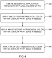
- FIG. 4 is a flowchart depicting a method in accordance with one embodiment.
- the flowchart of FIG. 4 depicts particular method aspects and order of execution. However, it is to be understood that other methods including and/or omitting certain details, and/or proceeding in other orders of execution, can also be used without departing from the scope of the present teachings. Therefore, the method of FIG. 4 is illustrative and non-limiting in nature. For purposes of illustration, it is assumed that two dies defining an overlap print zone within a larger, overall page-wide print array are used in performing the method of FIG. 4 .
- a sequential application hierarchy of plural colors is defined.
- a hierarchy of fours colors is defined as follows: Black ink, then cyan ink, then magenta ink, and then yellow ink.
- Other hierarchies of different colors and/or different numbers of colors, and/or different orders of application, can be defined and used according to the present teachings.
- ink of the first hierarchical color is applied directly to at least a portion of media within the overlap print zone.
- the first ink can be applied at less than full intensity, if so desired. In another instance, the ink of the first hierarchical color is not applied at all.
- One or more width-wise shingles, elongated along a direction of travel of the media, may be defined within the overlap print zone as a result of 402.
- ink of the second hierarchical color is applied within the overlap print zone.
- the second ink can be applied at less than full intensity, if so desired.
- the second ink can, but does not necessarily, overlap at least some of the first ink in the overlap print zone. In another instance, the ink of the second hierarchical color is not applied at all.
- One or more adjacent, width-wise shingles may be defined and/or modified within the overlap print zone as a result of 404.
- the illustrative method according to the present invention continues with the other colors of ink in the predefined hierarchical sequence.
- the ink of the last hierarchical color is applied directly within the overlap print zone.
- the last ink can be applied at less than full intensity, if so desired.
- the last ink can, but does not necessarily, overlap at least some of the other ink(s) within the overlap print zone. In another instance, the ink of the last hierarchical color is not applied at all. At this point, the overall imaging to be formed within the overlap print zone is completed.
Landscapes
- Engineering & Computer Science (AREA)
- Quality & Reliability (AREA)
- Ink Jet (AREA)
Claims (7)
- Procédé exécuté à l'aide d'un dispositif ayant une première matrice (112, 202, 302) et une seconde matrice (114, 204, 304) définissant une zone d'impression de chevauchement (210, 306) par l'application d'une encre d'une première couleur et d'une encre d'une deuxième couleur selon une hiérarchie d'application séquentielle de couleurs définissant un ordre de placement de chevauchement de sorte que l'encre de la première couleur n'est pas appliquée sur l'encre de la deuxième couleur à l'intérieur de la zone d'impression de chevauchement, le procédé comprenant :
avec la première matrice (112, 202, 302) :l'application de l'encre de la première couleur à pleine intensité sur un support (308) à l'intérieur d'une première région (312) de la zone d'impression de chevauchement (210, 306) et l'application de l'encre de la première couleur à intensité partielle sur le support (308) à l'intérieur d'une deuxième région (314) de la zone d'impression de chevauchement (210, 306), la première région (312) et la deuxième région (314) étant des bandes côte à côte ; etl'application de l'encre de la deuxième couleur à intensité partielle sur une partie de la première région (312) de manière à définir une troisième région (320) de la zone d'impression de chevauchement (210, 306) de sorte qu'une bande de la première couleur à pleine intensité est agencée entre la deuxième région (314) et la troisième région (320) ; etavec la seconde matrice (114, 204, 304) :l'application de l'encre de la première couleur à intensité partielle sur la deuxième région (314) pour terminer l'application de l'encre de la première couleur à l'intérieur de la zone d'impression de chevauchement ;l'application de l'encre de la deuxième couleur à intensité partielle sur la troisième région (320), et l'application de l'encre de la deuxième couleur à pleine intensité sur la bande située entre la deuxième région (314) et la troisième région (320) et sur la deuxième région (314), pour terminer l'application de l'encre de la deuxième couleur sur le support, la deuxième région (314), la troisième région (320) et la bande située entre la deuxième région (314) et la troisième région (320) définissant en parallèle des bandes adjacentes sans chevauchement sur le support (308) à l'intérieur de la zone d'impression de chevauchement (210, 306), et la première couleur étant le cyan et la deuxième couleur étant le magenta. - Procédé selon la revendication 1, comprenant en outre l'application d'une encre d'une troisième couleur sur le support (308) à l'intérieur de la zone d'impression de chevauchement (210, 306), l'encre de la première couleur et l'encre de la deuxième couleur n'étant pas appliquées sur l'encre de la troisième couleur à l'intérieur de la zone d'impression de chevauchement (210, 306).
- Procédé selon la revendication 1, comprenant en outre le transport du support (308) dans la proximité imprimable de la zone d'impression de chevauchement (210, 306), les bandes étant allongées le long d'une direction de transport du support (308).
- Procédé selon la revendication 1, la première matrice (112, 202, 302) et la seconde matrice (114, 204, 304) comprenant au moins deux rangées parallèles de buses de décharge d'encre (220), la première matrice (112, 202, 302) et la seconde matrice (114, 204, 304) étant configurées pour appliquer les mêmes couleurs d'encre.
- Procédé selon la revendication 1, la hiérarchie d'application séquentielle de couleurs étant définie par le noir puis le cyan puis le magenta et ensuite le jaune.
- Un ou plusieurs supports de stockage lisibles par ordinateur comportant un code de programme, le code de programme étant configuré pour amener un ou plusieurs processeurs à commander un procédé selon l'une des revendications 1 à 5.
- Dispositif comprenant :une première matrice (112, 202, 302) et une seconde matrice (114, 204, 304) configurées pour décharger de l'encre, la première matrice (112, 202, 302) et la seconde matrice (112, 204, 304) étant positionnées de façon fixe l'une par rapport à l'autre de manière à définir une zone d'impression de chevauchement (210, 306) ; etun dispositif de commande (102) comportant des circuits électroniques, le dispositif de commande (102) étant configuré pour commander un procédé selon l'une des revendications 1 et 2.
Applications Claiming Priority (1)
| Application Number | Priority Date | Filing Date | Title |
|---|---|---|---|
| PCT/US2009/032227 WO2010087819A1 (fr) | 2009-01-28 | 2009-01-28 | Impression avec recouvrement |
Publications (3)
| Publication Number | Publication Date |
|---|---|
| EP2382096A1 EP2382096A1 (fr) | 2011-11-02 |
| EP2382096A4 EP2382096A4 (fr) | 2015-09-09 |
| EP2382096B1 true EP2382096B1 (fr) | 2019-12-18 |
Family
ID=42395869
Family Applications (1)
| Application Number | Title | Priority Date | Filing Date |
|---|---|---|---|
| EP09839394.5A Active EP2382096B1 (fr) | 2009-01-28 | 2009-01-28 | Impression avec recouvrement |
Country Status (4)
| Country | Link |
|---|---|
| US (1) | US8480207B2 (fr) |
| EP (1) | EP2382096B1 (fr) |
| CN (1) | CN102300714B (fr) |
| WO (1) | WO2010087819A1 (fr) |
Families Citing this family (5)
| Publication number | Priority date | Publication date | Assignee | Title |
|---|---|---|---|---|
| JP6432247B2 (ja) | 2014-09-26 | 2018-12-05 | ブラザー工業株式会社 | インクジェットプリンタ |
| WO2016057015A1 (fr) * | 2014-10-06 | 2016-04-14 | Hewlett-Packard Industrial Printing Ltd. | Ensemble matrice de tête d'impression |
| WO2016165777A1 (fr) * | 2015-04-17 | 2016-10-20 | Hewlett-Packard Development Company, L.P. | Imprimantes et procédés pour les commander |
| JP6610132B2 (ja) * | 2015-09-30 | 2019-11-27 | ブラザー工業株式会社 | プリンタ |
| JP7338241B2 (ja) * | 2019-05-28 | 2023-09-05 | コニカミノルタ株式会社 | インクジェット記録装置、インクジェット記録方法及びインクジェット記録プログラム |
Family Cites Families (11)
| Publication number | Priority date | Publication date | Assignee | Title |
|---|---|---|---|---|
| US6578950B2 (en) | 2000-08-28 | 2003-06-17 | Fuji Photo Film Co., Ltd. | Line head and image recording method |
| JP4629956B2 (ja) * | 2002-11-28 | 2011-02-09 | コニカミノルタホールディングス株式会社 | インクジェットプリンタ |
| JP4298486B2 (ja) * | 2003-12-03 | 2009-07-22 | キヤノン株式会社 | 記録装置及びその記録方法並びにプログラム |
| JP4027358B2 (ja) * | 2003-12-15 | 2007-12-26 | キヤノン株式会社 | インクジェットヘッドおよび該ヘッドを用いるインクジェット記録装置 |
| US7517052B2 (en) * | 2003-12-15 | 2009-04-14 | Canon Kabushiki Kaisha | Ink-jet head and ink-jet recording apparatus using the head |
| US7311383B2 (en) * | 2004-03-26 | 2007-12-25 | Canon Kabushiki Kaisha | Liquid discharge recording apparatus and liquid discharge recording method |
| US7264324B2 (en) * | 2004-12-17 | 2007-09-04 | Xerox Corporation | Method and apparatus with vernier technique for registration of ejector module |
| JP4689353B2 (ja) * | 2005-06-01 | 2011-05-25 | キヤノン株式会社 | インクジェット記録装置、及び記録方法 |
| JP4804043B2 (ja) * | 2005-06-03 | 2011-10-26 | キヤノン株式会社 | インクジェット記録装置、インクジェット記録方法、および記録制御形態の設定方法 |
| JP5213317B2 (ja) * | 2006-08-22 | 2013-06-19 | キヤノン株式会社 | インクジェット記録装置およびインクジェット記録方法 |
| JP4994819B2 (ja) | 2006-12-11 | 2012-08-08 | キヤノン株式会社 | 記録装置及びデータ生成方法 |
-
2009
- 2009-01-28 EP EP09839394.5A patent/EP2382096B1/fr active Active
- 2009-01-28 WO PCT/US2009/032227 patent/WO2010087819A1/fr not_active Ceased
- 2009-01-28 CN CN200980155562.0A patent/CN102300714B/zh not_active Expired - Fee Related
- 2009-01-28 US US13/130,281 patent/US8480207B2/en not_active Expired - Fee Related
Non-Patent Citations (1)
| Title |
|---|
| None * |
Also Published As
| Publication number | Publication date |
|---|---|
| WO2010087819A1 (fr) | 2010-08-05 |
| US8480207B2 (en) | 2013-07-09 |
| EP2382096A4 (fr) | 2015-09-09 |
| CN102300714B (zh) | 2016-03-16 |
| CN102300714A (zh) | 2011-12-28 |
| EP2382096A1 (fr) | 2011-11-02 |
| US20110228002A1 (en) | 2011-09-22 |
Similar Documents
| Publication | Publication Date | Title |
|---|---|---|
| JP5326924B2 (ja) | 流体噴射装置、及び、流体噴射方法 | |
| US20070242098A1 (en) | Method of determining ink ejection method, printing apparatus, and method of manufacturing printing apparatus | |
| EP2382096B1 (fr) | Impression avec recouvrement | |
| JP2009234116A (ja) | 補正値算出方法、及び、液体吐出方法 | |
| JP5668462B2 (ja) | 印刷装置及び印刷方法 | |
| JP4508247B2 (ja) | 記録制御装置、記録制御方法、及び記録制御プログラム | |
| US6938970B2 (en) | Printing methods and apparatus for multi-pass printing | |
| JP2013184458A (ja) | 画像記録装置及び方法 | |
| US7971951B2 (en) | Inkjet printing apparatus and printing method therefor | |
| US20190134990A1 (en) | Method and system for compensating for a malfunctioning nozzle | |
| US20180297358A1 (en) | Inkjet printer and printing method | |
| US9218549B2 (en) | Printing apparatus and print control method | |
| JP5471112B2 (ja) | 印刷装置、印刷方法およびプログラム | |
| JP2011189592A (ja) | 液体吐出装置及び液体吐出方法 | |
| US10654276B2 (en) | Ink-jet printing device and ink-jet printing method | |
| JP2008238811A (ja) | インクジェット記録装置及びその記録方法 | |
| JP5679011B2 (ja) | 流体噴射装置、及び、流体噴射方法 | |
| JP2013215979A (ja) | 印刷装置、印刷方法、及び、印刷物 | |
| US10675896B2 (en) | Image recording apparatus | |
| US7036900B2 (en) | Printing method and apparatus for back-up of defective marking elements | |
| JP6870646B2 (ja) | 液体吐出装置 | |
| US7559624B2 (en) | Printer device and control method thereof | |
| EP1676710B1 (fr) | Dispositif d'impression et sa méthode de commande | |
| EP1344651B1 (fr) | Méthode d'impression et appareil pour remplacer les éléments d'impression défectueux | |
| JP5460048B2 (ja) | インクジェット記録装置、及びインクジェット記録方法 |
Legal Events
| Date | Code | Title | Description |
|---|---|---|---|
| PUAI | Public reference made under article 153(3) epc to a published international application that has entered the european phase |
Free format text: ORIGINAL CODE: 0009012 |
|
| 17P | Request for examination filed |
Effective date: 20110406 |
|
| AK | Designated contracting states |
Kind code of ref document: A1 Designated state(s): AT BE BG CH CY CZ DE DK EE ES FI FR GB GR HR HU IE IS IT LI LT LU LV MC MK MT NL NO PL PT RO SE SI SK TR |
|
| RIN1 | Information on inventor provided before grant (corrected) |
Inventor name: MACKENZIE, MARK H. Inventor name: KINAS, ERICK B. Inventor name: SHEPHERD, MATTHEW A. |
|
| RIN1 | Information on inventor provided before grant (corrected) |
Inventor name: MACKENZIE, MARK H. Inventor name: KINAS, ERICK B. Inventor name: SHEPHERD, MATTHEW A. |
|
| DAX | Request for extension of the european patent (deleted) | ||
| RA4 | Supplementary search report drawn up and despatched (corrected) |
Effective date: 20150807 |
|
| RIC1 | Information provided on ipc code assigned before grant |
Ipc: B41J 2/04 20060101AFI20150803BHEP Ipc: B41J 2/21 20060101ALI20150803BHEP Ipc: B41J 2/15 20060101ALI20150803BHEP |
|
| STAA | Information on the status of an ep patent application or granted ep patent |
Free format text: STATUS: EXAMINATION IS IN PROGRESS |
|
| 17Q | First examination report despatched |
Effective date: 20180219 |
|
| RAP1 | Party data changed (applicant data changed or rights of an application transferred) |
Owner name: HEWLETT-PACKARD DEVELOPMENT COMPANY, L.P. |
|
| REG | Reference to a national code |
Ref country code: DE Ref legal event code: R079 Ref document number: 602009060773 Country of ref document: DE Free format text: PREVIOUS MAIN CLASS: B41J0002040000 Ipc: B41J0002155000 |
|
| RIC1 | Information provided on ipc code assigned before grant |
Ipc: B41J 2/155 20060101AFI20190611BHEP Ipc: B41J 2/21 20060101ALI20190611BHEP |
|
| GRAP | Despatch of communication of intention to grant a patent |
Free format text: ORIGINAL CODE: EPIDOSNIGR1 |
|
| STAA | Information on the status of an ep patent application or granted ep patent |
Free format text: STATUS: GRANT OF PATENT IS INTENDED |
|
| INTG | Intention to grant announced |
Effective date: 20190730 |
|
| GRAS | Grant fee paid |
Free format text: ORIGINAL CODE: EPIDOSNIGR3 |
|
| GRAA | (expected) grant |
Free format text: ORIGINAL CODE: 0009210 |
|
| STAA | Information on the status of an ep patent application or granted ep patent |
Free format text: STATUS: THE PATENT HAS BEEN GRANTED |
|
| AK | Designated contracting states |
Kind code of ref document: B1 Designated state(s): AT BE BG CH CY CZ DE DK EE ES FI FR GB GR HR HU IE IS IT LI LT LU LV MC MK MT NL NO PL PT RO SE SI SK TR |
|
| REG | Reference to a national code |
Ref country code: GB Ref legal event code: FG4D |
|
| REG | Reference to a national code |
Ref country code: CH Ref legal event code: EP |
|
| REG | Reference to a national code |
Ref country code: DE Ref legal event code: R096 Ref document number: 602009060773 Country of ref document: DE |
|
| REG | Reference to a national code |
Ref country code: IE Ref legal event code: FG4D |
|
| REG | Reference to a national code |
Ref country code: AT Ref legal event code: REF Ref document number: 1214144 Country of ref document: AT Kind code of ref document: T Effective date: 20200115 |
|
| REG | Reference to a national code |
Ref country code: NL Ref legal event code: MP Effective date: 20191218 |
|
| PG25 | Lapsed in a contracting state [announced via postgrant information from national office to epo] |
Ref country code: FI Free format text: LAPSE BECAUSE OF FAILURE TO SUBMIT A TRANSLATION OF THE DESCRIPTION OR TO PAY THE FEE WITHIN THE PRESCRIBED TIME-LIMIT Effective date: 20191218 Ref country code: BG Free format text: LAPSE BECAUSE OF FAILURE TO SUBMIT A TRANSLATION OF THE DESCRIPTION OR TO PAY THE FEE WITHIN THE PRESCRIBED TIME-LIMIT Effective date: 20200318 Ref country code: LT Free format text: LAPSE BECAUSE OF FAILURE TO SUBMIT A TRANSLATION OF THE DESCRIPTION OR TO PAY THE FEE WITHIN THE PRESCRIBED TIME-LIMIT Effective date: 20191218 Ref country code: NO Free format text: LAPSE BECAUSE OF FAILURE TO SUBMIT A TRANSLATION OF THE DESCRIPTION OR TO PAY THE FEE WITHIN THE PRESCRIBED TIME-LIMIT Effective date: 20200318 Ref country code: GR Free format text: LAPSE BECAUSE OF FAILURE TO SUBMIT A TRANSLATION OF THE DESCRIPTION OR TO PAY THE FEE WITHIN THE PRESCRIBED TIME-LIMIT Effective date: 20200319 Ref country code: LV Free format text: LAPSE BECAUSE OF FAILURE TO SUBMIT A TRANSLATION OF THE DESCRIPTION OR TO PAY THE FEE WITHIN THE PRESCRIBED TIME-LIMIT Effective date: 20191218 Ref country code: SE Free format text: LAPSE BECAUSE OF FAILURE TO SUBMIT A TRANSLATION OF THE DESCRIPTION OR TO PAY THE FEE WITHIN THE PRESCRIBED TIME-LIMIT Effective date: 20191218 |
|
| PGFP | Annual fee paid to national office [announced via postgrant information from national office to epo] |
Ref country code: GB Payment date: 20200221 Year of fee payment: 12 Ref country code: DE Payment date: 20200218 Year of fee payment: 12 |
|
| REG | Reference to a national code |
Ref country code: LT Ref legal event code: MG4D |
|
| PG25 | Lapsed in a contracting state [announced via postgrant information from national office to epo] |
Ref country code: HR Free format text: LAPSE BECAUSE OF FAILURE TO SUBMIT A TRANSLATION OF THE DESCRIPTION OR TO PAY THE FEE WITHIN THE PRESCRIBED TIME-LIMIT Effective date: 20191218 |
|
| PGFP | Annual fee paid to national office [announced via postgrant information from national office to epo] |
Ref country code: FR Payment date: 20200131 Year of fee payment: 12 |
|
| PG25 | Lapsed in a contracting state [announced via postgrant information from national office to epo] |
Ref country code: RO Free format text: LAPSE BECAUSE OF FAILURE TO SUBMIT A TRANSLATION OF THE DESCRIPTION OR TO PAY THE FEE WITHIN THE PRESCRIBED TIME-LIMIT Effective date: 20191218 Ref country code: NL Free format text: LAPSE BECAUSE OF FAILURE TO SUBMIT A TRANSLATION OF THE DESCRIPTION OR TO PAY THE FEE WITHIN THE PRESCRIBED TIME-LIMIT Effective date: 20191218 Ref country code: EE Free format text: LAPSE BECAUSE OF FAILURE TO SUBMIT A TRANSLATION OF THE DESCRIPTION OR TO PAY THE FEE WITHIN THE PRESCRIBED TIME-LIMIT Effective date: 20191218 Ref country code: CZ Free format text: LAPSE BECAUSE OF FAILURE TO SUBMIT A TRANSLATION OF THE DESCRIPTION OR TO PAY THE FEE WITHIN THE PRESCRIBED TIME-LIMIT Effective date: 20191218 Ref country code: PT Free format text: LAPSE BECAUSE OF FAILURE TO SUBMIT A TRANSLATION OF THE DESCRIPTION OR TO PAY THE FEE WITHIN THE PRESCRIBED TIME-LIMIT Effective date: 20200513 |
|
| PG25 | Lapsed in a contracting state [announced via postgrant information from national office to epo] |
Ref country code: SK Free format text: LAPSE BECAUSE OF FAILURE TO SUBMIT A TRANSLATION OF THE DESCRIPTION OR TO PAY THE FEE WITHIN THE PRESCRIBED TIME-LIMIT Effective date: 20191218 Ref country code: IS Free format text: LAPSE BECAUSE OF FAILURE TO SUBMIT A TRANSLATION OF THE DESCRIPTION OR TO PAY THE FEE WITHIN THE PRESCRIBED TIME-LIMIT Effective date: 20200418 |
|
| REG | Reference to a national code |
Ref country code: CH Ref legal event code: PL |
|
| REG | Reference to a national code |
Ref country code: DE Ref legal event code: R097 Ref document number: 602009060773 Country of ref document: DE |
|
| PG25 | Lapsed in a contracting state [announced via postgrant information from national office to epo] |
Ref country code: MC Free format text: LAPSE BECAUSE OF FAILURE TO SUBMIT A TRANSLATION OF THE DESCRIPTION OR TO PAY THE FEE WITHIN THE PRESCRIBED TIME-LIMIT Effective date: 20191218 |
|
| REG | Reference to a national code |
Ref country code: BE Ref legal event code: MM Effective date: 20200131 Ref country code: AT Ref legal event code: MK05 Ref document number: 1214144 Country of ref document: AT Kind code of ref document: T Effective date: 20191218 |
|
| PLBE | No opposition filed within time limit |
Free format text: ORIGINAL CODE: 0009261 |
|
| STAA | Information on the status of an ep patent application or granted ep patent |
Free format text: STATUS: NO OPPOSITION FILED WITHIN TIME LIMIT |
|
| PG25 | Lapsed in a contracting state [announced via postgrant information from national office to epo] |
Ref country code: DK Free format text: LAPSE BECAUSE OF FAILURE TO SUBMIT A TRANSLATION OF THE DESCRIPTION OR TO PAY THE FEE WITHIN THE PRESCRIBED TIME-LIMIT Effective date: 20191218 Ref country code: ES Free format text: LAPSE BECAUSE OF FAILURE TO SUBMIT A TRANSLATION OF THE DESCRIPTION OR TO PAY THE FEE WITHIN THE PRESCRIBED TIME-LIMIT Effective date: 20191218 Ref country code: LU Free format text: LAPSE BECAUSE OF NON-PAYMENT OF DUE FEES Effective date: 20200128 |
|
| 26N | No opposition filed |
Effective date: 20200921 |
|
| PG25 | Lapsed in a contracting state [announced via postgrant information from national office to epo] |
Ref country code: AT Free format text: LAPSE BECAUSE OF FAILURE TO SUBMIT A TRANSLATION OF THE DESCRIPTION OR TO PAY THE FEE WITHIN THE PRESCRIBED TIME-LIMIT Effective date: 20191218 Ref country code: LI Free format text: LAPSE BECAUSE OF NON-PAYMENT OF DUE FEES Effective date: 20200131 Ref country code: SI Free format text: LAPSE BECAUSE OF FAILURE TO SUBMIT A TRANSLATION OF THE DESCRIPTION OR TO PAY THE FEE WITHIN THE PRESCRIBED TIME-LIMIT Effective date: 20191218 Ref country code: CH Free format text: LAPSE BECAUSE OF NON-PAYMENT OF DUE FEES Effective date: 20200131 Ref country code: BE Free format text: LAPSE BECAUSE OF NON-PAYMENT OF DUE FEES Effective date: 20200131 |
|
| PG25 | Lapsed in a contracting state [announced via postgrant information from national office to epo] |
Ref country code: IE Free format text: LAPSE BECAUSE OF NON-PAYMENT OF DUE FEES Effective date: 20200128 Ref country code: IT Free format text: LAPSE BECAUSE OF FAILURE TO SUBMIT A TRANSLATION OF THE DESCRIPTION OR TO PAY THE FEE WITHIN THE PRESCRIBED TIME-LIMIT Effective date: 20191218 |
|
| PG25 | Lapsed in a contracting state [announced via postgrant information from national office to epo] |
Ref country code: PL Free format text: LAPSE BECAUSE OF FAILURE TO SUBMIT A TRANSLATION OF THE DESCRIPTION OR TO PAY THE FEE WITHIN THE PRESCRIBED TIME-LIMIT Effective date: 20191218 |
|
| REG | Reference to a national code |
Ref country code: DE Ref legal event code: R119 Ref document number: 602009060773 Country of ref document: DE |
|
| GBPC | Gb: european patent ceased through non-payment of renewal fee |
Effective date: 20210128 |
|
| PG25 | Lapsed in a contracting state [announced via postgrant information from national office to epo] |
Ref country code: FR Free format text: LAPSE BECAUSE OF NON-PAYMENT OF DUE FEES Effective date: 20210131 |
|
| PG25 | Lapsed in a contracting state [announced via postgrant information from national office to epo] |
Ref country code: DE Free format text: LAPSE BECAUSE OF NON-PAYMENT OF DUE FEES Effective date: 20210803 Ref country code: GB Free format text: LAPSE BECAUSE OF NON-PAYMENT OF DUE FEES Effective date: 20210128 |
|
| PG25 | Lapsed in a contracting state [announced via postgrant information from national office to epo] |
Ref country code: TR Free format text: LAPSE BECAUSE OF FAILURE TO SUBMIT A TRANSLATION OF THE DESCRIPTION OR TO PAY THE FEE WITHIN THE PRESCRIBED TIME-LIMIT Effective date: 20191218 Ref country code: MT Free format text: LAPSE BECAUSE OF FAILURE TO SUBMIT A TRANSLATION OF THE DESCRIPTION OR TO PAY THE FEE WITHIN THE PRESCRIBED TIME-LIMIT Effective date: 20191218 Ref country code: CY Free format text: LAPSE BECAUSE OF FAILURE TO SUBMIT A TRANSLATION OF THE DESCRIPTION OR TO PAY THE FEE WITHIN THE PRESCRIBED TIME-LIMIT Effective date: 20191218 |
|
| PG25 | Lapsed in a contracting state [announced via postgrant information from national office to epo] |
Ref country code: MK Free format text: LAPSE BECAUSE OF FAILURE TO SUBMIT A TRANSLATION OF THE DESCRIPTION OR TO PAY THE FEE WITHIN THE PRESCRIBED TIME-LIMIT Effective date: 20191218 |