EP2382933A1 - Système cathéter à ballon - Google Patents
Système cathéter à ballon Download PDFInfo
- Publication number
- EP2382933A1 EP2382933A1 EP08878934A EP08878934A EP2382933A1 EP 2382933 A1 EP2382933 A1 EP 2382933A1 EP 08878934 A EP08878934 A EP 08878934A EP 08878934 A EP08878934 A EP 08878934A EP 2382933 A1 EP2382933 A1 EP 2382933A1
- Authority
- EP
- European Patent Office
- Prior art keywords
- balloon
- temperature
- electrode
- temperature sensor
- inner tube
- Prior art date
- Legal status (The legal status is an assumption and is not a legal conclusion. Google has not performed a legal analysis and makes no representation as to the accuracy of the status listed.)
- Granted
Links
Images


Classifications
-
- A—HUMAN NECESSITIES
- A61—MEDICAL OR VETERINARY SCIENCE; HYGIENE
- A61B—DIAGNOSIS; SURGERY; IDENTIFICATION
- A61B18/00—Surgical instruments, devices or methods for transferring non-mechanical forms of energy to or from the body
- A61B18/04—Surgical instruments, devices or methods for transferring non-mechanical forms of energy to or from the body by heating
- A61B18/12—Surgical instruments, devices or methods for transferring non-mechanical forms of energy to or from the body by heating by passing a current through the tissue to be heated, e.g. high-frequency current
- A61B18/14—Probes or electrodes therefor
- A61B18/1492—Probes or electrodes therefor having a flexible, catheter-like structure, e.g. for heart ablation
-
- A—HUMAN NECESSITIES
- A61—MEDICAL OR VETERINARY SCIENCE; HYGIENE
- A61B—DIAGNOSIS; SURGERY; IDENTIFICATION
- A61B18/00—Surgical instruments, devices or methods for transferring non-mechanical forms of energy to or from the body
- A61B18/04—Surgical instruments, devices or methods for transferring non-mechanical forms of energy to or from the body by heating
- A61B18/08—Surgical instruments, devices or methods for transferring non-mechanical forms of energy to or from the body by heating by means of electrically-heated probes
-
- A—HUMAN NECESSITIES
- A61—MEDICAL OR VETERINARY SCIENCE; HYGIENE
- A61B—DIAGNOSIS; SURGERY; IDENTIFICATION
- A61B17/00—Surgical instruments, devices or methods
- A61B2017/00017—Electrical control of surgical instruments
- A61B2017/00022—Sensing or detecting at the treatment site
- A61B2017/00084—Temperature
-
- A—HUMAN NECESSITIES
- A61—MEDICAL OR VETERINARY SCIENCE; HYGIENE
- A61B—DIAGNOSIS; SURGERY; IDENTIFICATION
- A61B18/00—Surgical instruments, devices or methods for transferring non-mechanical forms of energy to or from the body
- A61B2018/00053—Mechanical features of the instrument of device
- A61B2018/00214—Expandable means emitting energy, e.g. by elements carried thereon
- A61B2018/0022—Balloons
-
- A—HUMAN NECESSITIES
- A61—MEDICAL OR VETERINARY SCIENCE; HYGIENE
- A61B—DIAGNOSIS; SURGERY; IDENTIFICATION
- A61B18/00—Surgical instruments, devices or methods for transferring non-mechanical forms of energy to or from the body
- A61B18/04—Surgical instruments, devices or methods for transferring non-mechanical forms of energy to or from the body by heating
- A61B18/12—Surgical instruments, devices or methods for transferring non-mechanical forms of energy to or from the body by heating by passing a current through the tissue to be heated, e.g. high-frequency current
- A61B18/14—Probes or electrodes therefor
- A61B2018/1405—Electrodes having a specific shape
- A61B2018/1435—Spiral
- A61B2018/1437—Spiral whereby the windings of the spiral touch each other such as to create a continuous surface
Definitions
- the present invention relates to a balloon catheter system, particularly to a balloon catheter system employed for a thermal therapy used for ablating, at appropriate temperatures, a source origin of arrhythmia, an unstable atherosclerotic lesion, proliferated smooth muscles which cause bronchial asthma, cancer tissues or the like.
- a balloon catheter system e.g., refer to patent documents 1, 2
- This balloon catheter system is equipped with a balloon provided with an electrode for delivery of radiofrequency current therein.
- a radiofrequency current is applied to the electrode for delivery of radiofrequency current and thereby an inside of the balloon is heated to raise a surface temperature of the balloon and then the tissue in contact with the balloon is directly ablated.
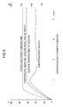
- a tissue depth ablated by the balloon (when the tissue temperature is at 45 degrees or more) is proportional to the surface temperature of the balloon and the delivery time of radiofrequency current and therefore it is of extreme importance to predict the surface temperature of the balloon ( FIG. 6 ).
- the temperature sensor of the traditional balloon catheter system was arranged in the vicinity of the electrode for delivery of radiofrequency current.
- a temperature senor there was a significant difference between a measured temperature indicated by a temperature senor and a surface temperature of the balloon in contact with tissue.
- the larger the size of a balloon the larger the difference between the temperatures.
- the temperature rise at the surface of the balloon lagged behind that at the electrode for delivery of radiofrequency current, thus making it difficult to predict the surface temperature of the balloon ( FIG.5 ).
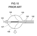
- a temperature sensor 108 is set in contact with an inner surface of a balloon 106.
- numeral 107 denotes an electrode for delivery of radiofrequency current and lead wires 135 of the temperature sensor 108 are allowed to pass through a portion between an outer tube 102 and an inner tube 103 to be connected to a thermometer, not shown, externally arranged.
- the temperature sensor 108 was allowed to contact with the balloon 106 and therefore the balloon 106 became voluminous, leading to difficulty in manipulation. Further problem was presented that a pinhole was prone to be produced in a position where the balloon 106 contacted with the temperature sensor 108.
- an object of the present invention to provide a balloon catheter system capable of precisely detecting a surface temperature of a balloon without allowing the balloon to contact with the temperature sensor.
- a first aspect of the present invention is a balloon catheter system comprising: a catheter shaft comprising an outer tube and an inner tube which are slidable to each other, a balloon provided between a distal end of said outer tube and a vicinity of a distal end of said inner tube, an electrode for delivery of radiofrequency current provided in a central portion of said balloon, an external radiofrequency generator which supplies radiofrequency energy to said electrode for delivery of radiofrequency current through a lead wire to heat said balloon; an external thermometer which detects a temperature through a lead wire of a temperature sensor via said temperature sensor provided inside said balloon and its lead wires; a solution transport path formed between said outer tube and said inner tube, in communication with an inside of said balloon; an external vibration generator which applies vibrational waves to said balloon through said solution transport path to generate swirls inside said balloon and thereby makes the temperature inside said balloon uniform; and a guide wire which guides said balloon to a target site, wherein said temperature sensor is separated from said electrode for delivery of radiofrequency current and is fixed to the distal
- a second aspect of the present invention is a balloon catheter system, wherein a heat insulating material is interposed between said temperature sensor and said electrode for delivery of radiofrequency current.
- a third aspect of the present invention is a balloon catheter system, wherein a heat insulating material is interposed between said temperature sensor and said inner tube.
- a fourth aspect of the present invention is a balloon catheter system, wherein a heat insulating space is provided between said temperature sensor and said inner tube.
- a fifth aspect of the present invention is a balloon catheter system, wherein said temperature sensor is formed into a tubular shape encircling an entire circumference of said inner tube or is equipped with a tubular good thermal conductor encircling the entire circumference of said inner tube and besides is connected with said tubular good thermal conductor.
- a sixth aspect of the present invention is a balloon catheter system, wherein said electrode for delivery of radiofrequency current is monopolar or a bipolar, and when monopolar, a radiofrequency current is applied across said electrode and a counter electrode externally provided, while when bipolar, a radiofrequency current is applied across both electrodes.
- a seventh aspect of the present invention is a balloon catheter system, wherein an electrode temperature sensor which detects the temperature of said electrode for delivery of radiofrequency current is provided and said sensor is covered with an insulation material.
- An eighth aspect of the present invention is a balloon catheter system, wherein a balloon external heat shield knob is arranged in the vicinity of the distal end of said tube, in contact with an outer surface of said balloon.
- a ninth aspect of the present invention is a balloon catheter system, wherein as substitute for said electrode for delivery of radiofrequency current and said external radiofrequency generator, said balloon catheter system is equipped with any one of couples of an ultrasonic heating element and an ultrasonic generator, a laser heating element and a laser generator, a diode heating element and a diode power supply, and a nichrome wire heating element and a nichrome wire power supply unit.
- the balloon catheter system of the present invention when a vibrational wave with a suitable frequency (e.g., 25Hz) and a suitable waveform (e.g., an asymmetric pulse wave) is applied to an inside of the balloon by means of the external vibration generator, large swirls running vertically in relation to gravity are generated inside the balloon under the influence of gravity to cancel a temperature gradient due to convective heat.
- the temperature sensor is fixed to the distal end of the inner tube inside the balloon so as to make it possible to detect the temperature of the swirls flowing along the inner surface of the balloon.
- the temperature of the swirls flowing along the inner surface of the balloon is approximate to the surface temperature of the balloon.
- the heat insulating material is interposed between the temperature sensor and the electrode for delivery of radiofrequency current.
- the temperature sensor can be prevented from being directly heated by the electrode for delivery of radiofrequency current, permitting the temperature of the swirls approximate to the surface temperature of the balloon to be precisely detected.
- the heat insulating material is interposed between the temperature sensor and the inner tube. Hence, even if the guide wire passing through the inside of the inner tube is heated by radiofrequency electromagnetic coupling, the surface temperature of the balloon can be precisely detected by preventing the influence of the heat resulting from the radiofrequency electromagnetic coupling.
- a heat insulating space is provided between the temperature sensor and the inner tube.
- the temperature sensor is formed into a tubular shape encircling the entire circumference of the inner tube or is equipped with the tubular good thermal conductor encircling the entire circumference of the inner tube and besides is connected with the tubular good thermal conductor.
- the electrode for delivery of radiofrequency current is monopolar or bipolar. Hence, when monopolar, a radiofrequency current is applied across said electrode and the counter electrode externally provided and when bipolar, a radiofrequency current is applied across both electrodes. Hence, the electrode for delivery of radiofrequency current can be heated.
- the electrode temperature sensor is provided which detects the temperature of the electrode for delivery of radiofrequency current and further is covered with the heat insulating material. Hence, the temperature of the electrode for delivery of radiofrequency current can be precisely detected without being affected by the swirls.
- the balloon external heat shield knob is provided in contact with the outer surface of the balloon.
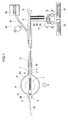
- FIGs. 1 to 3 show one embodiment of a balloon catheter system according to the present invention.
- Numeral 1 denotes a catheter shaft, which comprises an outer tube 2 and an inner tube 3 which are slidable to each other.
- a balloon 6 is provided between a distal end 4 of the outer tube 2 and a vicinity of a distal end 5 of the inner tube 3.
- the balloon 6 is formed from synthetic resin such as polyurethane or the like. The balloon 6 dilates into an approximately spherical form by filling an inside of the balloon 6 with a solution.
- the electrode 7 for delivery of radiofrequency current for heating the inside of the balloon 6 is wound around the inner tube 3 in a coiled fashion to be provided in a central part of the balloon 6. Then, the electrode 7 for delivery of radiofrequency current is monopolar and is able to conduct a radiofrequency current between itself and a counter electrode, not shown, provided outside the catheter shaft 1. Then, the electrode 7 for delivery of radiofrequency current generates heat by applying a radiofrequency current thereto. Alternatively, the electrode 7 for delivery of radiofrequency current may be bipolar to apply a radiofrequency current across both electrodes.
- a temperature sensor 8 for detecting the temperature inside the balloon 6 is fixed in the vicinity of the distal end 5 of the inner tube 3.
- an electrode temperature sensor 10 for detecting the temperature of the electrode 7 for delivery of radiofrequency current is arranged in contact with the electrode 7 for delivery of radiofrequency current, and is fixed on a side closer to a proximal end 9 of the inner tube 3.
- a solution transport path 11 is formed which communicates with the inside of the balloon 6.
- a guide wire 12 for guiding the balloon 6 to a target site is provided in such a fashion as to be inserted through the inner tube 3.
- a heat insulating material 21 is interposed between the temperature sensor 8 and the electrode 7 for delivery of radiofrequency current.
- the temperature sensor 8 can be prevented from being directly heated by the electrode 7 for delivery of radiofrequency current and thus the temperature inside the balloon 6 can be precisely detected.
- a heat insulating material 22 is interposed between the temperature sensor 8 and the inner tube 3, as shown in FIG. 2(a) .
- the temperature sensor 8 can be prevented from being affected by the heat of the guide wire 12, thus permitting the temperature inside the balloon 6 to be precisely detected.
- a heat insulating space 23 may be provided between the temperature sensor 8 and the inner tube 3. Even in this way, the temperature sensor 8 can be prevented from being affected by the guide wire 12 heated by radiofrequency electromagnetic coupling.
- a tubular good thermal conductor 24 encircling an entire circumference of the inner tube 3 may be provided and the temperature sensor 8 may be coupled to this tubular good thermal conductor, otherwise the temperature sensor 8 may be formed into a tubular shape encircling the entire circumference of the inner tube 3.
- the temperature inside the balloon 6 can be precisely detected by means of detecting the temperature from the entire circumference of the inner tube 3.
- the electrode temperature sensor 10 is covered with an insulating body 25 and therefore can precisely detect the temperature of the electrode 7 for delivery of radiofrequency current without being affected by the swirl S.
- a balloon external heat shield knob 26 is provided in contact with an outer surface of the balloon 6.
- the temperature sensor 8 provided in the vicinity of the distal end 5 of the inner tube 3 inside the balloon 6 can be prevented from being affected by temperature of blood or the like contacting with the balloon 6, thus permitting the temperature inside the balloon 6 to be precisely detected.
- the inner tube 3 passes through a central portion of the balloon external heat shield knob 26, which is fixed to the inner tube 3.
- an external radiofrequency generator 31 for supplying radiofrequency energy for heating the balloon 6 to the electrode 7 for delivery of radiofrequency current, an thermometer 32 for indicating the temperature detected by the temperature sensor 8, and an electrode thermometer 33 for indicating the temperature detected by the electrode temperature sensor 10.
- the electrode 7 for delivery of radiofrequency current and the external radiofrequency generator 31 are connected electrically to each other through a lead wire 34, while the temperature sensor 8 and the external thermometer 32, the electrode temperature sensor 10 and the electrode thermometer 33 are connected electrically to each other by lead wires 35, 36, respectively. Further, between the distal end 5 of the inner tube 3 and the proximal end 9, the lead wires 34, 35 and 36 are fixed to the inner tube 3.
- a syringe 41 for supplying the solution to the balloon 6 through the solution transport path 11 and a vibration generator 42 for applying asymmetric vibrational waves W the balloon 6 through the solution transport path 11 to steadily generate swirls S inside the balloon 6. Then, a diameter of the balloon 6 is changed by varying pressure of the solution supplied to the balloon 6 by means of the syringe 41. The solution inside the balloon 6 is agitated by the swirls S to keep the temperature inside the balloon 6 uniform.
- the electrode 7 for delivery of radiofrequency current fixed to the vicinity of the distal end of the inner tube 3 is employed in order to heat the inside of the balloon 6. Any one capable of heating the inside of the balloon 6, however, may be applicable without confining to a specific device.
- the electrode 7 for delivery of radiofrequency current and the radiofrequency generator 31 any one of couples of an ultrasonic heating element and ultrasonic generator, a laser heating element and laser generator, a diode heating element and diode power supply, and a nichrome wire heating element and nichrome wire power supply unit may be applicable.
- a liquid containing a physiological saline, a contrast medium or the like are infused from a syringe 41 into a catheter inner cavity, i.e., the solution transport path 11 and the inside of the balloon 6 to thereby perform air bleeding.
- the balloon 6 is allowed to contract with the outer and inner tubes mutually slid so as to maximize a distance between the distal end 4 of the outer tube 3 and that 5 of the inner tube 3.
- a sheath-shaped guiding sheath for guiding the catheter shaft 1 is inserted into a vicinity of a target site A inside a patient body.
- the contracted balloon 6 is inserted into the guiding sheath to make the balloon 6 stay in the vicinity of the target site A.
- the liquid is infused from the syringe 41 into the balloon 6 to dilate the balloon 6.
- the balloon 6 is adjusted in length by adjusting the distance between the distal end 4 of the outer tube 2 and the distal end 5 of the inner tube 3 and then the balloon 6 is adjusted in diameter by adjusting pressure of the liquid supplied to the balloon 6 by the syringe 41. Then, the balloon 6 is pressed against the target site A.
- the lead wires 34, 35 and 36 each connected to the electrode 7 for delivery of radiofrequency current, the temperature sensor 8 and the electrode temperature sensor 10, respectively, are connected, from the proximal portion 9 of the inner tube 3, to the radiofrequency generator 31, the thermometer 32 and the electrode thermometer 33, respectively.
- an output of the radiofrequency generator 31 is built up while observing the thermometer 32 and the electrode thermometer 33.
- the vibration generator 42 is allowed to start to feed a 2.5Hz vibrational wave W into the inside of the balloon 6 through the solution transport path 11.
- the swirl S vertical in relation to the gravity is generated inside the balloon 6 to eliminate a temperature difference resulting from the convection inside the balloon 6.
- the temperature sensor 8 is arranged at a position where the swirl S flows in the vicinity of the distal end 5 of the inner tube 3, i.e., in the vicinity of the balloon 6. Hence, the temperature of the swirl S in the vicinity of the balloon 6 can be precisely detected.
- the temperature of the swirl S in the vicinity of the balloon 6 is substantially constant in a steady state to be approximate to the surface temperature of the balloon 6. Consequently, the surface temperature of the balloon 6 can be almost precisely detected by means of detecting the temperature of the swirl S in the vicinity of the balloon 6.
- a target site A in contact with the balloon 6 is ablated while regulating the surface temperature of the balloon 6 and the delivery time of radiofrequency current.
- an ablating depth of the tissue of the target site A is proportional to the surface temperature of the balloon 6, by regulating the surface temperature of the balloon 6, the ablated depth can be precisely controlled. Accordingly, specifically in the therapy of atrial fibrillation, the atrial posterior wall containing a pulmonary veins acting as the origin of atrial fibrillation is ablated transmurally in such a manner while an esophagus very close to the atrial posterior wall can be certainly prevented from being injured, thus permitting a safer therapy to be practiced.
- the surface temperature of the balloon 6 can be precisely regulated, thus enabling a hyperthermia provided at 43 degree C for annihilating cancer cells without exerting an irreversible influence on normal tissue and a hyperthermia provided at 43 degree C for annihilating macrophages releasing an enzyme which melts an atheromatous cap during unstable artheroscelerotic plaque.
- the balloon catheter system according to the present embodiment can be extensively employed for ablating not only the origin of arrhythmia but also an unstable artheroscelerotic plaque, cancer cells, a proliferated smooth muscle which causes bronchial asthma or the like.
- the balloon catheter system is equipped with the catheter shaft 1 comprising the outer tube 2 and the inner tube 3 which are slidable to each other; the balloon 6 provided between the distal end 4 of the outer tube 2 and a vicinity of the distal end 5 of the inner tube 3; the electrode 7 for delivery of radiofrequency current provided at the center of the balloon 6; the external radiofrequency generator 31 which supplies radiofrequency energy to the electrode 7 for delivery of radiofrequency current via the lead wire 34 to heat the balloon 6; the temperature sensor 8 for detecting the temperature inside the balloon 6; the solution transport path 11 formed between the outer tube 2 and the inner tube 3, in communication with the inside of the balloon 6; the vibration generator 42 which applies a vibrational wave to the balloon 6 through the solution transport path 11 to generate a swirl S inside the balloon 6 and thereby make the temperature of the balloon 6 uniform, and the guide wire 12 which guides the balloon 6 to a target site A.
- the temperature sensor 8 is separated from the electrode for delivery of radiofrequency current and is fixed in the vicinity of the distal end 5
- the vibration generator 42 applies a vibrational wave W to the balloon 6 via the solution transport path 11 to generate a vertical swirl S inside the balloon 6 in relation to the gravity, thereby eliminating a temperature gradient due to convective heat.
- the temperature sensor 8 fixed in the vicinity of the distal end 5 of the inner tube 3 is capable of detecting the temperature of the swirl S flowing along the inner surface of the balloon 6. Since the temperature of the swirl S flowing along the inner surface of the balloon 6 is approximate to the surface temperature of the balloon 6, an approximate value of the surface temperature of the balloon 6 can be detected by means of detecting the temperature of the swirl S without allowing the temperature sensor 8 to contact with the balloon 6.
- the heat insulating material 21 is interposed between the temperature sensor 8 and the electrode 7 for delivery of radiofrequency current. Hence, the temperature sensor 8 can be prevented from being directly heated by the electrode 7 for delivery of radiofrequency current, permitting the temperature of the swirl S approximate to the surface temperature of the balloon to be precisely detected.
- the heat insulating material 22 is interposed between the temperature sensor 8 and the inner tube 3 and hence even if the guide wire 12 passing through the inside of the inner tube 3 is heated by radiofrequency electromagnetic coupling, the temperature of the swirl S approximate to the surface temperature of the balloon 6 can be precisely detected by preventing the influence of the heat resulting from the radiofrequency electromagnetic coupling.
- a heat insulating space 23 is provided between the temperature sensor 8 and the inner tube 3.
- the temperature sensor 8 is formed into a tubular shape encircling the entire circumference of the inner tube 3, or is equipped with the tubular good thermal conductor 24 encircling the entire circumference of the inner tube 3. Then, the temperature sensor 8 is connected to the tubular good thermal conductor 24 to thereby detect the temperature from the entire circumference of the inner tube 3, enabling the temperature of a swirl S approximate to the surface temperature of the balloon 6 to be precisely detected.
- the electrode 7 for delivery of radiofrequency current is monopolar or bipolar and when monopolar, a radiofrequency current is applied across the electrode 7 and the counter electrode externally provided, while when bipolar, the same is done across both electrodes. Hence, the electrode 7 for delivery of radiofrequency current can be heated.
- the electrode temperature sensor 10 for detecting the temperature of the electrode 7 for delivery of radiofrequency current and the electrode temperature sensor 10 is covered with the insulation material 25. Hence, without being affected by a swirl S, the temperature of the electrode 7 for delivery of radiofrequency current can be precisely detected.
- the balloon external heat shield knob 26 is provided in contact with the outer surface of the balloon 6 in the vicinity of the distal end 5 of the inner tube 3. Hence, an influence exerted by blood in contact with the balloon 6 is prevented, permitting the temperature of a swirl S approximate to the surface temperature of the balloon 6 to be precisely detected.
- any one of couples of an ultrasonic heating element and an ultrasonic generator, a laser heating element and laser generator, a diode heating element and diode power supply, and a nichrome wire heating element and nichrome wire power supply unit there is provided any one of couples of an ultrasonic heating element and an ultrasonic generator, a laser heating element and laser generator, a diode heating element and diode power supply, and a nichrome wire heating element and nichrome wire power supply unit.
- various types of energy can be utilized for heating.
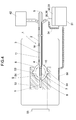
- a phantom experiment was practiced using the balloon catheter system according to the embodiment 1.
- a phantom 52 with a cylindrical cutout was left inside a bath 51 at 37 degrees C.
- Temperature sensors 53, 54 were put on upper and lower surfaces of the balloon 6, the electrode 7 for delivery of radiofrequency current was set inside the balloon 6, and the temperature sensor 8 was put at an end of the electrode 7 for delivery of radiofrequency current and in the vicinity of the distal end 5 of the inner tube 3 inside the balloon 6.
- an asymmetric vibrational wave W was applied from the external vibration generator 42 to the inside of the balloon 6 via the solution transport path 11 and then the inside of the balloon 6 was agitated by swirls S.
- numeral 55 denotes a thermometer for displaying temperatures detected by the temperature sensors 53, 54
- numeral 56 denotes a counter electrode externally provided to apply a radiofrequency current to the electrode 7 for delivery of radiofrequency current. The temperatures detected by the temperature sensors 53, 54 and the electrode temperature senor 10 were recorded with time.
- the temperature of the electrode 7 for delivery of radiofrequency current rose with the passage of time and reached 70 degrees C, while the upper and lower surface temperatures of the balloon 6 reached 60 degrees C.
- FIG. 6 shown is the relationship between the delivery time of radiofrequency current and a depth where the temperature of tissue showed 45 or more degrees C, when the surface temperature of the balloon 6 is 50 or 60 degrees C. Like this, the longer the delivery time, the deeper the depth where the temperature of tissue reached 45 degrees C at which the tissue becomes irreversibly damaged. Accordingly, it has been confirmed that by regulating the delivery time of radiofrequency current, an ablation depth was adjustable.
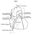
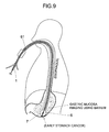
- the balloon 6 is allowed to contact with a periphery of an orifice of a pulmonary vein, being the origin of atrial fibrillation, from an inner surface of the vein to treat atrial fibrillation.
- an esophagus, phrenic nerves and abdominal vagus nerves exist in the vicinity of the heart and hence it is important that an atrial wall is ablated transmurally without injuring these internal organs and then the application of a radiofrequency current is interrupted.
- the thermal damage of the tissue becomes irreversible if subjected to the temperature of 45 or more degrees C and therefore it is important that the surface temperature of the balloon 6 is more precisely monitored and besides the delivery time of radiofrequency current is taken account of.
- the catheter shaft 1 is inserted from a femoral vein into a left atrium using a guide sheath 61 and the guide wire 12 and then the balloon 6 dilated by a mixed solution of physiologic saline and a contrast medium, which has been introduced from the solution transport path 11, is wedged into a pulmonary vein vestibule.
- a radiofrequency current to the electrode 7 for delivery of radiofrequency current inside the balloon 6
- an asymmetric vibrational wave W is fed from the vibration generator 42 to the inside of the balloon 6 via the solution transport path 11 to form swirls S.
- the temperature sensor 8 detects the temperature approximate to the surface temperature of the balloon 6, a radiofrequency output is increased until this temperature reaches a preset temperature.
- the surface temperature of the balloon 6 required to ablate tissue 60 to 65 degrees C are most suitable.
- a radiofrequency current is applied for 2 to 5 minutes depending on the thickness of an atrial wall measured by an intracardiac echo.
- a tissue depth is 2.3mm where its temperature reaches 45 degrees C as a result of the radiofrequency current application for 2 minutes, an application of the current for 3 minutes attains a 3.2mm depth and 5 minutes for 3.7mm depth.
- the safety can be enhanced by monitoring the maximum temperature inside the balloon 6 by means of the electrode temperature sensor 10.
- the inner tube 3 is stretched in relation to the outer tube 2 to contract the balloon 6, and then the catheter shaft 1 is extracted from the guide sheath 61 to check whether thrombus and fibrin are absent or not on the surface of the balloon 6. Ordinarily, if the surface temperature of the balloon 6 does not exceed 80 and 70 degrees C, respectively, these are absent.
- macrophages infiltrate underneath a thin atheromatous cap and release a lytic enzyme to lyse the atheromatous cap and hence the atheroma ruptures toward an intravascular lumen to cause an acute arterial occlusion, leading to myocardial infarction or cerebral infarction.
- an angioscope and an ultrasonic catheter are inserted into a vessel to observe a cross section of the vessel to picture the unstable plaque. Then, the catheter shaft 1 is inserted into the site of the unstable plaque to dilate the balloon 6, a vibration generator 42 is allowed to operate, and while a radiofrequency current is delivered under monitoring an approximate value of the surface temperature, detected by the temperature sensor 8, of the balloon 6.
- the temperature inside the atheromatosis near the atheromatous cap rises to 43 degrees C and then the application of a radiofrequency current for 2 minutes enables the macrophages to be annihilated. Then, an inflammatory reaction is slightly generated in the site due to heating to accelerate fibrosis and the atheromatous cap is thickened due to fibrous tissue, thus stabilizing the site of the lesion.
- a barium examination is performed to clarify the extent of the stomach cancer under fluoroscopy.
- a guide sheath 61 is inserted into the site of the stomach cancer through a nasal aperture or a mouth and then the catheter shaft 1 is inserted thereinto through the guide sheath 61.
- the balloon 6 is dilated by a mixed solution of a contrast medium and a physiological saline to be pressed against the site of the stomach cancer and then the balloon 6 is heated.
- the site is shallow, short-time heating is performed with the temperature inside the balloon 6 kept at 45 degrees C, while when deep, long-time heating is done with the higher temperature inside the balloon 6.
- the present invention is not limited to the above embodiments and various modifications are possible within the scope of the gist of the present invention.
- the form of the balloon e.g., is not limited to one described above and various forms may be applicable depending on the organ to be treated.
Landscapes
- Health & Medical Sciences (AREA)
- Surgery (AREA)
- Life Sciences & Earth Sciences (AREA)
- Engineering & Computer Science (AREA)
- Heart & Thoracic Surgery (AREA)
- Medical Informatics (AREA)
- Otolaryngology (AREA)
- Plasma & Fusion (AREA)
- Physics & Mathematics (AREA)
- Biomedical Technology (AREA)
- Cardiology (AREA)
- Nuclear Medicine, Radiotherapy & Molecular Imaging (AREA)
- Molecular Biology (AREA)
- Animal Behavior & Ethology (AREA)
- General Health & Medical Sciences (AREA)
- Public Health (AREA)
- Veterinary Medicine (AREA)
- Media Introduction/Drainage Providing Device (AREA)
- Surgical Instruments (AREA)
- Laser Surgery Devices (AREA)
Applications Claiming Priority (1)
| Application Number | Priority Date | Filing Date | Title |
|---|---|---|---|
| PCT/JP2008/073214 WO2010070766A1 (fr) | 2008-12-19 | 2008-12-19 | Système cathéter à ballon |
Publications (3)
| Publication Number | Publication Date |
|---|---|
| EP2382933A1 true EP2382933A1 (fr) | 2011-11-02 |
| EP2382933A4 EP2382933A4 (fr) | 2012-11-14 |
| EP2382933B1 EP2382933B1 (fr) | 2016-11-30 |
Family
ID=42268456
Family Applications (1)
| Application Number | Title | Priority Date | Filing Date |
|---|---|---|---|
| EP08878934.2A Active EP2382933B1 (fr) | 2008-12-19 | 2008-12-19 | Système cathéter à ballon |
Country Status (5)
| Country | Link |
|---|---|
| US (1) | US8647339B2 (fr) |
| EP (1) | EP2382933B1 (fr) |
| JP (1) | JP4988044B2 (fr) |
| CA (1) | CA2733241C (fr) |
| WO (1) | WO2010070766A1 (fr) |
Cited By (2)
| Publication number | Priority date | Publication date | Assignee | Title |
|---|---|---|---|---|
| EP2609884A1 (fr) * | 2011-12-26 | 2013-07-03 | Japan Electel Inc | Cathéter à ballonnet |
| CN106132328A (zh) * | 2014-10-15 | 2016-11-16 | 奥林巴斯株式会社 | 用于能量处置器具的控制装置以及能量处置系统 |
Families Citing this family (51)
| Publication number | Priority date | Publication date | Assignee | Title |
|---|---|---|---|---|
| US7756583B2 (en) | 2002-04-08 | 2010-07-13 | Ardian, Inc. | Methods and apparatus for intravascularly-induced neuromodulation |
| US8347891B2 (en) | 2002-04-08 | 2013-01-08 | Medtronic Ardian Luxembourg S.A.R.L. | Methods and apparatus for performing a non-continuous circumferential treatment of a body lumen |
| ES2564694T3 (es) | 2003-09-12 | 2016-03-28 | Vessix Vascular, Inc. | Sistema de remodelación y / o ablación excéntrica seleccionable de material ateroesclerótico |
| US8920414B2 (en) | 2004-09-10 | 2014-12-30 | Vessix Vascular, Inc. | Tuned RF energy and electrical tissue characterization for selective treatment of target tissues |
| US8396548B2 (en) | 2008-11-14 | 2013-03-12 | Vessix Vascular, Inc. | Selective drug delivery in a lumen |
| EP2438877B1 (fr) | 2005-03-28 | 2016-02-17 | Vessix Vascular, Inc. | Caractérisation électrique intraluminale de tissus et énergie RF réglée pour le traitement sélectif de l'athérome et d'autres tissus cibles |
| JP2009183312A (ja) * | 2006-07-14 | 2009-08-20 | Katsutoshi Tabuse | マイクロ波誘電加熱装置 |
| EP2076194B1 (fr) | 2006-10-18 | 2013-04-24 | Vessix Vascular, Inc. | Système pour induire des effets thermiques désirables sur un tissu anatomique |
| EP2076198A4 (fr) | 2006-10-18 | 2009-12-09 | Minnow Medical Inc | Induction d'effets souhaitables de température sur un tissu humain |
| US8496653B2 (en) | 2007-04-23 | 2013-07-30 | Boston Scientific Scimed, Inc. | Thrombus removal |
| US9561068B2 (en) | 2008-10-06 | 2017-02-07 | Virender K. Sharma | Method and apparatus for tissue ablation |
| CN104739502B (zh) | 2008-10-06 | 2018-01-19 | 维兰德·K·沙马 | 用于组织消融的方法和装置 |
| US9561066B2 (en) | 2008-10-06 | 2017-02-07 | Virender K. Sharma | Method and apparatus for tissue ablation |
| US10695126B2 (en) | 2008-10-06 | 2020-06-30 | Santa Anna Tech Llc | Catheter with a double balloon structure to generate and apply a heated ablative zone to tissue |
| US10064697B2 (en) | 2008-10-06 | 2018-09-04 | Santa Anna Tech Llc | Vapor based ablation system for treating various indications |
| JP5307900B2 (ja) | 2008-11-17 | 2013-10-02 | べシックス・バスキュラー・インコーポレイテッド | 組織トポグラフィの知識によらないエネルギーの選択的な蓄積 |
| JP5615508B2 (ja) * | 2009-03-31 | 2014-10-29 | 東レ株式会社 | 撹拌方法及びバルーン付きアブレーションカテーテルシステム |
| US8551096B2 (en) | 2009-05-13 | 2013-10-08 | Boston Scientific Scimed, Inc. | Directional delivery of energy and bioactives |
| CN103068330B (zh) | 2010-04-09 | 2016-06-29 | Vessix血管股份有限公司 | 用于治疗组织的功率发生和控制装置 |
| JP5759615B2 (ja) | 2011-04-08 | 2015-08-05 | コヴィディエン リミテッド パートナーシップ | 腎交感神経の除神経およびイオン導入薬物送達のためのイオン導入カテーテルシステムならびに方法 |
| US10610294B2 (en) | 2012-04-22 | 2020-04-07 | Newuro, B.V. | Devices and methods for transurethral bladder partitioning |
| US9883906B2 (en) | 2012-04-22 | 2018-02-06 | Newuro, B.V. | Bladder tissue modification for overactive bladder disorders |
| KR101415900B1 (ko) * | 2012-05-18 | 2014-07-08 | 신경민 | 고주파 열치료용 중첩형 바이폴라 전극 |
| JP5500273B1 (ja) * | 2012-07-05 | 2014-05-21 | 有限会社日本エレクテル | バルーンカテーテルシステム |
| US10342608B2 (en) | 2012-10-18 | 2019-07-09 | The Board Of Trustees Of The Leland Stanford Junior University | Ablation catheter system and method for deploying same |
| EP2945556A4 (fr) | 2013-01-17 | 2016-08-31 | Virender K Sharma | Procédé et appareil d'ablation de tissu |
| US10709490B2 (en) | 2014-05-07 | 2020-07-14 | Medtronic Ardian Luxembourg S.A.R.L. | Catheter assemblies comprising a direct heating element for renal neuromodulation and associated systems and methods |
| JP6246143B2 (ja) * | 2015-02-13 | 2017-12-13 | 有限会社日本エレクテル | バルーンカテーテルアブレーションシステム |
| US10342611B2 (en) | 2015-04-29 | 2019-07-09 | Innoblative Designs, Inc. | Cavitary tissue ablation |
| CA3234408A1 (fr) | 2015-05-12 | 2016-11-17 | National University Of Ireland Galway | Dispositifs pour la neuromodulation nasale therapeutique et procedes et systemes associes |
| US12207863B2 (en) | 2015-10-29 | 2025-01-28 | Innoblative Designs, Inc. | Screen sphere tissue ablation devices and methods |
| WO2017075366A1 (fr) | 2015-10-29 | 2017-05-04 | Innoblative Designs, Inc. | Dispositifs d'ablation de tissu à tamis sphérique et procédés associés |
| WO2017104023A1 (fr) * | 2015-12-16 | 2017-06-22 | 有限会社日本エレクテル | Système de cathéter à ballonnet à haute fréquence |
| WO2017136262A1 (fr) | 2016-02-02 | 2017-08-10 | Innoblative Designs, Inc. | Système d'ablation de tissu cavitaire |
| WO2017151431A1 (fr) | 2016-03-01 | 2017-09-08 | Innoblative Designs, Inc. | Résection et coagulation de tissu |
| US12364537B2 (en) | 2016-05-02 | 2025-07-22 | Santa Anna Tech Llc | Catheter with a double balloon structure to generate and apply a heated ablative zone to tissue |
| US11331140B2 (en) | 2016-05-19 | 2022-05-17 | Aqua Heart, Inc. | Heated vapor ablation systems and methods for treating cardiac conditions |
| JP2019536509A (ja) | 2016-10-17 | 2019-12-19 | イノブレイティブ デザインズ, インコーポレイテッド | 処置デバイスおよび方法 |
| JP6875757B2 (ja) | 2016-11-08 | 2021-05-26 | イノブレイティブ デザインズ, インコーポレイテッド | 電気手術の組織および脈管シールデバイス |
| US12414814B2 (en) | 2016-12-15 | 2025-09-16 | St. Jude Medical, Cardiology Division, Inc. | Pulmonary vein isolation balloon catheter |
| JP7033142B2 (ja) | 2017-01-06 | 2022-03-09 | セント・ジュード・メディカル,カーディオロジー・ディヴィジョン,インコーポレイテッド | 肺静脈隔離バルーンカテーテル |
| US10912609B2 (en) | 2017-01-06 | 2021-02-09 | St. Jude Medical, Cardiology Division, Inc. | Pulmonary vein isolation balloon catheter |
| US11786297B2 (en) | 2017-07-26 | 2023-10-17 | Innoblative Designs, Inc. | Minimally invasive articulating assembly having ablation capabilities |
| AU2019207630B2 (en) * | 2018-01-10 | 2021-08-12 | Adagio Medical, Inc. | Device for monitoring temperatures within and adjacent to body lumens |
| US20240398462A1 (en) | 2018-06-01 | 2024-12-05 | Aqua Medical, Inc. | Duodenal Ablation with Improved Depth and Consistency of Ablation |
| WO2019232432A1 (fr) | 2018-06-01 | 2019-12-05 | Santa Anna Tech Llc | Procédés de traitement d'ablation à base de vapeur à plusieurs étapes et systèmes de génération et de distribution de vapeur |
| TW202203860A (zh) * | 2020-03-31 | 2022-02-01 | 日商東麗股份有限公司 | 附有氣球之電燒導管系統及其控制方法 |
| WO2021201078A1 (fr) * | 2020-03-31 | 2021-10-07 | 東レ株式会社 | Cathéter à ballonnet et système de cathéter à ballonnet |
| JPWO2022211010A1 (fr) * | 2021-03-31 | 2022-10-06 | ||
| US12527622B2 (en) | 2021-04-26 | 2026-01-20 | Innoblative Designs, Inc. | System for minimally invasive tissue ablation and sealing |
| JPWO2023080147A1 (fr) * | 2021-11-04 | 2023-05-11 |
Family Cites Families (12)
| Publication number | Priority date | Publication date | Assignee | Title |
|---|---|---|---|---|
| FR2639238B1 (fr) * | 1988-11-21 | 1991-02-22 | Technomed Int Sa | Appareil de traitement chirurgical de tissus par hyperthermie, de preference la prostate, comprenant des moyens de protection thermique comprenant de preference des moyens formant ecran radioreflechissant |
| US6620188B1 (en) | 1998-08-24 | 2003-09-16 | Radiant Medical, Inc. | Methods and apparatus for regional and whole body temperature modification |
| US5451220A (en) * | 1994-08-15 | 1995-09-19 | Microsonic Engineering Devices Company, Inc. | Battery operated multifunction ultrasonic wire for angioplasty |
| JP3607231B2 (ja) | 2001-09-28 | 2005-01-05 | 有限会社日本エレクテル | 高周波加温バルーンカテーテル |
| US6929639B2 (en) * | 2002-08-30 | 2005-08-16 | Scimed Life Systems, Inc. | Cryo ablation coil |
| JP3771553B2 (ja) * | 2003-09-02 | 2006-04-26 | 平河ヒューテック株式会社 | 化学検査装置 |
| JP4391221B2 (ja) | 2003-12-22 | 2009-12-24 | 有限会社日本エレクテル | 高周波加温バルーンカテーテル |
| JP2006198209A (ja) * | 2005-01-21 | 2006-08-03 | Toray Ind Inc | バルーン付きアブレーションカテーテル |
| JP2006239234A (ja) * | 2005-03-04 | 2006-09-14 | Toray Ind Inc | バルーンカテーテルおよびその製造方法 |
| WO2007052341A1 (fr) * | 2005-11-01 | 2007-05-10 | Japan Electel Inc. | Systeme de catheter a ballonnet |
| JP4226040B2 (ja) | 2007-01-12 | 2009-02-18 | 有限会社日本エレクテル | 高周波加温バルーンカテーテルシステム |
| JP2009034448A (ja) * | 2007-08-03 | 2009-02-19 | Nihon Medix | 加熱式バルーンカテーテル装置におけるピンホール検出装置およびピンホール検出用ユニット |
-
2008
- 2008-12-19 CA CA2733241A patent/CA2733241C/fr active Active
- 2008-12-19 US US12/921,595 patent/US8647339B2/en active Active
- 2008-12-19 EP EP08878934.2A patent/EP2382933B1/fr active Active
- 2008-12-19 WO PCT/JP2008/073214 patent/WO2010070766A1/fr not_active Ceased
- 2008-12-19 JP JP2010527684A patent/JP4988044B2/ja active Active
Cited By (3)
| Publication number | Priority date | Publication date | Assignee | Title |
|---|---|---|---|---|
| EP2609884A1 (fr) * | 2011-12-26 | 2013-07-03 | Japan Electel Inc | Cathéter à ballonnet |
| CN106132328A (zh) * | 2014-10-15 | 2016-11-16 | 奥林巴斯株式会社 | 用于能量处置器具的控制装置以及能量处置系统 |
| CN106132328B (zh) * | 2014-10-15 | 2019-01-01 | 奥林巴斯株式会社 | 用于能量处置器具的控制装置以及能量处置系统 |
Also Published As
| Publication number | Publication date |
|---|---|
| US20110264085A1 (en) | 2011-10-27 |
| WO2010070766A1 (fr) | 2010-06-24 |
| EP2382933A4 (fr) | 2012-11-14 |
| CA2733241A1 (fr) | 2010-06-24 |
| JP4988044B2 (ja) | 2012-08-01 |
| CA2733241C (fr) | 2016-08-16 |
| JPWO2010070766A1 (ja) | 2012-05-24 |
| US8647339B2 (en) | 2014-02-11 |
| EP2382933B1 (fr) | 2016-11-30 |
Similar Documents
| Publication | Publication Date | Title |
|---|---|---|
| CA2733241C (fr) | Systeme catheter a ballon | |
| JP6571217B2 (ja) | 医療装置 | |
| JP7238034B2 (ja) | 温度制御された短時間アブレーション | |
| US10973575B2 (en) | Temperature controlled short duration ablation | |
| CN106994043B (zh) | 温度受控的短持续时间消融 | |
| CN107019553B (zh) | 温度受控的短持续时间消融 | |
| US12575876B2 (en) | Device for tissue treatment and method for electrode positioning | |
| CN111870338B (zh) | 用于利用电阻加热的温度受控的短持续时间消融的设备 | |
| JP2005192725A (ja) | バルーン付きアブレーションカテーテル |
Legal Events
| Date | Code | Title | Description |
|---|---|---|---|
| PUAI | Public reference made under article 153(3) epc to a published international application that has entered the european phase |
Free format text: ORIGINAL CODE: 0009012 |
|
| 17P | Request for examination filed |
Effective date: 20110719 |
|
| AK | Designated contracting states |
Kind code of ref document: A1 Designated state(s): AT BE BG CH CY CZ DE DK EE ES FI FR GB GR HR HU IE IS IT LI LT LU LV MC MT NL NO PL PT RO SE SI SK TR |
|
| DAX | Request for extension of the european patent (deleted) | ||
| A4 | Supplementary search report drawn up and despatched |
Effective date: 20121015 |
|
| RIC1 | Information provided on ipc code assigned before grant |
Ipc: A61B 18/12 20060101AFI20121009BHEP |
|
| GRAP | Despatch of communication of intention to grant a patent |
Free format text: ORIGINAL CODE: EPIDOSNIGR1 |
|
| INTG | Intention to grant announced |
Effective date: 20160622 |
|
| GRAS | Grant fee paid |
Free format text: ORIGINAL CODE: EPIDOSNIGR3 |
|
| GRAA | (expected) grant |
Free format text: ORIGINAL CODE: 0009210 |
|
| AK | Designated contracting states |
Kind code of ref document: B1 Designated state(s): AT BE BG CH CY CZ DE DK EE ES FI FR GB GR HR HU IE IS IT LI LT LU LV MC MT NL NO PL PT RO SE SI SK TR |
|
| REG | Reference to a national code |
Ref country code: CH Ref legal event code: EP Ref country code: GB Ref legal event code: FG4D |
|
| REG | Reference to a national code |
Ref country code: AT Ref legal event code: REF Ref document number: 849077 Country of ref document: AT Kind code of ref document: T Effective date: 20161215 |
|
| REG | Reference to a national code |
Ref country code: IE Ref legal event code: FG4D Ref country code: FR Ref legal event code: PLFP Year of fee payment: 9 |
|
| REG | Reference to a national code |
Ref country code: DE Ref legal event code: R096 Ref document number: 602008047712 Country of ref document: DE |
|
| PG25 | Lapsed in a contracting state [announced via postgrant information from national office to epo] |
Ref country code: LV Free format text: LAPSE BECAUSE OF FAILURE TO SUBMIT A TRANSLATION OF THE DESCRIPTION OR TO PAY THE FEE WITHIN THE PRESCRIBED TIME-LIMIT Effective date: 20161130 |
|
| REG | Reference to a national code |
Ref country code: LT Ref legal event code: MG4D |
|
| REG | Reference to a national code |
Ref country code: NL Ref legal event code: MP Effective date: 20161130 |
|
| REG | Reference to a national code |
Ref country code: AT Ref legal event code: MK05 Ref document number: 849077 Country of ref document: AT Kind code of ref document: T Effective date: 20161130 |
|
| PG25 | Lapsed in a contracting state [announced via postgrant information from national office to epo] |
Ref country code: NO Free format text: LAPSE BECAUSE OF FAILURE TO SUBMIT A TRANSLATION OF THE DESCRIPTION OR TO PAY THE FEE WITHIN THE PRESCRIBED TIME-LIMIT Effective date: 20170228 Ref country code: SE Free format text: LAPSE BECAUSE OF FAILURE TO SUBMIT A TRANSLATION OF THE DESCRIPTION OR TO PAY THE FEE WITHIN THE PRESCRIBED TIME-LIMIT Effective date: 20161130 Ref country code: GR Free format text: LAPSE BECAUSE OF FAILURE TO SUBMIT A TRANSLATION OF THE DESCRIPTION OR TO PAY THE FEE WITHIN THE PRESCRIBED TIME-LIMIT Effective date: 20170301 Ref country code: LT Free format text: LAPSE BECAUSE OF FAILURE TO SUBMIT A TRANSLATION OF THE DESCRIPTION OR TO PAY THE FEE WITHIN THE PRESCRIBED TIME-LIMIT Effective date: 20161130 |
|
| PG25 | Lapsed in a contracting state [announced via postgrant information from national office to epo] |
Ref country code: PL Free format text: LAPSE BECAUSE OF FAILURE TO SUBMIT A TRANSLATION OF THE DESCRIPTION OR TO PAY THE FEE WITHIN THE PRESCRIBED TIME-LIMIT Effective date: 20161130 Ref country code: PT Free format text: LAPSE BECAUSE OF FAILURE TO SUBMIT A TRANSLATION OF THE DESCRIPTION OR TO PAY THE FEE WITHIN THE PRESCRIBED TIME-LIMIT Effective date: 20170330 Ref country code: FI Free format text: LAPSE BECAUSE OF FAILURE TO SUBMIT A TRANSLATION OF THE DESCRIPTION OR TO PAY THE FEE WITHIN THE PRESCRIBED TIME-LIMIT Effective date: 20161130 Ref country code: HR Free format text: LAPSE BECAUSE OF FAILURE TO SUBMIT A TRANSLATION OF THE DESCRIPTION OR TO PAY THE FEE WITHIN THE PRESCRIBED TIME-LIMIT Effective date: 20161130 Ref country code: BE Free format text: LAPSE BECAUSE OF NON-PAYMENT OF DUE FEES Effective date: 20161231 Ref country code: AT Free format text: LAPSE BECAUSE OF FAILURE TO SUBMIT A TRANSLATION OF THE DESCRIPTION OR TO PAY THE FEE WITHIN THE PRESCRIBED TIME-LIMIT Effective date: 20161130 Ref country code: ES Free format text: LAPSE BECAUSE OF FAILURE TO SUBMIT A TRANSLATION OF THE DESCRIPTION OR TO PAY THE FEE WITHIN THE PRESCRIBED TIME-LIMIT Effective date: 20161130 |
|
| PG25 | Lapsed in a contracting state [announced via postgrant information from national office to epo] |
Ref country code: NL Free format text: LAPSE BECAUSE OF FAILURE TO SUBMIT A TRANSLATION OF THE DESCRIPTION OR TO PAY THE FEE WITHIN THE PRESCRIBED TIME-LIMIT Effective date: 20161130 |
|
| PG25 | Lapsed in a contracting state [announced via postgrant information from national office to epo] |
Ref country code: DK Free format text: LAPSE BECAUSE OF FAILURE TO SUBMIT A TRANSLATION OF THE DESCRIPTION OR TO PAY THE FEE WITHIN THE PRESCRIBED TIME-LIMIT Effective date: 20161130 Ref country code: EE Free format text: LAPSE BECAUSE OF FAILURE TO SUBMIT A TRANSLATION OF THE DESCRIPTION OR TO PAY THE FEE WITHIN THE PRESCRIBED TIME-LIMIT Effective date: 20161130 Ref country code: RO Free format text: LAPSE BECAUSE OF FAILURE TO SUBMIT A TRANSLATION OF THE DESCRIPTION OR TO PAY THE FEE WITHIN THE PRESCRIBED TIME-LIMIT Effective date: 20161130 Ref country code: SK Free format text: LAPSE BECAUSE OF FAILURE TO SUBMIT A TRANSLATION OF THE DESCRIPTION OR TO PAY THE FEE WITHIN THE PRESCRIBED TIME-LIMIT Effective date: 20161130 Ref country code: CZ Free format text: LAPSE BECAUSE OF FAILURE TO SUBMIT A TRANSLATION OF THE DESCRIPTION OR TO PAY THE FEE WITHIN THE PRESCRIBED TIME-LIMIT Effective date: 20161130 |
|
| REG | Reference to a national code |
Ref country code: CH Ref legal event code: PL |
|
| PG25 | Lapsed in a contracting state [announced via postgrant information from national office to epo] |
Ref country code: BE Free format text: LAPSE BECAUSE OF FAILURE TO SUBMIT A TRANSLATION OF THE DESCRIPTION OR TO PAY THE FEE WITHIN THE PRESCRIBED TIME-LIMIT Effective date: 20161130 Ref country code: BG Free format text: LAPSE BECAUSE OF FAILURE TO SUBMIT A TRANSLATION OF THE DESCRIPTION OR TO PAY THE FEE WITHIN THE PRESCRIBED TIME-LIMIT Effective date: 20170228 |
|
| REG | Reference to a national code |
Ref country code: DE Ref legal event code: R097 Ref document number: 602008047712 Country of ref document: DE |
|
| PG25 | Lapsed in a contracting state [announced via postgrant information from national office to epo] |
Ref country code: MC Free format text: LAPSE BECAUSE OF FAILURE TO SUBMIT A TRANSLATION OF THE DESCRIPTION OR TO PAY THE FEE WITHIN THE PRESCRIBED TIME-LIMIT Effective date: 20161130 |
|
| REG | Reference to a national code |
Ref country code: IE Ref legal event code: MM4A |
|
| PLBE | No opposition filed within time limit |
Free format text: ORIGINAL CODE: 0009261 |
|
| STAA | Information on the status of an ep patent application or granted ep patent |
Free format text: STATUS: NO OPPOSITION FILED WITHIN TIME LIMIT |
|
| PG25 | Lapsed in a contracting state [announced via postgrant information from national office to epo] |
Ref country code: LI Free format text: LAPSE BECAUSE OF NON-PAYMENT OF DUE FEES Effective date: 20161231 Ref country code: LU Free format text: LAPSE BECAUSE OF NON-PAYMENT OF DUE FEES Effective date: 20161219 Ref country code: CH Free format text: LAPSE BECAUSE OF NON-PAYMENT OF DUE FEES Effective date: 20161231 |
|
| 26N | No opposition filed |
Effective date: 20170831 |
|
| PG25 | Lapsed in a contracting state [announced via postgrant information from national office to epo] |
Ref country code: IE Free format text: LAPSE BECAUSE OF NON-PAYMENT OF DUE FEES Effective date: 20161219 Ref country code: SI Free format text: LAPSE BECAUSE OF FAILURE TO SUBMIT A TRANSLATION OF THE DESCRIPTION OR TO PAY THE FEE WITHIN THE PRESCRIBED TIME-LIMIT Effective date: 20161130 |
|
| REG | Reference to a national code |
Ref country code: FR Ref legal event code: PLFP Year of fee payment: 10 |
|
| PG25 | Lapsed in a contracting state [announced via postgrant information from national office to epo] |
Ref country code: HU Free format text: LAPSE BECAUSE OF FAILURE TO SUBMIT A TRANSLATION OF THE DESCRIPTION OR TO PAY THE FEE WITHIN THE PRESCRIBED TIME-LIMIT; INVALID AB INITIO Effective date: 20081219 Ref country code: CY Free format text: LAPSE BECAUSE OF FAILURE TO SUBMIT A TRANSLATION OF THE DESCRIPTION OR TO PAY THE FEE WITHIN THE PRESCRIBED TIME-LIMIT Effective date: 20161130 |
|
| PG25 | Lapsed in a contracting state [announced via postgrant information from national office to epo] |
Ref country code: TR Free format text: LAPSE BECAUSE OF FAILURE TO SUBMIT A TRANSLATION OF THE DESCRIPTION OR TO PAY THE FEE WITHIN THE PRESCRIBED TIME-LIMIT Effective date: 20161130 Ref country code: IS Free format text: LAPSE BECAUSE OF FAILURE TO SUBMIT A TRANSLATION OF THE DESCRIPTION OR TO PAY THE FEE WITHIN THE PRESCRIBED TIME-LIMIT Effective date: 20161130 |
|
| REG | Reference to a national code |
Ref country code: FR Ref legal event code: PLFP Year of fee payment: 11 |
|
| PG25 | Lapsed in a contracting state [announced via postgrant information from national office to epo] |
Ref country code: MT Free format text: LAPSE BECAUSE OF NON-PAYMENT OF DUE FEES Effective date: 20161219 |
|
| PGFP | Annual fee paid to national office [announced via postgrant information from national office to epo] |
Ref country code: DE Payment date: 20251211 Year of fee payment: 18 |
|
| PGFP | Annual fee paid to national office [announced via postgrant information from national office to epo] |
Ref country code: GB Payment date: 20251219 Year of fee payment: 18 |
|
| PGFP | Annual fee paid to national office [announced via postgrant information from national office to epo] |
Ref country code: IT Payment date: 20251223 Year of fee payment: 18 |
|
| PGFP | Annual fee paid to national office [announced via postgrant information from national office to epo] |
Ref country code: FR Payment date: 20251222 Year of fee payment: 18 |