EP2383140A1 - Dispositif de transmission de puissance pour véhicule hybride - Google Patents
Dispositif de transmission de puissance pour véhicule hybride Download PDFInfo
- Publication number
- EP2383140A1 EP2383140A1 EP09825891A EP09825891A EP2383140A1 EP 2383140 A1 EP2383140 A1 EP 2383140A1 EP 09825891 A EP09825891 A EP 09825891A EP 09825891 A EP09825891 A EP 09825891A EP 2383140 A1 EP2383140 A1 EP 2383140A1
- Authority
- EP
- European Patent Office
- Prior art keywords
- motor
- engine
- clutch means
- power transmitting
- vehicle
- Prior art date
- Legal status (The legal status is an assumption and is not a legal conclusion. Google has not performed a legal analysis and makes no representation as to the accuracy of the status listed.)
- Granted
Links
Images










Classifications
-
- B—PERFORMING OPERATIONS; TRANSPORTING
- B60—VEHICLES IN GENERAL
- B60W—CONJOINT CONTROL OF VEHICLE SUB-UNITS OF DIFFERENT TYPE OR DIFFERENT FUNCTION; CONTROL SYSTEMS SPECIALLY ADAPTED FOR HYBRID VEHICLES; ROAD VEHICLE DRIVE CONTROL SYSTEMS FOR PURPOSES NOT RELATED TO THE CONTROL OF A PARTICULAR SUB-UNIT
- B60W20/00—Control systems specially adapted for hybrid vehicles
- B60W20/10—Controlling the power contribution of each of the prime movers to meet required power demand
- B60W20/15—Control strategies specially adapted for achieving a particular effect
-
- B—PERFORMING OPERATIONS; TRANSPORTING
- B60—VEHICLES IN GENERAL
- B60K—ARRANGEMENT OR MOUNTING OF PROPULSION UNITS OR OF TRANSMISSIONS IN VEHICLES; ARRANGEMENT OR MOUNTING OF PLURAL DIVERSE PRIME-MOVERS IN VEHICLES; AUXILIARY DRIVES FOR VEHICLES; INSTRUMENTATION OR DASHBOARDS FOR VEHICLES; ARRANGEMENTS IN CONNECTION WITH COOLING, AIR INTAKE, GAS EXHAUST OR FUEL SUPPLY OF PROPULSION UNITS IN VEHICLES
- B60K6/00—Arrangement or mounting of plural diverse prime-movers for mutual or common propulsion, e.g. hybrid propulsion systems comprising electric motors and internal combustion engines
- B60K6/20—Arrangement or mounting of plural diverse prime-movers for mutual or common propulsion, e.g. hybrid propulsion systems comprising electric motors and internal combustion engines the prime-movers consisting of electric motors and internal combustion engines, e.g. HEVs
- B60K6/22—Arrangement or mounting of plural diverse prime-movers for mutual or common propulsion, e.g. hybrid propulsion systems comprising electric motors and internal combustion engines the prime-movers consisting of electric motors and internal combustion engines, e.g. HEVs characterised by apparatus, components or means specially adapted for HEVs
- B60K6/38—Arrangement or mounting of plural diverse prime-movers for mutual or common propulsion, e.g. hybrid propulsion systems comprising electric motors and internal combustion engines the prime-movers consisting of electric motors and internal combustion engines, e.g. HEVs characterised by apparatus, components or means specially adapted for HEVs characterised by the driveline clutches
- B60K6/387—Actuated clutches, i.e. clutches engaged or disengaged by electric, hydraulic or mechanical actuating means
-
- B—PERFORMING OPERATIONS; TRANSPORTING
- B60—VEHICLES IN GENERAL
- B60K—ARRANGEMENT OR MOUNTING OF PROPULSION UNITS OR OF TRANSMISSIONS IN VEHICLES; ARRANGEMENT OR MOUNTING OF PLURAL DIVERSE PRIME-MOVERS IN VEHICLES; AUXILIARY DRIVES FOR VEHICLES; INSTRUMENTATION OR DASHBOARDS FOR VEHICLES; ARRANGEMENTS IN CONNECTION WITH COOLING, AIR INTAKE, GAS EXHAUST OR FUEL SUPPLY OF PROPULSION UNITS IN VEHICLES
- B60K6/00—Arrangement or mounting of plural diverse prime-movers for mutual or common propulsion, e.g. hybrid propulsion systems comprising electric motors and internal combustion engines
- B60K6/20—Arrangement or mounting of plural diverse prime-movers for mutual or common propulsion, e.g. hybrid propulsion systems comprising electric motors and internal combustion engines the prime-movers consisting of electric motors and internal combustion engines, e.g. HEVs
- B60K6/22—Arrangement or mounting of plural diverse prime-movers for mutual or common propulsion, e.g. hybrid propulsion systems comprising electric motors and internal combustion engines the prime-movers consisting of electric motors and internal combustion engines, e.g. HEVs characterised by apparatus, components or means specially adapted for HEVs
- B60K6/40—Arrangement or mounting of plural diverse prime-movers for mutual or common propulsion, e.g. hybrid propulsion systems comprising electric motors and internal combustion engines the prime-movers consisting of electric motors and internal combustion engines, e.g. HEVs characterised by apparatus, components or means specially adapted for HEVs characterised by the assembly or relative disposition of components
-
- B—PERFORMING OPERATIONS; TRANSPORTING
- B60—VEHICLES IN GENERAL
- B60K—ARRANGEMENT OR MOUNTING OF PROPULSION UNITS OR OF TRANSMISSIONS IN VEHICLES; ARRANGEMENT OR MOUNTING OF PLURAL DIVERSE PRIME-MOVERS IN VEHICLES; AUXILIARY DRIVES FOR VEHICLES; INSTRUMENTATION OR DASHBOARDS FOR VEHICLES; ARRANGEMENTS IN CONNECTION WITH COOLING, AIR INTAKE, GAS EXHAUST OR FUEL SUPPLY OF PROPULSION UNITS IN VEHICLES
- B60K6/00—Arrangement or mounting of plural diverse prime-movers for mutual or common propulsion, e.g. hybrid propulsion systems comprising electric motors and internal combustion engines
- B60K6/20—Arrangement or mounting of plural diverse prime-movers for mutual or common propulsion, e.g. hybrid propulsion systems comprising electric motors and internal combustion engines the prime-movers consisting of electric motors and internal combustion engines, e.g. HEVs
- B60K6/42—Arrangement or mounting of plural diverse prime-movers for mutual or common propulsion, e.g. hybrid propulsion systems comprising electric motors and internal combustion engines the prime-movers consisting of electric motors and internal combustion engines, e.g. HEVs characterised by the architecture of the hybrid electric vehicle
- B60K6/48—Parallel type
-
- B—PERFORMING OPERATIONS; TRANSPORTING
- B60—VEHICLES IN GENERAL
- B60K—ARRANGEMENT OR MOUNTING OF PROPULSION UNITS OR OF TRANSMISSIONS IN VEHICLES; ARRANGEMENT OR MOUNTING OF PLURAL DIVERSE PRIME-MOVERS IN VEHICLES; AUXILIARY DRIVES FOR VEHICLES; INSTRUMENTATION OR DASHBOARDS FOR VEHICLES; ARRANGEMENTS IN CONNECTION WITH COOLING, AIR INTAKE, GAS EXHAUST OR FUEL SUPPLY OF PROPULSION UNITS IN VEHICLES
- B60K6/00—Arrangement or mounting of plural diverse prime-movers for mutual or common propulsion, e.g. hybrid propulsion systems comprising electric motors and internal combustion engines
- B60K6/20—Arrangement or mounting of plural diverse prime-movers for mutual or common propulsion, e.g. hybrid propulsion systems comprising electric motors and internal combustion engines the prime-movers consisting of electric motors and internal combustion engines, e.g. HEVs
- B60K6/50—Architecture of the driveline characterised by arrangement or kind of transmission units
- B60K6/54—Transmission for changing ratio
- B60K6/543—Transmission for changing ratio the transmission being a continuously variable transmission
-
- B—PERFORMING OPERATIONS; TRANSPORTING
- B60—VEHICLES IN GENERAL
- B60K—ARRANGEMENT OR MOUNTING OF PROPULSION UNITS OR OF TRANSMISSIONS IN VEHICLES; ARRANGEMENT OR MOUNTING OF PLURAL DIVERSE PRIME-MOVERS IN VEHICLES; AUXILIARY DRIVES FOR VEHICLES; INSTRUMENTATION OR DASHBOARDS FOR VEHICLES; ARRANGEMENTS IN CONNECTION WITH COOLING, AIR INTAKE, GAS EXHAUST OR FUEL SUPPLY OF PROPULSION UNITS IN VEHICLES
- B60K6/00—Arrangement or mounting of plural diverse prime-movers for mutual or common propulsion, e.g. hybrid propulsion systems comprising electric motors and internal combustion engines
- B60K6/20—Arrangement or mounting of plural diverse prime-movers for mutual or common propulsion, e.g. hybrid propulsion systems comprising electric motors and internal combustion engines the prime-movers consisting of electric motors and internal combustion engines, e.g. HEVs
- B60K6/50—Architecture of the driveline characterised by arrangement or kind of transmission units
- B60K6/54—Transmission for changing ratio
- B60K6/547—Transmission for changing ratio the transmission being a stepped gearing
-
- B—PERFORMING OPERATIONS; TRANSPORTING
- B60—VEHICLES IN GENERAL
- B60L—PROPULSION OF ELECTRICALLY-PROPELLED VEHICLES; SUPPLYING ELECTRIC POWER FOR AUXILIARY EQUIPMENT OF ELECTRICALLY-PROPELLED VEHICLES; ELECTRODYNAMIC BRAKE SYSTEMS FOR VEHICLES IN GENERAL; MAGNETIC SUSPENSION OR LEVITATION FOR VEHICLES; MONITORING OPERATING VARIABLES OF ELECTRICALLY-PROPELLED VEHICLES; ELECTRIC SAFETY DEVICES FOR ELECTRICALLY-PROPELLED VEHICLES
- B60L50/00—Electric propulsion with power supplied within the vehicle
- B60L50/10—Electric propulsion with power supplied within the vehicle using propulsion power supplied by engine-driven generators, e.g. generators driven by combustion engines
- B60L50/16—Electric propulsion with power supplied within the vehicle using propulsion power supplied by engine-driven generators, e.g. generators driven by combustion engines with provision for separate direct mechanical propulsion
-
- B—PERFORMING OPERATIONS; TRANSPORTING
- B60—VEHICLES IN GENERAL
- B60W—CONJOINT CONTROL OF VEHICLE SUB-UNITS OF DIFFERENT TYPE OR DIFFERENT FUNCTION; CONTROL SYSTEMS SPECIALLY ADAPTED FOR HYBRID VEHICLES; ROAD VEHICLE DRIVE CONTROL SYSTEMS FOR PURPOSES NOT RELATED TO THE CONTROL OF A PARTICULAR SUB-UNIT
- B60W10/00—Conjoint control of vehicle sub-units of different type or different function
- B60W10/02—Conjoint control of vehicle sub-units of different type or different function including control of driveline clutches
-
- B—PERFORMING OPERATIONS; TRANSPORTING
- B60—VEHICLES IN GENERAL
- B60W—CONJOINT CONTROL OF VEHICLE SUB-UNITS OF DIFFERENT TYPE OR DIFFERENT FUNCTION; CONTROL SYSTEMS SPECIALLY ADAPTED FOR HYBRID VEHICLES; ROAD VEHICLE DRIVE CONTROL SYSTEMS FOR PURPOSES NOT RELATED TO THE CONTROL OF A PARTICULAR SUB-UNIT
- B60W10/00—Conjoint control of vehicle sub-units of different type or different function
- B60W10/04—Conjoint control of vehicle sub-units of different type or different function including control of propulsion units
- B60W10/08—Conjoint control of vehicle sub-units of different type or different function including control of propulsion units including control of electric propulsion units, e.g. motors or generators
-
- B—PERFORMING OPERATIONS; TRANSPORTING
- B60—VEHICLES IN GENERAL
- B60W—CONJOINT CONTROL OF VEHICLE SUB-UNITS OF DIFFERENT TYPE OR DIFFERENT FUNCTION; CONTROL SYSTEMS SPECIALLY ADAPTED FOR HYBRID VEHICLES; ROAD VEHICLE DRIVE CONTROL SYSTEMS FOR PURPOSES NOT RELATED TO THE CONTROL OF A PARTICULAR SUB-UNIT
- B60W10/00—Conjoint control of vehicle sub-units of different type or different function
- B60W10/10—Conjoint control of vehicle sub-units of different type or different function including control of change-speed gearings
- B60W10/11—Stepped gearings
- B60W10/113—Stepped gearings with two input flow paths, e.g. double clutch transmission selection of one of the torque flow paths by the corresponding input clutch
-
- B—PERFORMING OPERATIONS; TRANSPORTING
- B60—VEHICLES IN GENERAL
- B60W—CONJOINT CONTROL OF VEHICLE SUB-UNITS OF DIFFERENT TYPE OR DIFFERENT FUNCTION; CONTROL SYSTEMS SPECIALLY ADAPTED FOR HYBRID VEHICLES; ROAD VEHICLE DRIVE CONTROL SYSTEMS FOR PURPOSES NOT RELATED TO THE CONTROL OF A PARTICULAR SUB-UNIT
- B60W30/00—Purposes of road vehicle drive control systems not related to the control of a particular sub-unit, e.g. of systems using conjoint control of vehicle sub-units
- B60W30/18—Propelling the vehicle
- B60W30/18009—Propelling the vehicle related to particular drive situations
- B60W30/18054—Propelling the vehicle related to particular drive situations at stand still, e.g. engine in idling state
-
- B—PERFORMING OPERATIONS; TRANSPORTING
- B60—VEHICLES IN GENERAL
- B60L—PROPULSION OF ELECTRICALLY-PROPELLED VEHICLES; SUPPLYING ELECTRIC POWER FOR AUXILIARY EQUIPMENT OF ELECTRICALLY-PROPELLED VEHICLES; ELECTRODYNAMIC BRAKE SYSTEMS FOR VEHICLES IN GENERAL; MAGNETIC SUSPENSION OR LEVITATION FOR VEHICLES; MONITORING OPERATING VARIABLES OF ELECTRICALLY-PROPELLED VEHICLES; ELECTRIC SAFETY DEVICES FOR ELECTRICALLY-PROPELLED VEHICLES
- B60L2210/00—Converter types
- B60L2210/20—AC to AC converters
-
- B—PERFORMING OPERATIONS; TRANSPORTING
- B60—VEHICLES IN GENERAL
- B60L—PROPULSION OF ELECTRICALLY-PROPELLED VEHICLES; SUPPLYING ELECTRIC POWER FOR AUXILIARY EQUIPMENT OF ELECTRICALLY-PROPELLED VEHICLES; ELECTRODYNAMIC BRAKE SYSTEMS FOR VEHICLES IN GENERAL; MAGNETIC SUSPENSION OR LEVITATION FOR VEHICLES; MONITORING OPERATING VARIABLES OF ELECTRICALLY-PROPELLED VEHICLES; ELECTRIC SAFETY DEVICES FOR ELECTRICALLY-PROPELLED VEHICLES
- B60L2260/00—Operating Modes
- B60L2260/20—Drive modes; Transition between modes
- B60L2260/22—Standstill, e.g. zero speed
-
- B—PERFORMING OPERATIONS; TRANSPORTING
- B60—VEHICLES IN GENERAL
- B60W—CONJOINT CONTROL OF VEHICLE SUB-UNITS OF DIFFERENT TYPE OR DIFFERENT FUNCTION; CONTROL SYSTEMS SPECIALLY ADAPTED FOR HYBRID VEHICLES; ROAD VEHICLE DRIVE CONTROL SYSTEMS FOR PURPOSES NOT RELATED TO THE CONTROL OF A PARTICULAR SUB-UNIT
- B60W20/00—Control systems specially adapted for hybrid vehicles
-
- B—PERFORMING OPERATIONS; TRANSPORTING
- B60—VEHICLES IN GENERAL
- B60W—CONJOINT CONTROL OF VEHICLE SUB-UNITS OF DIFFERENT TYPE OR DIFFERENT FUNCTION; CONTROL SYSTEMS SPECIALLY ADAPTED FOR HYBRID VEHICLES; ROAD VEHICLE DRIVE CONTROL SYSTEMS FOR PURPOSES NOT RELATED TO THE CONTROL OF A PARTICULAR SUB-UNIT
- B60W2510/00—Input parameters relating to a particular sub-units
- B60W2510/24—Energy storage means
- B60W2510/242—Energy storage means for electrical energy
- B60W2510/244—Charge state
-
- B—PERFORMING OPERATIONS; TRANSPORTING
- B60—VEHICLES IN GENERAL
- B60Y—INDEXING SCHEME RELATING TO ASPECTS CROSS-CUTTING VEHICLE TECHNOLOGY
- B60Y2400/00—Special features of vehicle units
- B60Y2400/42—Clutches or brakes
- B60Y2400/428—Double clutch arrangements; Dual clutches
-
- F—MECHANICAL ENGINEERING; LIGHTING; HEATING; WEAPONS; BLASTING
- F16—ENGINEERING ELEMENTS AND UNITS; GENERAL MEASURES FOR PRODUCING AND MAINTAINING EFFECTIVE FUNCTIONING OF MACHINES OR INSTALLATIONS; THERMAL INSULATION IN GENERAL
- F16H—GEARING
- F16H2200/00—Transmissions for multiple ratios
- F16H2200/003—Transmissions for multiple ratios characterised by the number of forward speeds
- F16H2200/0043—Transmissions for multiple ratios characterised by the number of forward speeds the gear ratios comprising four forward speeds
-
- F—MECHANICAL ENGINEERING; LIGHTING; HEATING; WEAPONS; BLASTING
- F16—ENGINEERING ELEMENTS AND UNITS; GENERAL MEASURES FOR PRODUCING AND MAINTAINING EFFECTIVE FUNCTIONING OF MACHINES OR INSTALLATIONS; THERMAL INSULATION IN GENERAL
- F16H—GEARING
- F16H3/00—Toothed gearings for conveying rotary motion with variable gear ratio or for reversing rotary motion
- F16H3/006—Toothed gearings for conveying rotary motion with variable gear ratio or for reversing rotary motion power being selectively transmitted by parallel flow paths, e.g. dual clutch transmissions
-
- F—MECHANICAL ENGINEERING; LIGHTING; HEATING; WEAPONS; BLASTING
- F16—ENGINEERING ELEMENTS AND UNITS; GENERAL MEASURES FOR PRODUCING AND MAINTAINING EFFECTIVE FUNCTIONING OF MACHINES OR INSTALLATIONS; THERMAL INSULATION IN GENERAL
- F16H—GEARING
- F16H9/00—Gearings for conveying rotary motion with variable gear ratio, or for reversing rotary motion, by endless flexible members
- F16H9/02—Gearings for conveying rotary motion with variable gear ratio, or for reversing rotary motion, by endless flexible members without members having orbital motion
- F16H9/04—Gearings for conveying rotary motion with variable gear ratio, or for reversing rotary motion, by endless flexible members without members having orbital motion using belts, V-belts, or ropes
- F16H9/12—Gearings for conveying rotary motion with variable gear ratio, or for reversing rotary motion, by endless flexible members without members having orbital motion using belts, V-belts, or ropes engaging a pulley built-up out of relatively axially-adjustable parts in which the belt engages the opposite flanges of the pulley directly without interposed belt-supporting members
- F16H9/16—Gearings for conveying rotary motion with variable gear ratio, or for reversing rotary motion, by endless flexible members without members having orbital motion using belts, V-belts, or ropes engaging a pulley built-up out of relatively axially-adjustable parts in which the belt engages the opposite flanges of the pulley directly without interposed belt-supporting members using two pulleys, both built-up out of adjustable conical parts
- F16H9/18—Gearings for conveying rotary motion with variable gear ratio, or for reversing rotary motion, by endless flexible members without members having orbital motion using belts, V-belts, or ropes engaging a pulley built-up out of relatively axially-adjustable parts in which the belt engages the opposite flanges of the pulley directly without interposed belt-supporting members using two pulleys, both built-up out of adjustable conical parts only one flange of each pulley being adjustable
-
- Y—GENERAL TAGGING OF NEW TECHNOLOGICAL DEVELOPMENTS; GENERAL TAGGING OF CROSS-SECTIONAL TECHNOLOGIES SPANNING OVER SEVERAL SECTIONS OF THE IPC; TECHNICAL SUBJECTS COVERED BY FORMER USPC CROSS-REFERENCE ART COLLECTIONS [XRACs] AND DIGESTS
- Y02—TECHNOLOGIES OR APPLICATIONS FOR MITIGATION OR ADAPTATION AGAINST CLIMATE CHANGE
- Y02T—CLIMATE CHANGE MITIGATION TECHNOLOGIES RELATED TO TRANSPORTATION
- Y02T10/00—Road transport of goods or passengers
- Y02T10/60—Other road transportation technologies with climate change mitigation effect
- Y02T10/62—Hybrid vehicles
-
- Y—GENERAL TAGGING OF NEW TECHNOLOGICAL DEVELOPMENTS; GENERAL TAGGING OF CROSS-SECTIONAL TECHNOLOGIES SPANNING OVER SEVERAL SECTIONS OF THE IPC; TECHNICAL SUBJECTS COVERED BY FORMER USPC CROSS-REFERENCE ART COLLECTIONS [XRACs] AND DIGESTS
- Y02—TECHNOLOGIES OR APPLICATIONS FOR MITIGATION OR ADAPTATION AGAINST CLIMATE CHANGE
- Y02T—CLIMATE CHANGE MITIGATION TECHNOLOGIES RELATED TO TRANSPORTATION
- Y02T10/00—Road transport of goods or passengers
- Y02T10/60—Other road transportation technologies with climate change mitigation effect
- Y02T10/70—Energy storage systems for electromobility, e.g. batteries
-
- Y—GENERAL TAGGING OF NEW TECHNOLOGICAL DEVELOPMENTS; GENERAL TAGGING OF CROSS-SECTIONAL TECHNOLOGIES SPANNING OVER SEVERAL SECTIONS OF THE IPC; TECHNICAL SUBJECTS COVERED BY FORMER USPC CROSS-REFERENCE ART COLLECTIONS [XRACs] AND DIGESTS
- Y02—TECHNOLOGIES OR APPLICATIONS FOR MITIGATION OR ADAPTATION AGAINST CLIMATE CHANGE
- Y02T—CLIMATE CHANGE MITIGATION TECHNOLOGIES RELATED TO TRANSPORTATION
- Y02T10/00—Road transport of goods or passengers
- Y02T10/60—Other road transportation technologies with climate change mitigation effect
- Y02T10/7072—Electromobility specific charging systems or methods for batteries, ultracapacitors, supercapacitors or double-layer capacitors
-
- Y—GENERAL TAGGING OF NEW TECHNOLOGICAL DEVELOPMENTS; GENERAL TAGGING OF CROSS-SECTIONAL TECHNOLOGIES SPANNING OVER SEVERAL SECTIONS OF THE IPC; TECHNICAL SUBJECTS COVERED BY FORMER USPC CROSS-REFERENCE ART COLLECTIONS [XRACs] AND DIGESTS
- Y02—TECHNOLOGIES OR APPLICATIONS FOR MITIGATION OR ADAPTATION AGAINST CLIMATE CHANGE
- Y02T—CLIMATE CHANGE MITIGATION TECHNOLOGIES RELATED TO TRANSPORTATION
- Y02T10/00—Road transport of goods or passengers
- Y02T10/60—Other road transportation technologies with climate change mitigation effect
- Y02T10/72—Electric energy management in electromobility
Definitions
- the present invention relates to a power transmitting apparatus of a hybrid vehicle for properly transmit or cut-off the driving force of an engine or a motor in accordance with running conditions of vehicle.
- a power transmitting apparatus of a hybrid vehicle comprising a first clutch means arranged on the way of a power transmitting system from an engine mounted on a vehicle to driving wheels and adapted to transmit or cut-off the driving force of the engine to or from the driving wheels, a second clutch means arranged on the way of a power transmitting system from a motor mounted on a vehicle to the driving wheels and adapted to transmit or cut-off the driving force of the motor to or from the driving wheels, in which the first and second clutch means being properly operated in accordance with running conditions of vehicle (see e.g. Patent Document 1).
- a power transmitting apparatus of a hybrid vehicle comprising a first clutch means arranged on the way of a power transmitting system from an engine mounted on a vehicle to driving wheels and adapted to transmit or cut-off the driving force of the engine to or from the driving wheels; a second clutch means arranged on the way of a power transmitting system from a motor mounted on a vehicle to the driving wheels and adapted to transmit or cut-off the driving force of the motor to or from the driving wheels; and the first and second clutch means being properly operated in accordance with running conditions of vehicle characterized in that the power transmission from one of the engine and the motor to the other of them can be performed with connecting them each other as well as with cutting-off the power transmission from the engine and the motor to the driving wheels.
- the power transmitting apparatus of a hybrid vehicle further comprises a third clutch means arranged between the engine and the motor with bypassing the first and second clutch means and adapted to transmit or cut-off the driving force from one of the engine and the motor to the other of them.
- the power transmitting apparatus of a hybrid vehicle further comprises a fourth clutch means arranged between the output side of the first and second clutch means and a transmission mounted on a vehicle and adapted to transmit or cut-off the driving force of the engine or the motor to or from the transmission.
- the power transmitting apparatus of a hybrid vehicle of claim 3 further comprises a fifth clutch mean arranged between the output side of the first and second clutch means and the driving wheels with bypassing the transmission mounted on a vehicle and adapted to transmit or cut-off the driving force of the engine or the motor to or from the driving wheels without via the transmission.
- the first clutch means, the second clutch means and two hydraulic pistons corresponding to the first and second clutch means are arranged within a same boxy member, and that the first and second clutch means can be operated in a properly selective manner by controlling the hydraulic pressure for actuating the hydraulic pistons.
- the second clutch means is activated to transmit the driving force of the motor to the driving wheels and simultaneously the first clutch is deactivated to cut-off the driving force of the engine to the driving wheels on start-up and run of a vehicle driven by the motor.
- the power transmitting apparatus of a hybrid vehicle of any one of claim 1-7 further comprises a battery for driving the motor and means for detecting remained electric amount of battery, and that both the driving forces of the engine and the motor are simultaneously transmitted to the driving wheels with activating both the first and second clutch means so long as the remained electric amount of battery detected by the remained electric amount detecting means is within an optimum range.
- the power transmitting apparatus of a hybrid vehicle of any one of claims 1-8 further comprises a battery for driving the motor and means for detecting remained electric amount of battery, and that the driving force of the engine is transmitted both to the driving wheels and the motor to make the motor generate electricity when the remained electric amount of battery detected by the remained electric amount detecting means during run of a vehicle is less than the predetermined value.
- the power transmitting apparatus of a hybrid vehicle of any one of claims 1-9 further comprises a battery for driving the motor and means for detecting remained electric amount of battery, and that the driving force of the engine to the driving wheels is cut-off and simultaneously the driving force of the engine is transmitted to the motor to make the motor generate electricity when the remained electric amount of battery detected by the remained electric amount detecting means during stoppage of a vehicle is less than the predetermined value.
- an automatic transmission is arranged on the way of a power transmitting system between the first and second clutch means and the driving wheels and the speed of a vehicle can be changed by the automatic transmission.
- the transmission is a continuously variable transmission.
- the transmission is a double clutch type transmission.
- the transmission is a single clutch type transmission.
- the third clutch means is arranged at a radially inner side of a rotor of the motor.
- a damper mechanism for damping a torque variation is arranged on the way of a power transmitting system between the engine and the first clutch means.
- the power transmitting apparatus of a hybrid vehicle further comprises an electrically driven oil pump, and that the first and second clutch means are arbitrarily activated by the hydraulic pressure generated by the electrically driven oil pump.
- the first clutch means, the second clutch means and two hydraulic pistons corresponding to the first and second clutch means are arranged within a same boxy member, and the first and second clutch means can be operated in a properly selective manner by controlling the hydraulic pressure for actuating the hydraulic pistons, it is possible to further simplify the structure and reduce the size and weight of whole the power transmitting apparatus.
- the second clutch means is activated to transmit the driving force of the motor to the driving wheels and simultaneously the first clutch is deactivated to cut-off the driving force of the engine to the driving wheels on start-up and run of a vehicle driven by the motor, it is possible to improve the efficiency of run performed by the motor.
- the power transmitting apparatus of a hybrid vehicle further comprises a battery for driving the motor and means for detecting remained electric amount of battery, and both the driving forces of the engine and the motor are simultaneously transmitted to the driving wheels with activating both the first and second clutch means so long as the remained electric amount of battery detected by the remained electric amount detecting means is within an optimum range, it is possible to reduce the driving force of the engine and thus improve the fuel consumption.
- the power transmitting apparatus of a hybrid vehicle further comprises a battery for driving the motor and means for detecting remained electric amount of battery, and the driving force of the engine is transmitted both to the driving wheels and the motor to make the motor generate electricity when the remained electric amount of battery detected by the remained electric amount detecting means during run of a vehicle is less than the predetermined value, it is possible to make the motor generate electricity to charge the battery during run of a vehicle.
- the power transmitting apparatus of a hybrid vehicle further comprises a battery for driving the motor and means for detecting remained electric amount of battery, and the driving force of the engine to the driving wheels is cut-off and simultaneously the driving force of the engine is transmitted to the motor to make the motor generate electricity when the remained electric amount of battery detected by the remained electric amount detecting means during stoppage of a vehicle is less than the predetermined value, it is possible to make the motor generate electricity using the driving force of the engine with reducing an unnecessary friction and thus efficiently charge the battery.
- the driving force of the engine is transmitted to the driving wheels and simultaneously the driving force of the motor to the driving wheels is cut-off on start-up under a low environmental temperature or high speed run of a vehicle, it is possible to prevent a vehicle from being started-up by the motor under a poor power condition of battery when the environmental temperature is low and thus prevent the motor from acting as a resistance against run of a vehicle with separating the motor from the power transmitting system during a high speed run.
- an automatic transmission is arranged on the way of a power transmitting system between the first and second clutch means and the driving wheels and the speed of a vehicle can be changed by the automatic transmission, it is possible to change the running speed of a vehicle by the automatic transmission in accordance with the running state of a vehicle and thus adjust the driving force or engine revolution.
- the transmission is a continuously variable transmission, it is possible to continuously change the running speed of a vehicle by the continuously variable transmission in accordance with the running state of a vehicle and thus continuously adjust the driving force or engine revolution.
- the transmission is a double clutch type transmission, it is possible to change the running speed of a vehicle by the double clutch type transmission in accordance with the running state of a vehicle and thus adjust the driving force or engine revolution.
- the transmission is a single clutch type transmission, it is possible to change the running speed of a vehicle by the single clutch type transmission in accordance with the running state of a vehicle and thus adjust the driving force or engine revolution.
- the third clutch means is arranged at a radially inner side of a rotor of the motor, it is possible to add the third clutch means without increasing the axial dimension of the power transmitting apparatus.
- a damper mechanism for damping a torque variation is arranged on the way of a power transmitting system between the engine and the first clutch means, it is possible to transmit the driving force of the engine to the first clutch means with suppressing torque variation.
- the power transmitting apparatus of a hybrid vehicle further comprises an electrically driven oil pump
- the first and second clutch means are activated by the hydraulic pressure generated by the electrically driven oil pump
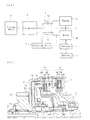
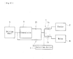
- the power transmitting apparatus of a first embodiment of the present invention is intended to transmit or cut off the driving force of an engine E and motor M of a hybrid vehicle to or from the wheels (driving wheels) D and mainly comprises, as shown in Figs. 1 and 2 , a first clutch means la, a second clutch means 1b, a third clutch means 2, and a selecting device 3.
- Fig.1 is a longitudinal-section view showing a main part of the power transmitting apparatus of a hybrid vehicle according to a first embodiment of the present invention
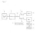
- Fig. 2 is a block diagram diagrammatic view showing the power transmitting apparatus of Fig. 1 .
- the power transmitting apparatus of the first embodiment of the present invention comprises a first clutch means 1a arranged on the way of a power transmitting system from the engine E mounted on a hybrid vehicle to driving wheels D and adapted to transmit or cut-off the driving force of the engine E to or from the driving wheels (D), a second clutch means 1b arranged on the way of a power transmitting system from a motor M mounted on a vehicle to the driving wheels D and adapted to transmit or cut-off the driving force of the motor M to or from the driving wheels D, and a transmission A.
- the first and second clutch means 1a, 1b are united and form a clutch means 1.
- FIG. 1 reference numerals 9, 11 and 12 denote input members rotated by the engine E and a damper mechanism 10 comprising coil springs is interposed between the input members 11 and 12.
- the input members 9, 11 are rotated by the driving force of the engine E and the driving force of engine E is transmitted to the input member 12 via the damper mechanism 10 to rotate a driving shaft 8 spline-engaged with the input member 12.
- the driving shaft 8 is connected to a rotational member 7 adapted to be rotated by the driving shaft 8.
- the motor M is connected to an inverter 4 and a battery 5 and adapted to be rotated by electric power supplied by the battery 5 as well as to be rotated by the engine E to generate electricity for charging the battery 5.
- the motor M comprises a stator 14 supported by a supporting member 13 and a rotor 15 supported by a rotational member 6 adapted to be rotated around the driving shaft 8 together with the rotor 15 by electric power supplied by the battery 5.
- the first clutch means 1a comprises a plurality of driving side clutch discs 1aa mounted on the rotational member 7 rotated by the engine E and a plurality of driven side clutch discs 1ab mounted on a boxy member 17. These driving side clutch discs 1aa and driven side clutch discs 1ab are alternately arranged each other to form a laminated structure and can be press-contacted and separated each other.
- Fig. 6 shows a condition in which the first clutch means 1a is activated and the driving side clutch discs 1aa and the driven side clutch discs 1ab are press-contacted each other.
- a plurality of driving side clutch discs 1ba are mounted on the rotational member 6 rotating together with the motor M and a plurality of driven side clutch discs 1bb are mounted on the boxy member 17.
- These driving side clutch discs 1ba and the driven side clutch discs 1bb are alternately arranged each other to form a laminated structure and can be press-contacted and separated each other.
- Fig. 7 shows a condition in which the second clutch means 1b is activated and the driving side clutch discs 1ba and the driven side clutch discs 1bb are press-contacted each other.
- the term "separated" used herein means a condition released from a pressure applied to the clutch discs and thus it is not limited only to a physically separated condition. The transmission of driving force is allowed under the press-ccntacted condition and cut off under the separated condition.
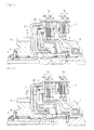
- the clutch means 1 comprises the first clutch means 1a, the second clutch means 1b and two hydraulic pistons P1 and P2 corresponding respectively to the first and second clutch means 1a, 1b contained in a same boxy member 17.
- the first and second clutch means 1a, 1b can be selectively activated by controlling the hydraulic pressure for actuating the hydraulic pistons P1, P2.
- the hydraulic piston P2 is moved toward the right in Fig. 3 against an urging force of a return spring 1c by supplying the operating oil into a hydraulic chamber S2 between the boxy member 17 and the hydraulic piston P2 and thus the second clutch means 1b is pressed by tips formed on the hydraulic piston P2 to press-contact the driving side clutch discs 1ba and the driven side clutch discs 1bb each other.
- the tips formed on the hydraulic piston P2 can be passed through recesses formed on the peripheries of the driving side clutch discs 1aa and the driven side clutch discs 1ab cf the first clutch means 1a as shown in Fig. 4 .
- the hydraulic piston P1 is moved toward the right in Fig. 3 against an urging force of a return spring 1c by supplying the operating oil into a hydraulic chamber S1 between the hydraulic piston P1 and the hydraulic piston P2 and thus the first clutch means 1a is pressed by tips formed on the hydraulic piston P1 to press-contact the driving side and driven side clutch discs 1aa, 1ab each other.
- the first clutch means 1a and the second clutch means 1b can be selectively activated by controlling the hydraulic pressures operating the hydraulic pistons P1 and P2 respectively.
- the boxy member 17 forming part of the clutch means 1 is connected to an interlocking member 18 formed thereon with a gear G1 mating with a gear formed on an output shaft (not shown).
- the driving force of the engine E or motor M transmitted through the first or second clutch means 1a or 1b can be transmitted to the interlocking member 18 through the boxy member 17 and further transmitted to the transmission A via the output shaft.
- the selecting device 3 selectively activates the first clutch means 1a or the second clutch means 1b by properly selected operation of the hydraulic pistons P1, P2 with supplying operating oil at a predetermined pressure into the hydraulic chamber S1 or S2 in accordance with running conditions of a vehicle in order to achieve any one of runs such as a run using the engine E as a driving power source, a run using the motor M as a driving power source, or a run using both the motor M and engine E as a driving power source.
- Such a selecting device 3 is for example formed in an ECU (Electronic Control Unit) for controlling the engine E or motor M.
- ECU Electronic Control Unit
- the power transmitting apparatus of a hybrid vehicle of the first embodiment of the present invention is so constructed that it can cut-off the power transmission from the engine E and motor M to the driving wheels D as well as transmit the driving force from one of the engine E and motor M to the other of them by connecting them each other. More particularly the power transmitting apparatus of the first embodiment is equipped with the third clutch means 2 which is arranged between the engine E and the motor M with bypassing the first and second clutch means 1a, 1b (i.e. so as to be able to directly connect the engine E and the motor M) and able to transmit the driving force from one of the engine E and motor M to the other of them.
- the third clutch means 2 is arranged at a radially inner side (inside) of the rotor 15 of the motor M and comprises driving side clutch discs 2a mounted on the rotational member 6 rotatable together with the motor M and driven side clutch discs 2b mounted on the connecting member 16 connected to the driving shaft 8.
- These driving side clutch discs 2a and driven side clutch discs 2b are alternately arranged each other to form a laminated structure and can be press-contacted and separated each other.
- Fig. 8 shows a condition in which the third clutch means 2 is activated and the driving side clutch discs 2a and the driven side clutch discs 2b are press-contacted each other.
- the third clutch means 2 has a hydraulic piston P3 and can be activated by controlling the hydraulic pressure for actuating the hydraulic piston P3. That is, the hydraulic piston P3 is moved toward the right in Fig. 5 against an urging force of a return spring 2c by supplying the operating oil into a hydraulic chamber S3 between the rotational member 6 and the hydraulic piston P3 and thus the third clutch means 2 is pressed by tips formed on the hydraulic piston P3 to press-contact the driving side clutch discs 2a and the driven side clutch discs 2b each other.
- the third clutch means 2 can be properly and selectively activated by the selecting device 3.
- Table of Fig. 9 shows contents of control of the first, second and third clutch means 1a, 1b and 2 performed by the selecting device 3. According to item (1) in Table of Fig. 9 , it is shown that start of the engine E in N (neutral) range of the transmission A can be achieved by the driving force from the motor M to the engine E without using any starter by not activating both the first and second clutch means 1a, 1b and activating the third clutch means 2.
- the power transmitting apparatus of a hybrid vehicle of the present invention is equipped with means for detecting remained electric amount of battery (not shown) (sometimes simply referred to as "remained electric amount detecting means").
- remained electric amount detecting means means for detecting remained electric amount of battery (not shown)
- the motor M generate electricity by cutting-off the driving force of the engine E to the driving wheels D and simultaneously transmitting the driving force of the engine E to the motor M with not activating both the first and second clutch means 1a, 1b and simultaneously activating the third clutch means 2.
- both the driving forces of the engine E and the motor M are simultaneously transmitted to the driving wheels D by activating both the first and second clutch means 1a, 1b with activating both the first and second clutch means 1a, 1b and not activating the third clutch means 2 so long as the remained electric amount of battery 5 detected by the remained electric amount detecting means is within an optimum range.
- the motor M generate electricity by recovering a power from the driving wheels D by cutting-off the driving power of the engine E to the driving wheels D with not activating both the first and third clutch means 1a, 2 and activating the second clutch means 1b during regenerative braking in D range of the transmission A.
- the reverse starting-up and reverse run can be performed by the motor M by reversely rotating the motor M and not activating both the first and third clutch means 1a, 2 and activating the second clutch means 1b.
- the power transmitting apparatus since the power transmitting apparatus is constructed so that it cuts-off the power transmission from the engine E and the motor M to the driving wheels D and connects the engine E and the motor M each other so as to transmit the power of one of them to the other, it is possible to keep stoppage of a vehicle with avoiding the transmission of driving force of them to the driving wheels D when trying to transmit the driving force of engine E to the motor M or reversely the driving force of motor M to the engine E during stoppage of a vehicle. Accordingly it is possible to start a stopped engine E without requiring any starter as well as to increase chances of charging a battery 5 with enabling a motor M generate electricity during stoppage of a vehicle.
- first clutch means 1a, the second clutch means 1b and two hydraulic pistons P1, P2 corresponding to the first and second clutch means 1a, 1b are arranged within a same boxy member 17, and the first and second clutch means 1a, 1b can be operated in a properly selective manner by controlling the hydraulic pressure for actuating the hydraulic pistons P1, P2, it is possible to further simplify the structure and reduce the size and weight of whole the power transmitting apparatus.
- the second clutch means 1b is activated to transmit the driving force of the motor m to the driving wheels D and simultaneously the first clutch 1a is deactivated to cut-off the driving force of the engine E to the driving wheels D on start-up and run of a vehicle driven by the motor M, it is possible to improve the efficiency of run performed by the motor M (see item (3) in Table of Fig. 9 ).
- the motor M is reversed on reverse start-up and reverse run of a vehicle driven by the motor M, it is possible to eliminate reverse gears etc. of a transmission and thus to simplify the structure and reduce the size of the power transmitting apparatus (see item (9) in Table of Fig. 9 ).
- both the driving forces of the engine E and the motor M are simultaneously transmitted to the driving wheels D with activating both the first and second clutch means 1a, 1b so long as the remained electric amount of battery detected by the remained electric amount detecting means is within an optimum range, it is possible to reduce the driving force of the engine E and thus improve the fuel consumption (see item (5) in Table of Fig. 9 ).
- the driving force of the engine E is transmitted both to the driving wheels D and the motor M to make the motor M generate electricity when the remained electric amount of battery 5 detected by the remained electric amount detecting means during run of a vehicle is less than the predetermined value, it is possible to make the motor M generate electricity to charge the battery 5 during run of a vehicle (see item (6) in Table of Fig. 9 ).
- an automatic transmission A is arranged on the way of a power transmitting system between the first and second clutch means 1a, 1b and the driving wheels D and the speed of a vehicle can be changed by the automatic transmission A, it is possible to change the running speed of a vehicle by the automatic transmission A in accordance with the running state of a vehicle and thus adjust the driving force or engine revolution.
- the automatic transmission may be a double clutch type transmission or a single clutch type transmission.
- the third clutch means 2 is arranged at a radially inner side of a rotor 15 of the motor M, it is possible to add the third clutch means 2 without increasing the axial dimension of the power transmitting apparatus. Furthermore, since a damper mechanism for damping a torque variation is arranged on the way of a power transmitting system between the engine E and the first clutch means 1a, it is possible to transmit the driving force of the engine E to the first clutch means 1a with suppressing torque variation.
- the variable speed unit A of the present invention is preferably an continuously variable speed transmission 22 (e.g. CVT: Continuously Variable Transmission) as shown in Fig. 10 .
- the continuously variable speed transmission 22 may be arranged between the clutch means 1 and the driving wheels D on the way of a power transmitting system from the driving source (engine E and motor M) of a vehicle to the driving wheels D.
- Such an continuously variable speed transmission 22 comprises two pulleys Q1, Q2 and a belt V extending therebetween and can achieve a desired speed by independently changing diameters of the pulleys Q1, Q2 on which the belt V runs by a hydraulic pressure control circuit 20.
- a character "F" in Fig. 10 denotes a differential gear equipped with a vehicle.
- the continuously variable speed transmission 22 further comprises a CVT ECU 19 electrically connected to a brake switch of a brake pedal, a position sensor of a shifting lever, an engine ECU (not shown) etc. and the hydraulic control circuit 20 is further controlled by the CVT ECU 19.
- the hydraulic pistons P1-P3 previously described are also controlled by the hydraulic pressure control circuit 20.
- an electrically driven oil pump 21 which can properly activate the first clutch means 1a, second clutch means 1b or third clutch means 2 by a hydraulic pressure generated by itself. This makes it possible to activate the first and second clutch means 1a, 1b and third clutch means 2 even if the mechanical pump mounted on a vehicle cannot be operated e.g. on motor starting-up during stoppage of a vehicle.
- the power transmitting apparatus of a hybrid vehicle of a second embodiment of the present invention is intended to transmit or cut-off the driving force of the engine E and the motor M as the power source of a hybrid vehicle to the driving wheels D and has a fourth clutch means 23 which is arranged, as shown in Fig. 11 , between the output side of the first and second clutch means 1a, 1b and the transmission A mounted on a vehicle and adapted to transmit or cut-off the driving force of the engine E or the motor M to the transmission A.
- Same reference numerals are used herein for designating same structural elements as those used in the first embodiment and detailed description of them will be omitted.
- This embodiment is constructed so that it cuts-off the power transmission from the engine E and the motor M to the driving wheels D and connects the engine E and the motor M so as to transmit the power from one of them to the other. That is, the fourth clutch means 23 enables to cut-off the power transmission from the engine E and the motor M to the driving wheels D as well as the first and second clutch means 1a, 1b enable to connect the engine E and the motor M so as to transmit the power from one of them to the other.
- the fourth clutch means 23 can be properly and selectively activated by the selecting device 3.
- Table of Fig. 12 shows contents of control of the first, second clutch means 1a, 1b and the fourth clutch means 23 performed by the selecting device 3.
- Fig. 13 shows a modification in which the transmission A is replaced with the continuously variable speed transmission (CVT) 22.
- CVT continuously variable speed transmission
- this embodiment is constructed so that it cuts-off the power transmission from the engine E and the motor M to the driving wheels D and connects the engine E and the motor M so as to transmit the power from one of them to the other, it is possible to keep stoppage of a vehicle with avoiding the transmission of driving force of them to the driving wheels D when trying to transmit the driving force of engine E to the motor M or reversely the driving force of motor M to the engine E during stoppage of a vehicle. Accordingly, it is possible to start a stopped engine E without requiring any starter as well as to increase chances of charging a battery 5 with enabling a motor M generate electricity during stoppage of a vehicle.
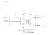
- the power transmitting apparatus of a hybrid vehicle of a third embodiment of the present invention is intended to transmit or cut-off the driving force of Lhe engine E and the motor M as the power source of a hybrid vehicle to the driving wheels D and has a fourth clutch means 24 which is arranged between the output side of the first and second clutch means 1a, 1b and the transmission A mounted on a vehicle and adapted to transmit or cut-off the driving force of the engine E or the motor M to the transmission A.
- the fourth clutch means 24 comprises a fourth clutch means for odd numbered gear 24a and a fourth clutch means for even numbered gear 24b. Same reference numerals are used herein for designating same structural elements as those used in the first and second embodiments and detailed description of them will be omitted.
- This embodiment is constructed so that it cuts-off the power transmission from the engine E and the motor M to the driving wheels D and connects the engine E and the motor M so as to transmit the power from one of them to the other. That is, the fourth clutch means 24 (fourth clutch means for odd numbered gear 24a and fourth clutch means for even numbered gear 24b) enables to cut-off the power transmissicn from the engine E and the motor M to the driving wheels D as well as the first and second clutch means 1a, 1b enables to connect the engine E and the motor M so as to transmit the power from one of them to the other.
- the fourth clutch means 24 (fourth clutch means for odd numbered gear 24a and fourth clutch means for even numbered gear 24b) can be properly and selectively activated by the selecting device 3.
- Table of Fig. 15 shows contents of control of the first, second clutch means 1a, 1b and fourth clutch means 24 performed by the selecting device 3.
- Fig. 16 shows a modification in which the transmission A is replaced with a DCT (Dual Clutch Transmission) 25 equipped with transmissions for odd and even numbered gears.
- a reference numeral 19' denotes DCT ECU.
- this embodiment is constructed so that it cuts-off the power transmission from the engine E and the motor M to the driving wheels D and connects the engine E and the motor M so as tc transmit the power from one of them to the other, it is possible to keep stoppage of a vehicle with avoiding the transmission of driving force of them to the driving wheels D when trying to transmit the driving force of engine E to the motor M or reversely the driving force of motor M to the engine E during stoppage of a vehicle. Accordingly, it is possible to start a stopped engine E without requiring any starter as well as to increase chances of charging a battery 5 with enabling a motor M generate electricity during stoppage of a vehicle.
- the power transmitting apparatus of a hybrid vehicle of a fourth embodiment of the present invention will be described.
- the power transmitting apparatus of this embodiment is intended to transmit or cut-off the driving force of the engine E and the motor M as the power source of a hybrid vehicle to the driving wheels D.
- a fifth clutch means 26 in addition to the fourth clutch means 23 (see the second embodiment) arranged between the output side of the first and second clutch means 1a, 1b and the transmission A mounted on a vehicle and adapted to transmit or cut-off the driving force of the engine E or the motor M to or from the transmission A.
- the fifth clutch means 26 is arranged between the output side of the first and second clutch means 1a, 1b and the driving wheels D with bypassing the transmission A and adapted to transmit and cut-off the driving force of the engine E or motor M to or from the driving wheels D without via the transmission A.
- Same reference numerals are used herein for designating same structural elements as those used in the first-third embodiments and detailed description of them will be omitted.
- This embodiment is constructed so that it cuts-off the power transmission from the engine E and the motor M to the driving wheels D and connects the engine E and the motor M so as to transmit the power from one of them to the other. That is, the fourth clutch means 23 and fifth clutch means 26 enable to cut-off the power transmission from the engine E and the motor M to the driving wheels D as well as the first and second clutch means 1a, 1b enable to connect the engine E and the motor M so as to transmit the power from one of them to the other.
- Fig. 18 shows a modification in which the transmission A is replaced with a three-speed AMT 27 (Automatic Manual transmission).
- a reference numeral 19" denotes AMT ECU.
- this embodiment is constructed so that it cuts-off the power transmission from the engine E and the motor M to the driving wheels D and connects the engine E and the motor M so as to transmit the power from one of them to the other, it is possible to keep stoppage of a vehicle with avoiding the transmission of driving force of them to the driving wheels D when trying to transmit the driving force of engine E to the motor M or reversely the driving force of motor M to the engine E during stoppage of a vehicle. Accordingly it is possible to start a stopped engine E without requiring any starter as well as to increase chances of charging a battery 5 with enabling a motor M generate electricity during stoppage of a vehicle.
- the present invention is not limited to that described and shown herein.
- the power transmitting apparatus of the present invention may be constructed using other types of clutches in place of the third - fifth clutch means if they can connects the engine E and the motor M and transmit the power from one of them to the other.
- the present invention can be applied to any type of hybrid vehicle equipped with internal combustion engines including not only a gasoline engine but also a diesel engine.
- the selecting device 3 is formed in the ECU, it may be formed in a separately arranged microcomputer.
- the present invention can be applied to any power transmitting apparatus having different configurations in its external appearance or structural parts or those having additional functions if the power transmitting apparatus is a power transmitting apparatus of a hybrid vehicle which can cut-off the power transmission from an engine and a motor to driving wheels and connect the engine and the motor so as to transmit the power from one of them to the other. Description of Reference numerals
Landscapes
- Engineering & Computer Science (AREA)
- Transportation (AREA)
- Mechanical Engineering (AREA)
- Chemical & Material Sciences (AREA)
- Combustion & Propulsion (AREA)
- Automation & Control Theory (AREA)
- Power Engineering (AREA)
- Hybrid Electric Vehicles (AREA)
- Electric Propulsion And Braking For Vehicles (AREA)
- Arrangement Of Transmissions (AREA)
Applications Claiming Priority (2)
| Application Number | Priority Date | Filing Date | Title |
|---|---|---|---|
| JP2008288696A JP5207925B2 (ja) | 2008-11-11 | 2008-11-11 | ハイブリッド車両の動力伝達装置 |
| PCT/JP2009/005972 WO2010055637A1 (fr) | 2008-11-11 | 2009-11-10 | Dispositif de transmission de puissance pour véhicule hybride |
Publications (3)
| Publication Number | Publication Date |
|---|---|
| EP2383140A1 true EP2383140A1 (fr) | 2011-11-02 |
| EP2383140A4 EP2383140A4 (fr) | 2014-01-08 |
| EP2383140B1 EP2383140B1 (fr) | 2017-05-24 |
Family
ID=42169783
Family Applications (1)
| Application Number | Title | Priority Date | Filing Date |
|---|---|---|---|
| EP09825891.6A Not-in-force EP2383140B1 (fr) | 2008-11-11 | 2009-11-10 | Dispositif de transmission de puissance pour véhicule hybride |
Country Status (5)
| Country | Link |
|---|---|
| US (1) | US9302576B2 (fr) |
| EP (1) | EP2383140B1 (fr) |
| JP (1) | JP5207925B2 (fr) |
| CN (1) | CN102271948A (fr) |
| WO (1) | WO2010055637A1 (fr) |
Cited By (2)
| Publication number | Priority date | Publication date | Assignee | Title |
|---|---|---|---|---|
| WO2017178002A1 (fr) * | 2016-04-14 | 2017-10-19 | Schaeffler Technologies AG & Co. KG | Chaîne cinématique pour véhicule automobile hybride |
| FR3069296A1 (fr) * | 2017-07-21 | 2019-01-25 | Valeo Embrayages | Dispositif de transmission pour vehicule hybride |
Families Citing this family (30)
| Publication number | Priority date | Publication date | Assignee | Title |
|---|---|---|---|---|
| DE102007027898A1 (de) * | 2007-06-18 | 2008-12-24 | Robert Bosch Gmbh | Elektrowerkzeug mit Kaltstartfunktion |
| DE102009059944A1 (de) * | 2009-01-19 | 2010-07-22 | Luk Lamellen Und Kupplungsbau Beteiligungs Kg | Hybridmodul für einen Antriebsstrang eines Fahrzeuges |
| JP5310783B2 (ja) * | 2011-05-16 | 2013-10-09 | 株式会社デンソー | 動力伝達装置 |
| JP5807379B2 (ja) * | 2011-05-16 | 2015-11-10 | 日産自動車株式会社 | ハイブリッド車両のエンジン停止制御装置 |
| JP2013095260A (ja) * | 2011-10-31 | 2013-05-20 | Aisin Aw Co Ltd | ハイブリッド駆動装置 |
| JP5793063B2 (ja) * | 2011-11-14 | 2015-10-14 | Gknドライブラインジャパン株式会社 | 動力伝達装置 |
| US8989978B2 (en) * | 2012-03-06 | 2015-03-24 | Ford Global Technologies, Llc | Method for operating a vehicle powertrain |
| JP2013203235A (ja) * | 2012-03-28 | 2013-10-07 | Kubota Corp | ハイブリッド作業車 |
| JP5626601B2 (ja) * | 2012-05-31 | 2014-11-19 | 株式会社デンソー | 車両駆動システムの制御装置 |
| CN103078444A (zh) * | 2013-01-14 | 2013-05-01 | 淄博得普达电机有限公司 | 电动机发电系统 |
| US9989150B2 (en) * | 2013-03-22 | 2018-06-05 | Jatco Ltd | Control device for belt-type continuously variable transmission |
| JP5942941B2 (ja) * | 2013-07-30 | 2016-06-29 | トヨタ自動車株式会社 | ハイブリッドシステム |
| US9834098B2 (en) * | 2014-01-30 | 2017-12-05 | General Electric Company | Vehicle propulsion system with multi-channel DC bus and method of manufacturing same |
| US9227630B2 (en) * | 2014-02-17 | 2016-01-05 | Ford Global Technologies, Llc | Smoothing hybrid vehicle engine shutdown |
| JP6237878B2 (ja) * | 2014-02-28 | 2017-11-29 | アイシン・エィ・ダブリュ株式会社 | 車両用駆動装置の制御装置 |
| JP6438201B2 (ja) * | 2014-03-13 | 2018-12-12 | ジヤトコ株式会社 | 無段変速機付きハイブリッド車両 |
| JP6343506B2 (ja) * | 2014-07-08 | 2018-06-13 | ジヤトコ株式会社 | 駆動機構 |
| JP6270653B2 (ja) * | 2014-07-25 | 2018-01-31 | トヨタ自動車株式会社 | 車両用駆動装置 |
| KR101655580B1 (ko) | 2014-11-26 | 2016-09-07 | 현대자동차주식회사 | 하이브리드 차량용 구동장치 |
| JP6420653B2 (ja) * | 2014-12-11 | 2018-11-07 | 株式会社エフ・シー・シー | ハイブリッド車両の動力伝達装置 |
| JP6470621B2 (ja) * | 2015-04-03 | 2019-02-13 | 株式会社エフ・シー・シー | ハイブリッド車両の動力伝達装置 |
| CN105346540B (zh) * | 2015-12-03 | 2017-10-27 | 湖南大学 | 一种车用混合动力总成及其控制方法 |
| US10259448B2 (en) * | 2016-08-17 | 2019-04-16 | GM Global Technology Operations LLC | Hybrid vehicle propulsion systems and methods |
| CN109715967B (zh) | 2016-09-20 | 2021-10-01 | 舍弗勒技术股份两合公司 | 多重离合装置和用于机动车的混合动力模块 |
| DE102017209666A1 (de) * | 2017-06-08 | 2018-12-13 | Robert Bosch Gmbh | Verfahren und Vorrichtung zum Bereitstellen eines Signals zum Betreiben von wenigstens zwei Fahrzeugen |
| CN108116217B (zh) | 2017-12-20 | 2019-10-15 | 广州汽车集团股份有限公司 | 双行星排的混合动力耦合机构及机动车辆 |
| JP7256612B2 (ja) * | 2018-07-12 | 2023-04-12 | 株式会社日立ニコトランスミッション | 鉄道作業車用トランスミッション |
| JP6601986B2 (ja) * | 2018-10-12 | 2019-11-06 | 株式会社エフ・シー・シー | ハイブリッド車両の動力伝達装置 |
| CN111059243B (zh) * | 2019-12-18 | 2023-10-27 | 浙江吉利汽车研究院有限公司 | 一种混合动力变速器及车辆 |
| NL2026153B1 (en) * | 2020-07-28 | 2022-03-29 | Punch Powertrain Psa E Trans N V | Dual clutch transmission system |
Family Cites Families (21)
| Publication number | Priority date | Publication date | Assignee | Title |
|---|---|---|---|---|
| JPH02146345A (ja) | 1988-11-28 | 1990-06-05 | Aisin Aw Co Ltd | 自動変速機のクラツチの配設構造 |
| JP3635460B2 (ja) * | 2000-12-28 | 2005-04-06 | 株式会社日立製作所 | 動力伝達装置 |
| JP3502058B2 (ja) * | 2001-04-16 | 2004-03-02 | 富士重工業株式会社 | 自動変速機 |
| FR2833538B1 (fr) * | 2001-12-18 | 2004-02-20 | Renault | Dispositif de transmission de puissance et groupe motopropulseur hybride associe |
| JP3922187B2 (ja) * | 2003-02-14 | 2007-05-30 | 日産自動車株式会社 | 自動クラッチ式歯車変速機の変速制御装置 |
| JP2004306826A (ja) | 2003-04-08 | 2004-11-04 | Fuji Heavy Ind Ltd | ハイブリッド車両の駆動装置 |
| JP4039355B2 (ja) | 2003-10-29 | 2008-01-30 | トヨタ自動車株式会社 | 二次電池の制御装置および制御方法 |
| JP2006029476A (ja) * | 2004-07-16 | 2006-02-02 | Nissan Motor Co Ltd | 駆動力伝達装置 |
| JP2006199081A (ja) * | 2005-01-19 | 2006-08-03 | Hitachi Ltd | 自動車用動力伝達装置 |
| EP1882110B1 (fr) | 2005-05-17 | 2012-05-30 | BorgWarner, Inc. | Mecanisme de double embrayage pour boite de vitesses |
| US7272986B2 (en) * | 2005-07-15 | 2007-09-25 | Ford Global Technologies, Llc | Dual input automatic transaxle |
| DE102005039461A1 (de) * | 2005-08-20 | 2007-03-15 | Daimlerchrysler Ag | Hybrider Antriebsstrang eines Kraftfahrzeugs und Verfahren zum Betrieb eines hybriden Antriebsstrangs |
| US7256510B2 (en) | 2005-12-23 | 2007-08-14 | General Motors Corportion | Hybrid electro-mechanical transmission with single motor/generator and method of control |
| JP4821578B2 (ja) * | 2006-02-28 | 2011-11-24 | 日産自動車株式会社 | 自動変速機 |
| JP3121527U (ja) | 2006-02-28 | 2006-05-18 | 株式会社ダイナックス | 湿式クラッチ構造 |
| CN2936821Y (zh) | 2006-08-29 | 2007-08-22 | 比亚迪股份有限公司 | 一种混合动力驱动系统 |
| JP2008143242A (ja) * | 2006-12-06 | 2008-06-26 | Mazda Motor Corp | 車両用駆動装置 |
| CN201003577Y (zh) | 2006-12-27 | 2008-01-09 | 上海汽车股份有限公司 | 混合动力汽车的驱动系统 |
| CN101088820A (zh) | 2007-07-20 | 2007-12-19 | 北京工业大学 | 串联式混合动力电动汽车辅助动力单元控制方法 |
| JP4189695B1 (ja) * | 2007-09-28 | 2008-12-03 | 三菱自動車工業株式会社 | 車両の制御装置 |
| US8052578B2 (en) * | 2008-05-30 | 2011-11-08 | Honda Motor Co., Ltd. | Hydraulic vehicle clutch system and preemptive control method |
-
2008
- 2008-11-11 JP JP2008288696A patent/JP5207925B2/ja not_active Expired - Fee Related
-
2009
- 2009-11-10 CN CN200980154157.7A patent/CN102271948A/zh active Pending
- 2009-11-10 WO PCT/JP2009/005972 patent/WO2010055637A1/fr not_active Ceased
- 2009-11-10 EP EP09825891.6A patent/EP2383140B1/fr not_active Not-in-force
-
2011
- 2011-05-10 US US13/104,868 patent/US9302576B2/en active Active
Cited By (3)
| Publication number | Priority date | Publication date | Assignee | Title |
|---|---|---|---|---|
| WO2017178002A1 (fr) * | 2016-04-14 | 2017-10-19 | Schaeffler Technologies AG & Co. KG | Chaîne cinématique pour véhicule automobile hybride |
| US10843547B2 (en) | 2016-04-14 | 2020-11-24 | Schaeffler Technologies AG & Co. KG | Drive train for a hybrid motor vehicle |
| FR3069296A1 (fr) * | 2017-07-21 | 2019-01-25 | Valeo Embrayages | Dispositif de transmission pour vehicule hybride |
Also Published As
| Publication number | Publication date |
|---|---|
| US20110301796A1 (en) | 2011-12-08 |
| CN102271948A (zh) | 2011-12-07 |
| EP2383140B1 (fr) | 2017-05-24 |
| US9302576B2 (en) | 2016-04-05 |
| JP2010115943A (ja) | 2010-05-27 |
| EP2383140A4 (fr) | 2014-01-08 |
| WO2010055637A1 (fr) | 2010-05-20 |
| JP5207925B2 (ja) | 2013-06-12 |
Similar Documents
| Publication | Publication Date | Title |
|---|---|---|
| EP2383140B1 (fr) | Dispositif de transmission de puissance pour véhicule hybride | |
| RU2628618C2 (ru) | Гибридный привод, транспортное средство с таким гибридным приводом, способ управления таким гибридным приводом | |
| US7240751B2 (en) | Dual rotor motor for a hybrid vehicle transmission | |
| CN105383278B (zh) | 具有发动机起动和再生制动模式的动力总成 | |
| KR101978894B1 (ko) | 하이브리드 파워트레인, 이러한 하이브리드 파워트레인을 제어하는 방법, 이러한 하이브리드 파워트레인을 포함하는 차량, 이러한 하이브리드 파워트레인을 제어하는 컴퓨터 프로그램 및 프로그램 코드를 포함하는 컴퓨터 프로그램 제품 | |
| US8661941B2 (en) | Hybrid drive system | |
| JP3682964B2 (ja) | 車両用駆動装置 | |
| CN102328578B (zh) | 用于机动车辆的驱动系统及具有这种驱动系统的机动车辆 | |
| US20030217617A1 (en) | Transmission | |
| WO2011138892A1 (fr) | Système de propulsion de véhicule hybride | |
| US9605605B2 (en) | Vehicle control apparatus | |
| US20140342873A1 (en) | Vehicle control apparatus | |
| JP2002542752A (ja) | 自動車用の切換え可能なクラッチを有するハイブリッド駆動システム | |
| JP2016501153A (ja) | ハイブリッド車両における内燃機関の始動方法 | |
| CN101918237A (zh) | 车辆用驱动装置 | |
| CN105307887A (zh) | 用于混合式传动系变速箱以及控制所述变速箱的方法 | |
| WO2014199457A1 (fr) | Dispositif et procédé de commande de véhicule | |
| CN111976462A (zh) | 混合动力车辆的驱动装置 | |
| JP5115465B2 (ja) | 駆動装置 | |
| JP2016112943A (ja) | ハイブリッド車両の動力伝達装置 | |
| KR101794898B1 (ko) | 차량용 추진 시스템 | |
| US7762921B2 (en) | Powertrain and method of controlling powertrain | |
| KR101828987B1 (ko) | 하이브리드 드라이브 라인의 연소 엔진 시동 방법 | |
| CN111601989A (zh) | 用于机动车的动力传动系和用于在这种动力传动系中启动内燃机的方法 |
Legal Events
| Date | Code | Title | Description |
|---|---|---|---|
| PUAI | Public reference made under article 153(3) epc to a published international application that has entered the european phase |
Free format text: ORIGINAL CODE: 0009012 |
|
| 17P | Request for examination filed |
Effective date: 20110614 |
|
| AK | Designated contracting states |
Kind code of ref document: A1 Designated state(s): AT BE BG CH CY CZ DE DK EE ES FI FR GB GR HR HU IE IS IT LI LT LU LV MC MK MT NL NO PL PT RO SE SI SK SM TR |
|
| DAX | Request for extension of the european patent (deleted) | ||
| A4 | Supplementary search report drawn up and despatched |
Effective date: 20131205 |
|
| RIC1 | Information provided on ipc code assigned before grant |
Ipc: B60W 10/06 20060101ALI20131129BHEP Ipc: B60W 20/00 20060101ALI20131129BHEP Ipc: B60K 6/387 20071001AFI20131129BHEP Ipc: B60K 6/543 20071001ALI20131129BHEP Ipc: F16H 9/18 20060101ALI20131129BHEP Ipc: B60W 10/02 20060101ALI20131129BHEP Ipc: F16H 3/00 20060101ALI20131129BHEP Ipc: B60W 10/08 20060101ALI20131129BHEP Ipc: B60W 10/113 20120101ALI20131129BHEP Ipc: B60K 6/547 20071001ALI20131129BHEP Ipc: B60L 11/14 20060101ALI20131129BHEP Ipc: B60K 6/40 20071001ALI20131129BHEP Ipc: B60K 17/02 20060101ALI20131129BHEP Ipc: B60K 6/48 20071001ALI20131129BHEP |
|
| GRAP | Despatch of communication of intention to grant a patent |
Free format text: ORIGINAL CODE: EPIDOSNIGR1 |
|
| RIC1 | Information provided on ipc code assigned before grant |
Ipc: B60W 10/113 20120101ALI20161102BHEP Ipc: F16H 3/00 20060101ALI20161102BHEP Ipc: B60K 6/543 20071001ALI20161102BHEP Ipc: B60K 17/02 20060101ALI20161102BHEP Ipc: B60K 6/48 20071001ALI20161102BHEP Ipc: F16H 9/18 20060101ALI20161102BHEP Ipc: B60W 10/02 20060101ALI20161102BHEP Ipc: B60K 6/547 20071001ALI20161102BHEP Ipc: B60W 20/00 20160101ALI20161102BHEP Ipc: B60W 10/08 20060101ALI20161102BHEP Ipc: B60K 6/387 20071001AFI20161102BHEP Ipc: B60W 10/06 20060101ALI20161102BHEP Ipc: B60K 6/40 20071001ALI20161102BHEP Ipc: B60L 11/14 20060101ALI20161102BHEP |
|
| INTG | Intention to grant announced |
Effective date: 20161208 |
|
| GRAS | Grant fee paid |
Free format text: ORIGINAL CODE: EPIDOSNIGR3 |
|
| GRAA | (expected) grant |
Free format text: ORIGINAL CODE: 0009210 |
|
| AK | Designated contracting states |
Kind code of ref document: B1 Designated state(s): AT BE BG CH CY CZ DE DK EE ES FI FR GB GR HR HU IE IS IT LI LT LU LV MC MK MT NL NO PL PT RO SE SI SK SM TR |
|
| REG | Reference to a national code |
Ref country code: GB Ref legal event code: FG4D |
|
| REG | Reference to a national code |
Ref country code: CH Ref legal event code: EP |
|
| REG | Reference to a national code |
Ref country code: IE Ref legal event code: FG4D |
|
| REG | Reference to a national code |
Ref country code: AT Ref legal event code: REF Ref document number: 895842 Country of ref document: AT Kind code of ref document: T Effective date: 20170615 |
|
| REG | Reference to a national code |
Ref country code: DE Ref legal event code: R096 Ref document number: 602009046287 Country of ref document: DE |
|
| REG | Reference to a national code |
Ref country code: NL Ref legal event code: MP Effective date: 20170524 |
|
| REG | Reference to a national code |
Ref country code: LT Ref legal event code: MG4D |
|
| REG | Reference to a national code |
Ref country code: AT Ref legal event code: MK05 Ref document number: 895842 Country of ref document: AT Kind code of ref document: T Effective date: 20170524 |
|
| PG25 | Lapsed in a contracting state [announced via postgrant information from national office to epo] |
Ref country code: HR Free format text: LAPSE BECAUSE OF FAILURE TO SUBMIT A TRANSLATION OF THE DESCRIPTION OR TO PAY THE FEE WITHIN THE PRESCRIBED TIME-LIMIT Effective date: 20170524 Ref country code: GR Free format text: LAPSE BECAUSE OF FAILURE TO SUBMIT A TRANSLATION OF THE DESCRIPTION OR TO PAY THE FEE WITHIN THE PRESCRIBED TIME-LIMIT Effective date: 20170825 Ref country code: ES Free format text: LAPSE BECAUSE OF FAILURE TO SUBMIT A TRANSLATION OF THE DESCRIPTION OR TO PAY THE FEE WITHIN THE PRESCRIBED TIME-LIMIT Effective date: 20170524 Ref country code: NO Free format text: LAPSE BECAUSE OF FAILURE TO SUBMIT A TRANSLATION OF THE DESCRIPTION OR TO PAY THE FEE WITHIN THE PRESCRIBED TIME-LIMIT Effective date: 20170824 Ref country code: FI Free format text: LAPSE BECAUSE OF FAILURE TO SUBMIT A TRANSLATION OF THE DESCRIPTION OR TO PAY THE FEE WITHIN THE PRESCRIBED TIME-LIMIT Effective date: 20170524 Ref country code: AT Free format text: LAPSE BECAUSE OF FAILURE TO SUBMIT A TRANSLATION OF THE DESCRIPTION OR TO PAY THE FEE WITHIN THE PRESCRIBED TIME-LIMIT Effective date: 20170524 Ref country code: LT Free format text: LAPSE BECAUSE OF FAILURE TO SUBMIT A TRANSLATION OF THE DESCRIPTION OR TO PAY THE FEE WITHIN THE PRESCRIBED TIME-LIMIT Effective date: 20170524 |
|
| PG25 | Lapsed in a contracting state [announced via postgrant information from national office to epo] |
Ref country code: NL Free format text: LAPSE BECAUSE OF FAILURE TO SUBMIT A TRANSLATION OF THE DESCRIPTION OR TO PAY THE FEE WITHIN THE PRESCRIBED TIME-LIMIT Effective date: 20170524 Ref country code: LV Free format text: LAPSE BECAUSE OF FAILURE TO SUBMIT A TRANSLATION OF THE DESCRIPTION OR TO PAY THE FEE WITHIN THE PRESCRIBED TIME-LIMIT Effective date: 20170524 Ref country code: IS Free format text: LAPSE BECAUSE OF FAILURE TO SUBMIT A TRANSLATION OF THE DESCRIPTION OR TO PAY THE FEE WITHIN THE PRESCRIBED TIME-LIMIT Effective date: 20170924 Ref country code: SE Free format text: LAPSE BECAUSE OF FAILURE TO SUBMIT A TRANSLATION OF THE DESCRIPTION OR TO PAY THE FEE WITHIN THE PRESCRIBED TIME-LIMIT Effective date: 20170524 Ref country code: BG Free format text: LAPSE BECAUSE OF FAILURE TO SUBMIT A TRANSLATION OF THE DESCRIPTION OR TO PAY THE FEE WITHIN THE PRESCRIBED TIME-LIMIT Effective date: 20170824 |
|
| PG25 | Lapsed in a contracting state [announced via postgrant information from national office to epo] |
Ref country code: RO Free format text: LAPSE BECAUSE OF FAILURE TO SUBMIT A TRANSLATION OF THE DESCRIPTION OR TO PAY THE FEE WITHIN THE PRESCRIBED TIME-LIMIT Effective date: 20170524 Ref country code: SK Free format text: LAPSE BECAUSE OF FAILURE TO SUBMIT A TRANSLATION OF THE DESCRIPTION OR TO PAY THE FEE WITHIN THE PRESCRIBED TIME-LIMIT Effective date: 20170524 Ref country code: DK Free format text: LAPSE BECAUSE OF FAILURE TO SUBMIT A TRANSLATION OF THE DESCRIPTION OR TO PAY THE FEE WITHIN THE PRESCRIBED TIME-LIMIT Effective date: 20170524 Ref country code: EE Free format text: LAPSE BECAUSE OF FAILURE TO SUBMIT A TRANSLATION OF THE DESCRIPTION OR TO PAY THE FEE WITHIN THE PRESCRIBED TIME-LIMIT Effective date: 20170524 Ref country code: CZ Free format text: LAPSE BECAUSE OF FAILURE TO SUBMIT A TRANSLATION OF THE DESCRIPTION OR TO PAY THE FEE WITHIN THE PRESCRIBED TIME-LIMIT Effective date: 20170524 |
|
| REG | Reference to a national code |
Ref country code: DE Ref legal event code: R097 Ref document number: 602009046287 Country of ref document: DE |
|
| PG25 | Lapsed in a contracting state [announced via postgrant information from national office to epo] |
Ref country code: PL Free format text: LAPSE BECAUSE OF FAILURE TO SUBMIT A TRANSLATION OF THE DESCRIPTION OR TO PAY THE FEE WITHIN THE PRESCRIBED TIME-LIMIT Effective date: 20170524 Ref country code: IT Free format text: LAPSE BECAUSE OF FAILURE TO SUBMIT A TRANSLATION OF THE DESCRIPTION OR TO PAY THE FEE WITHIN THE PRESCRIBED TIME-LIMIT Effective date: 20170524 Ref country code: SM Free format text: LAPSE BECAUSE OF FAILURE TO SUBMIT A TRANSLATION OF THE DESCRIPTION OR TO PAY THE FEE WITHIN THE PRESCRIBED TIME-LIMIT Effective date: 20170524 |
|
| PLBE | No opposition filed within time limit |
Free format text: ORIGINAL CODE: 0009261 |
|
| STAA | Information on the status of an ep patent application or granted ep patent |
Free format text: STATUS: NO OPPOSITION FILED WITHIN TIME LIMIT |
|
| 26N | No opposition filed |
Effective date: 20180227 |
|
| PG25 | Lapsed in a contracting state [announced via postgrant information from national office to epo] |
Ref country code: SI Free format text: LAPSE BECAUSE OF FAILURE TO SUBMIT A TRANSLATION OF THE DESCRIPTION OR TO PAY THE FEE WITHIN THE PRESCRIBED TIME-LIMIT Effective date: 20170524 |
|
| PG25 | Lapsed in a contracting state [announced via postgrant information from national office to epo] |
Ref country code: MC Free format text: LAPSE BECAUSE OF FAILURE TO SUBMIT A TRANSLATION OF THE DESCRIPTION OR TO PAY THE FEE WITHIN THE PRESCRIBED TIME-LIMIT Effective date: 20170524 |
|
| GBPC | Gb: european patent ceased through non-payment of renewal fee |
Effective date: 20171110 |
|
| PG25 | Lapsed in a contracting state [announced via postgrant information from national office to epo] |
Ref country code: CH Free format text: LAPSE BECAUSE OF NON-PAYMENT OF DUE FEES Effective date: 20171130 Ref country code: LI Free format text: LAPSE BECAUSE OF NON-PAYMENT OF DUE FEES Effective date: 20171130 |
|
| PG25 | Lapsed in a contracting state [announced via postgrant information from national office to epo] |
Ref country code: LU Free format text: LAPSE BECAUSE OF NON-PAYMENT OF DUE FEES Effective date: 20171110 |
|
| REG | Reference to a national code |
Ref country code: FR Ref legal event code: ST Effective date: 20180731 Ref country code: BE Ref legal event code: MM Effective date: 20171130 |
|
| REG | Reference to a national code |
Ref country code: IE Ref legal event code: MM4A |
|
| PG25 | Lapsed in a contracting state [announced via postgrant information from national office to epo] |
Ref country code: MT Free format text: LAPSE BECAUSE OF NON-PAYMENT OF DUE FEES Effective date: 20171110 |
|
| PG25 | Lapsed in a contracting state [announced via postgrant information from national office to epo] |
Ref country code: FR Free format text: LAPSE BECAUSE OF NON-PAYMENT OF DUE FEES Effective date: 20171130 Ref country code: IE Free format text: LAPSE BECAUSE OF NON-PAYMENT OF DUE FEES Effective date: 20171110 |
|
| PG25 | Lapsed in a contracting state [announced via postgrant information from national office to epo] |
Ref country code: BE Free format text: LAPSE BECAUSE OF NON-PAYMENT OF DUE FEES Effective date: 20171130 Ref country code: GB Free format text: LAPSE BECAUSE OF NON-PAYMENT OF DUE FEES Effective date: 20171110 |
|
| RIC2 | Information provided on ipc code assigned after grant |
Ipc: B60W 10/02 20060101ALI20161102BHEP Ipc: B60K 6/387 20071001AFI20161102BHEP Ipc: B60K 17/02 20060101ALI20161102BHEP Ipc: B60W 10/06 20060101ALI20161102BHEP Ipc: B60K 6/40 20071001ALI20161102BHEP Ipc: F16H 9/18 20060101ALI20161102BHEP Ipc: B60W 10/08 20060101ALI20161102BHEP Ipc: F16H 3/00 20060101ALI20161102BHEP Ipc: B60K 6/543 20071001ALI20161102BHEP Ipc: B60K 6/547 20071001ALI20161102BHEP Ipc: B60L 11/14 20060101ALI20161102BHEP Ipc: B60W 10/113 20120101ALI20161102BHEP Ipc: B60W 20/00 20160101ALI20161102BHEP Ipc: B60K 6/48 20071001ALI20161102BHEP |
|
| PG25 | Lapsed in a contracting state [announced via postgrant information from national office to epo] |
Ref country code: HU Free format text: LAPSE BECAUSE OF FAILURE TO SUBMIT A TRANSLATION OF THE DESCRIPTION OR TO PAY THE FEE WITHIN THE PRESCRIBED TIME-LIMIT; INVALID AB INITIO Effective date: 20091110 |
|
| PG25 | Lapsed in a contracting state [announced via postgrant information from national office to epo] |
Ref country code: CY Free format text: LAPSE BECAUSE OF NON-PAYMENT OF DUE FEES Effective date: 20170524 |
|
| PG25 | Lapsed in a contracting state [announced via postgrant information from national office to epo] |
Ref country code: MK Free format text: LAPSE BECAUSE OF FAILURE TO SUBMIT A TRANSLATION OF THE DESCRIPTION OR TO PAY THE FEE WITHIN THE PRESCRIBED TIME-LIMIT Effective date: 20170524 |
|
| PG25 | Lapsed in a contracting state [announced via postgrant information from national office to epo] |
Ref country code: TR Free format text: LAPSE BECAUSE OF FAILURE TO SUBMIT A TRANSLATION OF THE DESCRIPTION OR TO PAY THE FEE WITHIN THE PRESCRIBED TIME-LIMIT Effective date: 20170524 |
|
| PG25 | Lapsed in a contracting state [announced via postgrant information from national office to epo] |
Ref country code: PT Free format text: LAPSE BECAUSE OF FAILURE TO SUBMIT A TRANSLATION OF THE DESCRIPTION OR TO PAY THE FEE WITHIN THE PRESCRIBED TIME-LIMIT Effective date: 20170524 |
|
| PGFP | Annual fee paid to national office [announced via postgrant information from national office to epo] |
Ref country code: DE Payment date: 20230929 Year of fee payment: 15 |
|
| REG | Reference to a national code |
Ref country code: DE Ref legal event code: R119 Ref document number: 602009046287 Country of ref document: DE |
|
| PG25 | Lapsed in a contracting state [announced via postgrant information from national office to epo] |
Ref country code: DE Free format text: LAPSE BECAUSE OF NON-PAYMENT OF DUE FEES Effective date: 20250603 |