EP2383219A2 - Procédé de préparation d'un dispositif de levage sur une plate-forme - Google Patents
Procédé de préparation d'un dispositif de levage sur une plate-forme Download PDFInfo
- Publication number
- EP2383219A2 EP2383219A2 EP11164157A EP11164157A EP2383219A2 EP 2383219 A2 EP2383219 A2 EP 2383219A2 EP 11164157 A EP11164157 A EP 11164157A EP 11164157 A EP11164157 A EP 11164157A EP 2383219 A2 EP2383219 A2 EP 2383219A2
- Authority
- EP
- European Patent Office
- Prior art keywords
- platform
- lifting device
- sea
- bound
- boom
- Prior art date
- Legal status (The legal status is an assumption and is not a legal conclusion. Google has not performed a legal analysis and makes no representation as to the accuracy of the status listed.)
- Granted
Links
Images





Classifications
-
- B—PERFORMING OPERATIONS; TRANSPORTING
- B66—HOISTING; LIFTING; HAULING
- B66C—CRANES; LOAD-ENGAGING ELEMENTS OR DEVICES FOR CRANES, CAPSTANS, WINCHES, OR TACKLES
- B66C23/00—Cranes comprising essentially a beam, boom, or triangular structure acting as a cantilever and mounted for translatory of swinging movements in vertical or horizontal planes or a combination of such movements, e.g. jib-cranes, derricks, tower cranes
- B66C23/18—Cranes comprising essentially a beam, boom, or triangular structure acting as a cantilever and mounted for translatory of swinging movements in vertical or horizontal planes or a combination of such movements, e.g. jib-cranes, derricks, tower cranes specially adapted for use in particular purposes
-
- B—PERFORMING OPERATIONS; TRANSPORTING
- B66—HOISTING; LIFTING; HAULING
- B66C—CRANES; LOAD-ENGAGING ELEMENTS OR DEVICES FOR CRANES, CAPSTANS, WINCHES, OR TACKLES
- B66C23/00—Cranes comprising essentially a beam, boom, or triangular structure acting as a cantilever and mounted for translatory of swinging movements in vertical or horizontal planes or a combination of such movements, e.g. jib-cranes, derricks, tower cranes
- B66C23/18—Cranes comprising essentially a beam, boom, or triangular structure acting as a cantilever and mounted for translatory of swinging movements in vertical or horizontal planes or a combination of such movements, e.g. jib-cranes, derricks, tower cranes specially adapted for use in particular purposes
- B66C23/36—Cranes comprising essentially a beam, boom, or triangular structure acting as a cantilever and mounted for translatory of swinging movements in vertical or horizontal planes or a combination of such movements, e.g. jib-cranes, derricks, tower cranes specially adapted for use in particular purposes mounted on road or rail vehicles; Manually-movable jib-cranes for use in workshops; Floating cranes
- B66C23/52—Floating cranes
- B66C23/53—Floating cranes including counterweight or means to compensate for list, trim, or skew of the vessel or platform
-
- B—PERFORMING OPERATIONS; TRANSPORTING
- B66—HOISTING; LIFTING; HAULING
- B66C—CRANES; LOAD-ENGAGING ELEMENTS OR DEVICES FOR CRANES, CAPSTANS, WINCHES, OR TACKLES
- B66C23/00—Cranes comprising essentially a beam, boom, or triangular structure acting as a cantilever and mounted for translatory of swinging movements in vertical or horizontal planes or a combination of such movements, e.g. jib-cranes, derricks, tower cranes
- B66C23/62—Constructional features or details
- B66C23/72—Counterweights or supports for balancing lifting couples
Definitions
- the present invention relates to a method for providing a lifting device, in particular a crane, on a sea-bound platform. Furthermore, the invention relates to a lake-bound platform with at least one auxiliary lifting device.
- the object of the invention is to provide a method by which even heavy loads can be transported safely and efficiently to a sea-bound platform.
- the process should be more economical than conventional methods.
- Sea-bound platforms can be buoyant or not buoyant, so anchored on the bottom of a lake or the sea. It is also possible that the platform is initially floatable and then the intended Stand legs of the platform are lowered, so that the platform can be anchored to the ground. Sea-bound platforms typically include at least auxiliary hoists for carrying items to or from the platform. These auxiliary lifting devices usually have a lifting capacity of about 10 tons.
- the invention is based on the idea to use this auxiliary lifting device to install a powerful lifting device - which is also suitable for very large and heavy loads - to install.
- the lifting device must be modular - so from small and therefore relatively lightweight items (modules) - be assembled. These modules can easily be delivered via ships or pontoons and can then be transferred to the platform using the auxiliary lifting device in the order required for assembly. Thanks to its modularity, this process is safe, simple and financially more cost-effective than direct loading of larger loads by means of a floating crane.
- the modules of the lifting device are then assembled in the specified order.
- the lifting device is disassembled in inverse order for assembly and by means of Auxiliary lifting device - module by module - again loaded on a ship or pontoon for transport to another location.
- the lifting device can then advantageously be reinstalled on another platform in the same way. Spacing the disassembled into their modules lifting device to other sites can be done economically by means of ships or pontoons and is thus much cheaper than the transfer of a high-capacity floating crane to multiple locations.
- the lifting device has a jib with two rail tracks running along the jib.
- the boom is anchored on the platform.
- the lifting device has at least two load cables, wherein the load cables are each guided over a arranged on the rail tracks trolley, so that the lifting device outside the platform can pick up and lift loads to then move this in the area of the platform and store it.
- the lifting device preferably comprises two or four load ropes and thus also two or four trolleys.
- reinforcing struts are advantageously providable between the platform and the boom.
- the boom is preferably formed with truss-like struts.
- FIG. 1 shows a sea-bound platform 10 with a stationary auxiliary lifting device 12, which in the present example is a crane with a lifting capacity of about 10 tons (t).
- the platform 10 is arranged at a certain distance from a water surface 14 on one or more legs 15.
- a first delivery means designed as a ship 16 has anchored; it carries modules 18 of a modular lift 20 (in FIG. 1 not completely shown), which may be, for example, the modular heavy-duty crane, which has a much larger lifting capacity than the auxiliary crane 12.
- the auxiliary lifting device 12 transports individual modules 18 successively from the ship 16 to the platform 10.
- a single module 18 is in FIG. 1 already installed and anchored on platform 10.
- the individual modules 18 are successively transported in the order of their assembly by the ship 16 by the auxiliary lifting device 12 to the platform 10 and installed there together.
- the sequential transport of individual Module 18 can be advantageously carried out by the auxiliary crane 12 and does not require large external lifting means such as schwelastschreibe floating cranes.
- the safe movement of the modules 18 onto the platform 10 can be ensured even in heavy seas.
- FIG. 2 shows the progress of the assembly on the platform 10, meanwhile four modules 18 have been installed on the platform 10 to a boom 19 of the lifting device 20.
- the boom 19 has reinforcing, truss-like struts 21. Between the platform 10 and the boom 19, additional braces 21 'may be attached to further enhance stability.
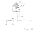
- FIG. 3 shows the finished on the platform 10 lifting device 20 in a first embodiment. It is capable of safely lifting large and heavy loads (eg 100 tons and more) onto the platform 10 from a second delivery means 22 (eg ship or pontoon).
- the loads may be, for example, transformers 25 needed to set up an offshore substation on the platform 10.
- the first embodiment shown comprises two load ropes 24 carrying the load 25 to be carried.
- Each load cable 24 is guided over a trolley 26.
- the two trolleys 26 are each guided on a rail track 28 of the crane 20.
- the rail tracks 28 extend along the boom 19, preferably on an upper side of the boom 19, so that the lifting device 20 can receive and lift loads 25 outside the platform 10 in order subsequently to move and place them in the area of the platform 10.
- upper portion of the crane 20 is given a relatively large clear height H below the trolleys 26, so that even very high loads 25 are moved by the crane 20 on the surface 10 'of the platform 10 without the construction of the crane 20 disproportionately high build have to.
- load ropes e.g. six or eight, as well as appropriate trolleys, are also possible.
- FIG. 4A shows a further embodiment of the lifting device 20.
- the further embodiment has four load cables 24 and thus also four trolleys 26.
- the trolleys 26 are guided on rail tracks 28 along the boom 19, which are preferably arranged on the upper side 19 a of the boom 19. This results in a larger clear height for the Transport of the load 25 against attachment of the rail tracks 28 in a lower portion 19b, so that the load in the part 19c of the boom 19, which is above the platform 10, can be moved, and not only in the cantilever portion 19d of the boom 19th
- the harness 40 may then find application when instead of multiple trolleys 26 ( FIG. 4A ) only one carrying cable 191 ( FIG. 5A ) is used to realize a plurality of attachment points 42 for the load 25.
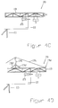
- FIG. 4B shows a side view of an embodiment of the lifting device 20 according to the invention, in which a can be assembled from individual modules boom 19 is arranged relative to the platform 10 so that it partially, namely with its portion 19 d, projects beyond the platform 10.
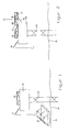
- the lifting device 20 can advantageously also be arranged relative to the platform 10 such that its longitudinal axis 20 'extends at least in sections in the area of an outer platform edge 10', cf. the top view FIG. 4H , In this case, the load 25 can be moved laterally past the platform 10 at least over part of the overall length of the boom 19 become.
- the lifting device 20 can be installed on the platform 10 such that the longitudinal axis 20 'of a cantilever has an arbitrary angle, in particular also acute angles, that is to say an angle of less than 90 °.
- the boom 19 - in certain, due to the design limits - also be formed bent, cf. the top view according to FIG. 4I in that different boom sections 19c, 19d have longitudinal axes (not shown) that do not coincide.
- FIG. 4C shows a side view of another embodiment of the modular lifting device 20 in its installed state on the platform 10.
- the total height H of the boom 19 is relatively low, resulting in a saving of building material for the construction of the lifting device 20 against a variant with greater overall height H.
- the boom 19 can be arranged, for example, directly in the region of the platform edge.
- Figure 4D shows a side view of another embodiment of the modular lifting device 20 in its installed state on the platform 10.
- FIG. 4C shows the variant of the invention Figure 4D in addition to the main boom 19 on a jib 190 in the manner of a derrick crane.
- the auxiliary boom 190 may be either one piece or - like the rest of the lifting device 20 - also be constructed modular and designed, for example, a truss structure or mast-like (substantially cylindrical shape without truss structure).
- the auxiliary boom 190 allows further stabilization of the lifting device 20, because of him or by means of a guided over him pull cable 191 forces from the boom tip 19e to a not in Figure 4D Imaged ballast or anchorage in the platform 10 can be derived, thereby reducing the prevailing in the cantilevered portion of the boom 19 bending moments.
- the auxiliary boom 190 may in turn be stabilized by optional struts 192, wherein the struts 192 may provide a connection between the auxiliary boom 190 and the main boom 190 and / or directly the platform 10.
- the auxiliary boom 190 is preferably stationary fixed, according to another embodiment, but also movable, for example telescopically or rotatably formed and arranged.
- the separate jib 190 may advantageously also already on the platform 10th existing elevated structure with sufficient stability can be used to provide the corresponding function. In this case, it may be sufficient to attach a pulley for guiding the pull cable 191 to the existing structure.
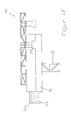
- FIG. 4E shows a side view of another embodiment of the modular lifting device 20 in its installed state on the platform 10.
- a - preferably also modular buildable - ballast tank 20a is provided, for example, with seawater 23 or other suitable fluid or with solid ballast bodies such Concrete blocks or separately filled individual tanks or with free-flowing media can be filled and thus represents a counterweight to the load to be transported 25.
- the level of the ballast tank 20a - especially when using seawater - dynamically adaptable to the current load situation.
- the ballast tank 20a advantageously prevents tensile forces acting on the platform foot 15 or a foot 15 fixing foundation during loading of the load.
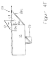
- the lifting device 20 is at least partially formed by carrier elements 20b, 20c, on the one hand modular be attached to the platform 10, on the other hand, however, a Part of the platform 10 can form, that is not constantly need to be set up and removed when needed.
- the carrier elements 20b, 20c could also already be integrated in the platform construction, wherein, in particular, the horizontal carrier 20b can be displaceably arranged on the platform, so that it can be laterally, if necessary FIG. 4F to the right, at least partially moved out of the platform 10 to build the lifting device 20.
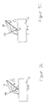
- FIG. 4G Be sufficient to supplement the support members 20b, 20c with trolley means 24, hoisting ropes 24a, etc. and, for example, disassemble a side wall 10a of the platform 10 to unload the load 25 with the lifting means 20 substantially formed by the support members 20b, 20c.
- the dismantling of the side wall 10 a can be done with smaller auxiliary lifting means, such as a conventional stationary crane 12 of the platform 10. That is, the on-board crane 12 is only required, if necessary, to uninstall the side wall 10a and, for example, to build up the additional component 20c and possibly further components of the lifting device 20. Large loads 25 ( FIG. 4G ) are finally moved or loaded again with the lifting device 20.
- FIG. 5A shows a side view of another embodiment of the modular lifting device 20 in its installed state on the platform 10.
- the modular structure lifting device 20 in the manner of a derrick, namely with a main boom 19 and a jib 190, formed.
- the foot points 19f, 190f of the main boom 19 and of the auxiliary jib and a fastening point 191a of the traction cable 191 guided via the auxiliary jib 190 in the structure of the lifting device 20 are selected so that they lie in the region of support structures 15a which are directly connected to the base 15 or the foundation of the platform 10 are connected, whereby a particularly stable structure is created.
- ballast tank can also be used in this embodiment, cf. Figure 4E ,
- FIG. 5A It can be seen, among other things, 191 different arrangements can be selected for the auxiliary boom 190 and the guide of the traction cable, see. the indicated by dashed lines and unspecified components. Also, the mounting point of the pull cable 191 on the main boom 19 can assume various positions, for example, on the boom tip 19e.
- an angle ⁇ between the main boom 19 and the auxiliary boom 190 is constant.
- a fastenable to the harness 40 load (not shown), for example, thereby be moved vertically, inter alia, that in the region of the attachment point 191a a winch is arranged, the pull rope 191 off and can wind up.
- the crane 20 for example, about an approximately perpendicular to the plane of the FIG. 5A and in the area of the foot point 190f lying axis are rotated.
- FIG. 5B shows a side view of another embodiment of the modular lifting device 20, which has a main boom 19 and a jib 190.
- the attachment points of the arms 19, 190 are preferably as in FIG. 5B
- FIG. 5A selected.
- an angle ⁇ 1 between the auxiliary boom 190 and a plane defined by the platform surface 10b is constant.
- FIGS. 5C and 5D each show a side view of another embodiment of the modular built-up lifting device 20, wherein the auxiliary boom 190 are optionally formed telescopic.
- the angles ⁇ , ⁇ 1 are designed to be constant according to a preferred embodiment.
- FIG. 5F is the attachment point 191a for the platform-side end of the pull cable 191 formed movable, which can be realized for example by means of a track or trolley.
- the tensile force coupled into the platform 10 by the cable 191 is advantageously controllable with respect to its point of application on the platform.
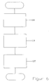
- FIG. 6 shows an embodiment of the method according to the invention.
- step 100 a plurality of individual modules 18 (FIG. FIG. 1 ) of the lifting device 20 in the region of the platform 10 by means of the ship 16.
- step 110 a plurality of modules 18 are placed on the platform 10. This means that the individual modules 18 are lifted by the ship 16 and then the modules 18 are unloaded on the platform 10.
- step 120 the modules 18 are assembled in the required order to the lifting device 20.
- the lifting device 20, preferably in inverse order for assembly - be dismantled again.
- the invention offers the other advantages of high availability and predictability and less weather dependence, because the loading individual crane modules 18 by arranged on the platform 10 auxiliary lifting means 12 is feasible even in heavy seas.
- the principle according to the invention also makes it possible to provide, at least temporarily, high-load cranes 20 on a platform 10 which have a lifting capacity which exceeds that of floating cranes.
- a modular high-load crane 20 temporarily on the platform 10, which has a lifting capacity of several hundred tons, while implementing the principle according to the invention. After use on the platform 10, the high load crane 20 may be dismantled from the platform 10 and deployed elsewhere.
- FIG. 7 shows a further embodiment in which the modular buildable high-load crane 20 extends with its boom at least substantially along the entire platform width B (in addition to over the platform edge projecting part 20 'of the boom), so that loads 25 not only predominantly vertical, eg From ships to the platform 10 and vice versa, movable, but also horizontally over wide areas of the platform surface are movable, see. the in the FIG. 6 left area of the platform standing unloaded transformer 25th
Landscapes
- Engineering & Computer Science (AREA)
- Mechanical Engineering (AREA)
- Jib Cranes (AREA)
- Ship Loading And Unloading (AREA)
Applications Claiming Priority (1)
| Application Number | Priority Date | Filing Date | Title |
|---|---|---|---|
| DE201010019492 DE102010019492A1 (de) | 2010-04-29 | 2010-04-29 | Verfahren zum Bereitstellen einer Hebevorrichtung auf einer Plattform |
Publications (3)
| Publication Number | Publication Date |
|---|---|
| EP2383219A2 true EP2383219A2 (fr) | 2011-11-02 |
| EP2383219A3 EP2383219A3 (fr) | 2013-10-23 |
| EP2383219B1 EP2383219B1 (fr) | 2016-11-02 |
Family
ID=44117647
Family Applications (1)
| Application Number | Title | Priority Date | Filing Date |
|---|---|---|---|
| EP11164157.7A Active EP2383219B1 (fr) | 2010-04-29 | 2011-04-28 | Procédé de préparation d'un dispositif de levage sur une plate-forme |
Country Status (2)
| Country | Link |
|---|---|
| EP (1) | EP2383219B1 (fr) |
| DE (1) | DE102010019492A1 (fr) |
Cited By (4)
| Publication number | Priority date | Publication date | Assignee | Title |
|---|---|---|---|---|
| WO2014040928A1 (fr) * | 2012-09-12 | 2014-03-20 | Terex Cranes Germany Gmbh | Système de réduction de contrepoids d'une grue |
| WO2014146898A1 (fr) * | 2013-03-21 | 2014-09-25 | Senvion Se | Système et procédé pour le transport et le test d'une grue destinée à être utilisée dans une installation éolienne marine |
| CN104310235A (zh) * | 2014-09-25 | 2015-01-28 | 太平洋海洋工程(舟山)有限公司 | 海工生活平台上建整体吊运方法 |
| CN108216513A (zh) * | 2018-02-26 | 2018-06-29 | 黄诚 | 海上工程化平台 |
Family Cites Families (5)
| Publication number | Priority date | Publication date | Assignee | Title |
|---|---|---|---|---|
| US4535900A (en) * | 1983-04-25 | 1985-08-20 | Fluor Corporation | Transfer apparatus and method |
| DE4305620A1 (de) * | 1993-02-24 | 1994-08-25 | Krupp Foerdertechnik Gmbh | Verfahren zur Herstellung und Montage von Kranen sowie Kran, insbesondere Bordkran |
| WO1997031855A1 (fr) * | 1996-02-29 | 1997-09-04 | Mammoet Decalift International B.V. | Dispositif de levage |
| FR2822890B1 (fr) * | 2001-03-30 | 2003-10-31 | Cammell Laird Marseille | Procede d'installation des appareils de forage sur les plates-formes offshore et appareils de forage resultant de la mise en oeuvre de ce procede |
| EP1492699B1 (fr) * | 2002-04-10 | 2007-08-01 | Itrec B.V. | Navire submersible |
-
2010
- 2010-04-29 DE DE201010019492 patent/DE102010019492A1/de not_active Withdrawn
-
2011
- 2011-04-28 EP EP11164157.7A patent/EP2383219B1/fr active Active
Non-Patent Citations (1)
| Title |
|---|
| None |
Cited By (10)
| Publication number | Priority date | Publication date | Assignee | Title |
|---|---|---|---|---|
| WO2014040928A1 (fr) * | 2012-09-12 | 2014-03-20 | Terex Cranes Germany Gmbh | Système de réduction de contrepoids d'une grue |
| EP3002246A1 (fr) * | 2012-09-12 | 2016-04-06 | Terex Cranes Germany GmbH | Système pour réduire le contrepoids d'une grue |
| US9556007B2 (en) | 2012-09-12 | 2017-01-31 | Terex Cranes Germany Gmbh | System for rearranging the counterweight of a crane operation |
| WO2014146898A1 (fr) * | 2013-03-21 | 2014-09-25 | Senvion Se | Système et procédé pour le transport et le test d'une grue destinée à être utilisée dans une installation éolienne marine |
| CN105164043A (zh) * | 2013-03-21 | 2015-12-16 | 森维安欧洲股份公司 | 用于运输和测试旨在用于离岸风力涡轮机中的起重机的系统和方法 |
| CN105164043B (zh) * | 2013-03-21 | 2017-05-10 | 森维安欧洲股份公司 | 用于运输和测试旨在用于离岸风力涡轮机中的起重机的系统和方法 |
| US9944503B2 (en) | 2013-03-21 | 2018-04-17 | Senvion Se | System and method for transporting and testing a crane intended for use in an offshore wind turbine |
| CN104310235A (zh) * | 2014-09-25 | 2015-01-28 | 太平洋海洋工程(舟山)有限公司 | 海工生活平台上建整体吊运方法 |
| CN108216513A (zh) * | 2018-02-26 | 2018-06-29 | 黄诚 | 海上工程化平台 |
| CN108216513B (zh) * | 2018-02-26 | 2023-11-14 | 黄诚 | 海上工程化平台 |
Also Published As
| Publication number | Publication date |
|---|---|
| EP2383219A3 (fr) | 2013-10-23 |
| DE102010019492A1 (de) | 2011-11-03 |
| EP2383219B1 (fr) | 2016-11-02 |
Similar Documents
| Publication | Publication Date | Title |
|---|---|---|
| EP2436593B1 (fr) | Bateau et procédé de transport et d'établissement de structures offshore | |
| DE60126984T2 (de) | Verfahren und vorrichtung zur anordnung mindestens einer windturbine an offenem wasser | |
| DE60034695T2 (de) | Methode und einrichtung zum transport und zum aufbau einer windenergieanlage auf see | |
| DE2345274A1 (de) | Hebbare hochseeplattform | |
| EP2539219B1 (fr) | Dispositif pour le transport et l'installation d'un agencement d'une éolienne offshore comprenant une embase et procédé pour le transport et l'installation d'un tel agencement muni d'une embase | |
| EP4127453B1 (fr) | Procédé de montage d'une éolienne comprenant une tour et deux flèches s'étendant à partir de la tour | |
| EP3428345A1 (fr) | Fondation pour une éolienne en mer | |
| EP2591176B1 (fr) | Installation en mer, en particulier éolienne | |
| WO2018054532A1 (fr) | Ouvrage destiné à être érigé à la surface d'étendues d'eau et procédé pour son érection | |
| EP2383219B1 (fr) | Procédé de préparation d'un dispositif de levage sur une plate-forme | |
| DE60101160T2 (de) | Fördersystem für lasten | |
| DE2726407A1 (de) | Verfahren zum ein- und ausbringen von schweren objekten in ein oder aus einem schiff sowie vorrichtung zur durchfuehrung dieses verfahrens | |
| DE2334468A1 (de) | Verfahren zur herstellung grosser schwimmender einheiten | |
| DE2840720A1 (de) | Verfahren fuer den bau und den transport von teilen eines maritimen bauwerks und fahrzeug fuer die verwendung in diesem verfahren | |
| DE202021102426U1 (de) | Off-Shore-Windenergieanlagen-Aufbau-Schiff | |
| EP2623674A1 (fr) | Infrastructure pour une plateforme offshore et procédé d'installation d'une telle infrastructure | |
| DE2457536C3 (de) | Verfahren zum Transport und zum Absetzen einer Offshore-Plattform auf der Meeressohle sowie Offshore-Plattform | |
| EP2396537B1 (fr) | Équipement et procédé pour la fabrication d'installations aérogénératrices en mer | |
| DE102010015412A1 (de) | Verfahren zum Transport und zur Montage einer Windkraftanlage und Transport- und Montagesystem | |
| EP2623675A1 (fr) | Partie supérieure d'une plateforme offshore et procédé d'installation d'une telle partie supérieure d'une plateforme | |
| DE102011109251A1 (de) | Katamaran-Ponton | |
| WO2010115933A2 (fr) | Procédé d'érection d'une installation offshore et installation offshore | |
| DE102021111680B4 (de) | Off-shore-windenergieanlagen-aufbau-schiff sowie off-shorewindenergieanlagen- aufbau-verfahren | |
| EP1565619B1 (fr) | Dispositif pour amarrer un bateau a un batiment maritime | |
| WO2011138195A1 (fr) | Bâti de base pour une plate-forme offshore à mise en place automatique |
Legal Events
| Date | Code | Title | Description |
|---|---|---|---|
| AK | Designated contracting states |
Kind code of ref document: A2 Designated state(s): AL AT BE BG CH CY CZ DE DK EE ES FI FR GB GR HR HU IE IS IT LI LT LU LV MC MK MT NL NO PL PT RO RS SE SI SK SM TR |
|
| AX | Request for extension of the european patent |
Extension state: BA ME |
|
| PUAI | Public reference made under article 153(3) epc to a published international application that has entered the european phase |
Free format text: ORIGINAL CODE: 0009012 |
|
| PUAL | Search report despatched |
Free format text: ORIGINAL CODE: 0009013 |
|
| AK | Designated contracting states |
Kind code of ref document: A3 Designated state(s): AL AT BE BG CH CY CZ DE DK EE ES FI FR GB GR HR HU IE IS IT LI LT LU LV MC MK MT NL NO PL PT RO RS SE SI SK SM TR |
|
| AX | Request for extension of the european patent |
Extension state: BA ME |
|
| RIC1 | Information provided on ipc code assigned before grant |
Ipc: B66C 23/53 20060101ALI20130917BHEP Ipc: B66C 23/18 20060101AFI20130917BHEP Ipc: B66C 23/72 20060101ALI20130917BHEP |
|
| 17P | Request for examination filed |
Effective date: 20140422 |
|
| RBV | Designated contracting states (corrected) |
Designated state(s): AL AT BE BG CH CY CZ DE DK EE ES FI FR GB GR HR HU IE IS IT LI LT LU LV MC MK MT NL NO PL PT RO RS SE SI SK SM TR |
|
| 17Q | First examination report despatched |
Effective date: 20140709 |
|
| RAP1 | Party data changed (applicant data changed or rights of an application transferred) |
Owner name: ALSTOM GRID GMBH |
|
| RAP1 | Party data changed (applicant data changed or rights of an application transferred) |
Owner name: ALSTOM TECHNOLOGY LTD |
|
| GRAP | Despatch of communication of intention to grant a patent |
Free format text: ORIGINAL CODE: EPIDOSNIGR1 |
|
| INTG | Intention to grant announced |
Effective date: 20160519 |
|
| GRAS | Grant fee paid |
Free format text: ORIGINAL CODE: EPIDOSNIGR3 |
|
| RIN1 | Information on inventor provided before grant (corrected) |
Inventor name: MARBURG, DIETER Inventor name: HOEPFNER, SVEN Inventor name: SCHOLZ, EDGAR |
|
| GRAA | (expected) grant |
Free format text: ORIGINAL CODE: 0009210 |
|
| RAP1 | Party data changed (applicant data changed or rights of an application transferred) |
Owner name: GENERAL ELECTRIC TECHNOLOGY GMBH |
|
| AK | Designated contracting states |
Kind code of ref document: B1 Designated state(s): AL AT BE BG CH CY CZ DE DK EE ES FI FR GB GR HR HU IE IS IT LI LT LU LV MC MK MT NL NO PL PT RO RS SE SI SK SM TR |
|
| REG | Reference to a national code |
Ref country code: GB Ref legal event code: FG4D Free format text: NOT ENGLISH |
|
| REG | Reference to a national code |
Ref country code: AT Ref legal event code: REF Ref document number: 841627 Country of ref document: AT Kind code of ref document: T Effective date: 20161115 Ref country code: CH Ref legal event code: EP |
|
| REG | Reference to a national code |
Ref country code: IE Ref legal event code: FG4D Free format text: LANGUAGE OF EP DOCUMENT: GERMAN |
|
| REG | Reference to a national code |
Ref country code: DE Ref legal event code: R096 Ref document number: 502011011030 Country of ref document: DE |
|
| REG | Reference to a national code |
Ref country code: NL Ref legal event code: FP |
|
| PG25 | Lapsed in a contracting state [announced via postgrant information from national office to epo] |
Ref country code: LV Free format text: LAPSE BECAUSE OF FAILURE TO SUBMIT A TRANSLATION OF THE DESCRIPTION OR TO PAY THE FEE WITHIN THE PRESCRIBED TIME-LIMIT Effective date: 20161102 |
|
| REG | Reference to a national code |
Ref country code: LT Ref legal event code: MG4D |
|
| REG | Reference to a national code |
Ref country code: FR Ref legal event code: PLFP Year of fee payment: 7 |
|
| PG25 | Lapsed in a contracting state [announced via postgrant information from national office to epo] |
Ref country code: GR Free format text: LAPSE BECAUSE OF FAILURE TO SUBMIT A TRANSLATION OF THE DESCRIPTION OR TO PAY THE FEE WITHIN THE PRESCRIBED TIME-LIMIT Effective date: 20170203 Ref country code: NO Free format text: LAPSE BECAUSE OF FAILURE TO SUBMIT A TRANSLATION OF THE DESCRIPTION OR TO PAY THE FEE WITHIN THE PRESCRIBED TIME-LIMIT Effective date: 20170202 Ref country code: SE Free format text: LAPSE BECAUSE OF FAILURE TO SUBMIT A TRANSLATION OF THE DESCRIPTION OR TO PAY THE FEE WITHIN THE PRESCRIBED TIME-LIMIT Effective date: 20161102 Ref country code: LT Free format text: LAPSE BECAUSE OF FAILURE TO SUBMIT A TRANSLATION OF THE DESCRIPTION OR TO PAY THE FEE WITHIN THE PRESCRIBED TIME-LIMIT Effective date: 20161102 |
|
| PG25 | Lapsed in a contracting state [announced via postgrant information from national office to epo] |
Ref country code: HR Free format text: LAPSE BECAUSE OF FAILURE TO SUBMIT A TRANSLATION OF THE DESCRIPTION OR TO PAY THE FEE WITHIN THE PRESCRIBED TIME-LIMIT Effective date: 20161102 Ref country code: RS Free format text: LAPSE BECAUSE OF FAILURE TO SUBMIT A TRANSLATION OF THE DESCRIPTION OR TO PAY THE FEE WITHIN THE PRESCRIBED TIME-LIMIT Effective date: 20161102 Ref country code: PL Free format text: LAPSE BECAUSE OF FAILURE TO SUBMIT A TRANSLATION OF THE DESCRIPTION OR TO PAY THE FEE WITHIN THE PRESCRIBED TIME-LIMIT Effective date: 20161102 Ref country code: FI Free format text: LAPSE BECAUSE OF FAILURE TO SUBMIT A TRANSLATION OF THE DESCRIPTION OR TO PAY THE FEE WITHIN THE PRESCRIBED TIME-LIMIT Effective date: 20161102 Ref country code: IS Free format text: LAPSE BECAUSE OF FAILURE TO SUBMIT A TRANSLATION OF THE DESCRIPTION OR TO PAY THE FEE WITHIN THE PRESCRIBED TIME-LIMIT Effective date: 20170302 Ref country code: PT Free format text: LAPSE BECAUSE OF FAILURE TO SUBMIT A TRANSLATION OF THE DESCRIPTION OR TO PAY THE FEE WITHIN THE PRESCRIBED TIME-LIMIT Effective date: 20170302 Ref country code: ES Free format text: LAPSE BECAUSE OF FAILURE TO SUBMIT A TRANSLATION OF THE DESCRIPTION OR TO PAY THE FEE WITHIN THE PRESCRIBED TIME-LIMIT Effective date: 20161102 |
|
| PG25 | Lapsed in a contracting state [announced via postgrant information from national office to epo] |
Ref country code: SK Free format text: LAPSE BECAUSE OF FAILURE TO SUBMIT A TRANSLATION OF THE DESCRIPTION OR TO PAY THE FEE WITHIN THE PRESCRIBED TIME-LIMIT Effective date: 20161102 Ref country code: CZ Free format text: LAPSE BECAUSE OF FAILURE TO SUBMIT A TRANSLATION OF THE DESCRIPTION OR TO PAY THE FEE WITHIN THE PRESCRIBED TIME-LIMIT Effective date: 20161102 Ref country code: DK Free format text: LAPSE BECAUSE OF FAILURE TO SUBMIT A TRANSLATION OF THE DESCRIPTION OR TO PAY THE FEE WITHIN THE PRESCRIBED TIME-LIMIT Effective date: 20161102 Ref country code: RO Free format text: LAPSE BECAUSE OF FAILURE TO SUBMIT A TRANSLATION OF THE DESCRIPTION OR TO PAY THE FEE WITHIN THE PRESCRIBED TIME-LIMIT Effective date: 20161102 Ref country code: EE Free format text: LAPSE BECAUSE OF FAILURE TO SUBMIT A TRANSLATION OF THE DESCRIPTION OR TO PAY THE FEE WITHIN THE PRESCRIBED TIME-LIMIT Effective date: 20161102 |
|
| REG | Reference to a national code |
Ref country code: DE Ref legal event code: R097 Ref document number: 502011011030 Country of ref document: DE |
|
| PG25 | Lapsed in a contracting state [announced via postgrant information from national office to epo] |
Ref country code: SM Free format text: LAPSE BECAUSE OF FAILURE TO SUBMIT A TRANSLATION OF THE DESCRIPTION OR TO PAY THE FEE WITHIN THE PRESCRIBED TIME-LIMIT Effective date: 20161102 Ref country code: BG Free format text: LAPSE BECAUSE OF FAILURE TO SUBMIT A TRANSLATION OF THE DESCRIPTION OR TO PAY THE FEE WITHIN THE PRESCRIBED TIME-LIMIT Effective date: 20170202 Ref country code: IT Free format text: LAPSE BECAUSE OF FAILURE TO SUBMIT A TRANSLATION OF THE DESCRIPTION OR TO PAY THE FEE WITHIN THE PRESCRIBED TIME-LIMIT Effective date: 20161102 |
|
| PLBE | No opposition filed within time limit |
Free format text: ORIGINAL CODE: 0009261 |
|
| STAA | Information on the status of an ep patent application or granted ep patent |
Free format text: STATUS: NO OPPOSITION FILED WITHIN TIME LIMIT |
|
| 26N | No opposition filed |
Effective date: 20170803 |
|
| PG25 | Lapsed in a contracting state [announced via postgrant information from national office to epo] |
Ref country code: SI Free format text: LAPSE BECAUSE OF FAILURE TO SUBMIT A TRANSLATION OF THE DESCRIPTION OR TO PAY THE FEE WITHIN THE PRESCRIBED TIME-LIMIT Effective date: 20161102 |
|
| REG | Reference to a national code |
Ref country code: CH Ref legal event code: PL |
|
| REG | Reference to a national code |
Ref country code: IE Ref legal event code: MM4A |
|
| PG25 | Lapsed in a contracting state [announced via postgrant information from national office to epo] |
Ref country code: MC Free format text: LAPSE BECAUSE OF FAILURE TO SUBMIT A TRANSLATION OF THE DESCRIPTION OR TO PAY THE FEE WITHIN THE PRESCRIBED TIME-LIMIT Effective date: 20161102 |
|
| PG25 | Lapsed in a contracting state [announced via postgrant information from national office to epo] |
Ref country code: LU Free format text: LAPSE BECAUSE OF NON-PAYMENT OF DUE FEES Effective date: 20170428 Ref country code: LI Free format text: LAPSE BECAUSE OF NON-PAYMENT OF DUE FEES Effective date: 20170430 Ref country code: CH Free format text: LAPSE BECAUSE OF NON-PAYMENT OF DUE FEES Effective date: 20170430 |
|
| REG | Reference to a national code |
Ref country code: FR Ref legal event code: PLFP Year of fee payment: 8 |
|
| PG25 | Lapsed in a contracting state [announced via postgrant information from national office to epo] |
Ref country code: IE Free format text: LAPSE BECAUSE OF NON-PAYMENT OF DUE FEES Effective date: 20170428 |
|
| REG | Reference to a national code |
Ref country code: AT Ref legal event code: MM01 Ref document number: 841627 Country of ref document: AT Kind code of ref document: T Effective date: 20170428 |
|
| PG25 | Lapsed in a contracting state [announced via postgrant information from national office to epo] |
Ref country code: AT Free format text: LAPSE BECAUSE OF NON-PAYMENT OF DUE FEES Effective date: 20170428 |
|
| PG25 | Lapsed in a contracting state [announced via postgrant information from national office to epo] |
Ref country code: MT Free format text: LAPSE BECAUSE OF FAILURE TO SUBMIT A TRANSLATION OF THE DESCRIPTION OR TO PAY THE FEE WITHIN THE PRESCRIBED TIME-LIMIT Effective date: 20161102 |
|
| PG25 | Lapsed in a contracting state [announced via postgrant information from national office to epo] |
Ref country code: HU Free format text: LAPSE BECAUSE OF FAILURE TO SUBMIT A TRANSLATION OF THE DESCRIPTION OR TO PAY THE FEE WITHIN THE PRESCRIBED TIME-LIMIT; INVALID AB INITIO Effective date: 20110428 |
|
| PG25 | Lapsed in a contracting state [announced via postgrant information from national office to epo] |
Ref country code: CY Free format text: LAPSE BECAUSE OF NON-PAYMENT OF DUE FEES Effective date: 20161102 |
|
| PG25 | Lapsed in a contracting state [announced via postgrant information from national office to epo] |
Ref country code: MK Free format text: LAPSE BECAUSE OF FAILURE TO SUBMIT A TRANSLATION OF THE DESCRIPTION OR TO PAY THE FEE WITHIN THE PRESCRIBED TIME-LIMIT Effective date: 20161102 |
|
| PG25 | Lapsed in a contracting state [announced via postgrant information from national office to epo] |
Ref country code: TR Free format text: LAPSE BECAUSE OF FAILURE TO SUBMIT A TRANSLATION OF THE DESCRIPTION OR TO PAY THE FEE WITHIN THE PRESCRIBED TIME-LIMIT Effective date: 20161102 |
|
| PG25 | Lapsed in a contracting state [announced via postgrant information from national office to epo] |
Ref country code: AL Free format text: LAPSE BECAUSE OF FAILURE TO SUBMIT A TRANSLATION OF THE DESCRIPTION OR TO PAY THE FEE WITHIN THE PRESCRIBED TIME-LIMIT Effective date: 20161102 |
|
| P01 | Opt-out of the competence of the unified patent court (upc) registered |
Effective date: 20230522 |
|
| PGFP | Annual fee paid to national office [announced via postgrant information from national office to epo] |
Ref country code: DE Payment date: 20250319 Year of fee payment: 15 |
|
| PGFP | Annual fee paid to national office [announced via postgrant information from national office to epo] |
Ref country code: GB Payment date: 20260319 Year of fee payment: 16 |
|
| PGFP | Annual fee paid to national office [announced via postgrant information from national office to epo] |
Ref country code: BE Payment date: 20260319 Year of fee payment: 16 |
|
| PGFP | Annual fee paid to national office [announced via postgrant information from national office to epo] |
Ref country code: NL Payment date: 20260319 Year of fee payment: 16 |
|
| PGFP | Annual fee paid to national office [announced via postgrant information from national office to epo] |
Ref country code: FR Payment date: 20260320 Year of fee payment: 16 |