EP2383221B1 - Gripping device for automatic bottle-topping machines - Google Patents
Gripping device for automatic bottle-topping machines Download PDFInfo
- Publication number
- EP2383221B1 EP2383221B1 EP10192903.2A EP10192903A EP2383221B1 EP 2383221 B1 EP2383221 B1 EP 2383221B1 EP 10192903 A EP10192903 A EP 10192903A EP 2383221 B1 EP2383221 B1 EP 2383221B1
- Authority
- EP
- European Patent Office
- Prior art keywords
- gripping
- rocker
- articulation
- turn
- axis
- Prior art date
- Legal status (The legal status is an assumption and is not a legal conclusion. Google has not performed a legal analysis and makes no representation as to the accuracy of the status listed.)
- Active
Links
Images


Classifications
-
- B—PERFORMING OPERATIONS; TRANSPORTING
- B67—OPENING, CLOSING OR CLEANING BOTTLES, JARS OR SIMILAR CONTAINERS; LIQUID HANDLING
- B67C—CLEANING, FILLING WITH LIQUIDS OR SEMILIQUIDS, OR EMPTYING, OF BOTTLES, JARS, CANS, CASKS, BARRELS, OR SIMILAR CONTAINERS, NOT OTHERWISE PROVIDED FOR; FUNNELS
- B67C3/00—Bottling liquids or semiliquids; Filling jars or cans with liquids or semiliquids using bottling or like apparatus; Filling casks or barrels with liquids or semiliquids
- B67C3/02—Bottling liquids or semiliquids; Filling jars or cans with liquids or semiliquids using bottling or like apparatus
- B67C3/22—Details
- B67C3/24—Devices for supporting or handling bottles
- B67C3/242—Devices for supporting or handling bottles engaging with bottle necks
-
- B—PERFORMING OPERATIONS; TRANSPORTING
- B65—CONVEYING; PACKING; STORING; HANDLING THIN OR FILAMENTARY MATERIAL
- B65G—TRANSPORT OR STORAGE DEVICES, e.g. CONVEYORS FOR LOADING OR TIPPING, SHOP CONVEYOR SYSTEMS OR PNEUMATIC TUBE CONVEYORS
- B65G47/00—Article or material-handling devices associated with conveyors; Methods employing such devices
- B65G47/74—Feeding, transfer, or discharging devices of particular kinds or types
- B65G47/84—Star-shaped wheels or devices having endless travelling belts or chains, the wheels or devices being equipped with article-engaging elements
- B65G47/846—Star-shaped wheels or wheels equipped with article-engaging elements
- B65G47/847—Star-shaped wheels or wheels equipped with article-engaging elements the article-engaging elements being grippers
-
- B—PERFORMING OPERATIONS; TRANSPORTING
- B67—OPENING, CLOSING OR CLEANING BOTTLES, JARS OR SIMILAR CONTAINERS; LIQUID HANDLING
- B67B—APPLYING CLOSURE MEMBERS TO BOTTLES JARS, OR SIMILAR CONTAINERS; OPENING CLOSED CONTAINERS
- B67B3/00—Closing bottles, jars or similar containers by applying caps
- B67B3/20—Closing bottles, jars or similar containers by applying caps by applying and rotating preformed threaded caps
- B67B3/206—Means for preventing rotation of the container or cap
Definitions
- the present invention relates to gripping devices for automatic bottle-topping machines. Such devices are known, for example, from EP 1 712 496 A1 disclosing a gripping device according to the preamble of claim 1, US2007/261369 Al and FR 2 774 666 A1 . More precisely, the present invention regards a gripping device designed for installation on a carousel of an automatic bottle-topping machine and designed to withhold a bottle.
- Automatic bottle-topping machines have, in general, a carousel structure comprising a plurality of different devices, each designed to perform a particular function.
- said devices for example, are topping devices and gripping devices.
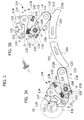
- FIG. 1 Designated by 1 in Figure 1 is an automatic bottle-topping machine of a known type.
- the machine 1 has a vertical axis X about which a plurality of carousels turn, said machine comprising a bottle-holder carousel designated by 2 in Figure 1 .
- the bottle-holder carousel 2 comprises a central star 4, an external guide element 6, and a gripping structure 8.
- the gripping structure 8 comprises a plurality of gripping devices 10.
- Each gripping device 10 comprises an external guide element 12 and an internal centring and blocking element 14.
- a plurality of bottles 16 is carried by the bottle-holder carousel 2 so that the body of the bottles is set in compartments created by the central star 4 and by the external guide element 6, whilst the neck of the bottles is set between the blocking element 14 and the guide element 12.
- each centring and blocking element 14 has a bent lip with a toothed edge 18, which is designed to penetrate in a lip 20 of each bottle 16.
- the machine 1 further comprises a plurality of topping devices 22, particularly of the type with screwing head, positioned so as to be coaxial to a corresponding bottle 16 carried by the bottle-holder carousel 2.
- the bottle-holder carousel 2 turns about the axis X and draws the bottles 16 in rotation.
- the topping devices 22 turn together with the machine 1 and do not vary their relative position with respect to the corresponding bottles 16.
- Each topping device 22 descends towards the corresponding bottle 16 and screws a threaded top or cap on the neck thereof.
- the toothed edge 18 penetrates within the lip 20 following upon a vertical load, directed parallel to the axis X, applied on the bottles 16 by the corresponding topping devices 22.
- the object of the present invention is to overcome the problems of the known art.
- the object of the present invention is to provide a gripping device that is able to block rotation of a bottle without exerting a stress on the lip and is able to eliminate the problems linked to the use of the central star and of the external guide element for guiding each bottle.
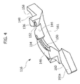
- the device 100 comprises an anti-rotation blocking element 102 (in what follows, for reasons of brevity, referred to as "blocking element") having a pair of teeth 103, a first mechanism 104 provided for actuation of the blocking element 102, a first actuation element 106 operatively connected to the first mechanism 104, a gripping element 108, a second mechanism 110 provided for actuation of the gripping element 108, and a second actuation element 112 operatively connected to the second mechanism 110.
- the device 100 further comprises a main axis of articulation H, a supporting plate 114, which supports the components described previously, and a fixed centring element 116, which is also carried by the plate 114.
- the first actuation element 106 comprises a lever 118 that can turn about the axis H and has a first forked end 120 and a second forked end 122.
- the first forked end 120 is secured, by means of screws 124, on a first pin 126 sharing the axis H and having a hollow cylindrical cross section. In this way, the pin 126 is rigidly connected in rotation to the lever 118.
- a roller 125 is mounted so that it can turn about an axis A parallel to the axis H.
- the first mechanism 104 comprises a first rocker 128, which can turn about the axis H and is rigidly connected in rotation to the pin 126, a first connecting rod 130, articulated, at a first end 132 of its own to the rocker 128, and a second rocker 134, which is articulated to a second end 136 of the connecting rod 130 and is able to turn about an axis B parallel to the axis H.
- the first mechanism 104 further comprises a first elastic element 138 having a first end 140 connected to the first rocker 128 and a second end 142 connected to the supporting plate 114, which supports the second rocker 134.
- the connecting rod 130 is articulated to the first rocker 128 about an axis C parallel to the axis H and is articulated to the second rocker 134 about an axis D parallel to the axis H.
- the axes C and D are mobile with respect to the supporting plate 114, whilst the axes H and B are fixed with respect to the plate 114.
- the first end 140 of the elastic element 138 is mobile with respect to the supporting plate 114, whilst the second end 142 is fixed with respect to the plate 114, and this consequently reflects upon the points of connection of the elastic element 138 to the first rocker 128 and to the plate 114, respectively.
- the blocking element 102 is moreover rigidly connected to the second rocker 134 and turns therewith about the axis B.
- the blocking element 102 is moreover free to slide within the centring element 116.
- the centring element 116 is substantially C-shaped and is designed to co-operate with the elements 102, 108, defining with these a gripping area having variable geometry 143.
- the element 116 comprises a first surface 144, with respect to which two supporting projections 146, 148 with curvilinear development protrude.
- Each supporting projection is shaped in such a way as to comprise a respective supporting surface 150, 152 and a respective conical shoulder 154, 156.
- a similar structure comprising a supporting surface 157 and a conical shoulder 157' is present on the gripping element 108. The latter is preferably hook-shaped.
- recesses 158, 160 having cylindrical walls, whilst present at the supporting projections 146, 148 is a recess with conical wall 161.
- a second surface 161a is moreover provided alongside the projection 146 on a side opposite to the first surface 144.
- the blocking element 102 is positioned between the two projections 146, 148, parallel to the surface 144.
- the first recess with a cylindrical wall 158 receives the connecting rod 130.
- the latter (see Figure 2 ) is preferably made with a pair of identical biscuit-like elements.
- the second actuation element 112 comprises a lever 162, which has a length smaller than the lever 118, is able to turn about the axis H, and has a first forked end 164 and a second forked end 166.
- the first forked end 164 is secured, by means of screws 167, on a second pin 168 sharing the axis H.
- the pin 168 is in this way rigidly connected in rotation to the lever 162 and extends through the entire device 100, being moreover inserted within the first pin 126 ( Figures 3A, 3B ).
- the pins 126, 168 are able to turn independently of one another since no means is provided for inhibiting their relative rotation.
- roller 170 Mounted on the second forked end 166 is a roller 170 that can turn about an axis E parallel to the axis H.
- the second mechanism 110 comprises a third rocker 172, which can turn about the axis H and is rigidly connected in rotation to the pin 168, a second connecting rod 174, articulated, at a first end 176 of its own, to the third rocker 172, and a fourth rocker 178, which can turn about an axis F parallel to the axis H and is articulated to the connecting rod 174 at a second end 180 of the latter.
- the second mechanism 110 further comprises a second elastic element 182 having a first end 184 connected to the third rocker 172, and a second end 186 connected to the fourth rocker 178.
- the third rocker 172 and the connecting rod 174 are articulated with respect to an axis G parallel to the axis H, whilst the fourth rocker 178 and the connecting rod 174 are articulated with respect to an axis I, which is also parallel to the axis H.
- the axis F is fixed with respect to the supporting plate 114, whilst the axes G and I have a position variable with respect to the supporting plate 114.
- the gripping element 108 is rigidly fixed to the rocker 178 by means of screws 188 and is thus itself able to turn about the axis F.
- the second mechanism 110 surmounts the first mechanism 104, from which it is separated by means of a spacer 190 along the axis H and is in turn surmounted by a closing plate 192.
- the plate 192 is fitted on the pin 168 and on a pin 193 sharing the axis F, about which the fourth rocker 178 can turn and connected to which is the second end 186 of the elastic element 182.
- a further pin 194 is rigidly connected to the third rocker 172 and traverses the plate 192 in a position corresponding to a curvilinear groove 196.
- the shape of the groove 196 is such as to enable the motion of the pin 194 about the axis H.
- the fourth rocker 178 has a development, along the axis H, such that it rests on the supporting plate 114.
- the recess 160 is shaped to accommodate the rocker 178.
- the gripping element 108 is supported by the pin 193 in rotation about the axis F.
- each mechanism 104, 110 is mobile between a resting position ( Figures 3A , 5A ) and a working position ( Figures 3B , 5B ).
- the resting position of each of the mechanisms 104, 110 corresponds to a gripping position for both of the elements 102, 108.
- the respective working positions of the mechanisms 104, 110 correspond, instead, to positions of opening of the elements 102, 108.
- the aforesaid blocking and gripping elements 102, 108 co-operate with the centring element 116 for gripping and keeping a bottle 16 fixed in rotation with respect to them. Consequently, the terms "opening position” and “gripping position” evidently refer to the interaction between the device 100 and the bottle 16.
- each of the mechanisms 106, 110 is acuatable by means of rotation of the respective actuation elements 106, 112, particularly of the levers 118, 162.
- the angular staggering of the levers 118, 162 is zero when the mechanisms 104, 110 are in a resting position. Since said levers are rigidly connected in rotation, one to the pin 126 and one to the pin 168, they govern rotation of the first rocker 128 and of the third rocker 172.
- the latter two rockers thanks to the respective kinematic chains, govern the blocking element 102 and the gripping element 108, respectively.
- the passage from the resting position to the working position of the first mechanism 104 is obtained by impressing on the lever 118 a rotation in the direction R illustrated in Figure 3b .
- the direction R is counterclockwise.
- Rotation in the direction R of the lever 118 causes an equal rotation, once again in the direction R, of the first rocker 128.
- This causes a rotation in a direction R', opposite to the direction R, of the connecting rod 130 and a further consequent rotation in the direction R of the second rocker 134.
- the elastic element 138 is set in tension on account of the recession of the end 140 from the end 142.
- Rotation in the direction R of the rocker 134 causes a retraction in a substantially radial direction of the blocking element 102 with respect to the walls of the conical recess 161 of the centring element 116.
- the teeth 103 do not project within the recess with conical wall 161 and are not able to exert any action on the neck of the bottle 16.
- the sizing of the kinematic chain comprising the first and second rockers 128, 134 and the connecting rod 130 is preferably made by selecting lever ratios such that a force impressed on the first rocker 128 is amplified in the transmission to the second rocker 134.
- This aspect is important since it enables the value of stiffness of the elastic element 138 to be kept low.
- the elastic element 138 exerts on the rocker 128 an action of elastic return that causes return of the mechanism 104 into a resting position and consequently blocks the element 102 in the gripping position. Thanks to the amplification of force described above, a force of modest degree exerted by the elastic element 138 is sufficient to transmit to the blocking element 102 a force of greater degree that contributes to maintaining the gripping position.
- Rotation of the lever 162 causes an equal rotation, once again in the direction R (here represented as counterclockwise), of the third rocker 172. This causes a consequent rotation of the connecting rod 174 in the direction R', here represented as clockwise, and finally a rotation once again in the direction R' discordant with respect to the direction R, of the fourth rocker 178, which causes a recession of the gripping element 108 from the supporting projection 146 of the centring element 116 and from the lip 20 of the bottle 16.
- the elastic element 182 is set in tension on account of the recession of the first end 184 from the second end 186.
- the mechanism 110 can return into the resting position thanks to an elastic action provided by the elastic element 182.
- the sizing of the kinematic chain between the third rocker 172 and the fourth rocker 178 is made so that the mechanism 110 is substantially of an irreversible type, i.e., acuatable only by means of one or more very precise elements of the kinematic chain, but not by just any element.
- each mechanism 104, 110 Since the pins 126, 168 are coaxial and are able to turn independently of one another, the actuation of each mechanism 104, 110 is altogether independent and it is possible to have four combinations of the positions of the aforesaid mechanisms, which thus generate four operating configurations of the gripping device 100.
- a plurality of gripping devices 100 is installed on a bottle-topping machine 200 having a carousel structure.
- the machine 200 here represented schematically, co-operates with a loading carousel 202 and an unloading carousel 204.
- the machine 200 is as a whole able to turn about an axis X1, whilst the carousels 202, 204 are able to turn about respective axes X2, X3 parallel to one another and to the axis X1.
- the machine 200 ( Figure 6 and Figures 3 , 5 ) comprises a first cam 206 and a second cam 208 provided for actuation, respectively, of the first mechanism 104 and of the second mechanism 110.
- Each cam 206, 208 has a circular development and comprises a respective path 210, 212 provided for sliding of the rollers 125, 170.
- the path 210 has a radius r210 smaller than the radius r212 of the path 212, but has an angular extension ⁇ 210 greater than the angular extension ⁇ 212 of the path 212.
- Each path 210, 212 comprises, at opposite ends, respective ascending ramps 210a, 212a and descending ramps 210b, 212b. Their functional characterization evidently depends upon the direction of rotation of the machine 200.
- the gripping devices 100 are mounted on the machine 200 in positions set at the same angular distances apart.
- the gripping devices 100 are able to turn with the machine 200 about the axis X1 whilst the cams 208, 206 are fixed in rotation.
- the loading carousel 202 comprises a plurality of gripping assemblies 214, each designed to carry a bottle 16.
- the unloading carousel 204 comprises a plurality of recesses 216, each designed to withhold a respective bottle 16, and a plate 218, which carries the bottles 16.
- the unloading carousel 204 is able to turn about an axis X3 parallel to the axis X1.
- the machine 200, the loading carousel 202, and the unloading carousel 204 define a processing line for the bottles 16.
- the machine 200 and the carousels 202, 204 turn about the respective axes X1, X2, X3.
- the carousels 202 and 204 define with the machine 200 a pair of points of interaction.
- the carousel 202 defines a bottle-loading point L when a gripping device 100 and a gripping assembly 214 occupy a common position, whilst the carousel 204 likewise defines a bottle-unloading point U in the point in which a recess 216 and a gripping device 100 are located in a common position.
- the machine 200 turns about the axis X1 in a direction R1, here represented as being counterclockwise.
- the carousels 202 and 204 turn in directions, respectively, R2 and R3 concordant to one another and opposite to the direction R1.
- the speeds of rotation are such that at each turn the points in which each gripping device shares a common position with a gripping assembly 214 and with a recess 216 have always the same absolute spatial positions, illustrated in Figure 6 .
- the points L and U have fixed positions with respect to the machine 200.
- both of the mechanisms 104, 110 are in the working position since the cams 206, 208 carry out actuation thereof by impressing a rotation on the levers 118, 162. Consequently, the blocking element 102 and the gripping element 108 are in the respective opening positions.
- the bottle 16 passes from a gripping assembly 214 to the gripping device 100.
- the lip 20 rests on the surfaces 150, 152, whilst the oblique shoulders 154, 156 withhold it in position.
- the position of the device 100 with respect to the cams 206, 208 is such that the device occupies a position corresponding to the descending ramp 212b, which is shaped so as to release gradually part of the action on the lever 162, thus causing a progressive closing of the gripping element 108 on the lip 20.
- the device 100 is not yet in a position corresponding to the descending ramp 210b; consequently, the blocking element 102 is still in the open position.
- the element 102 exerts a gripping action on the neck of the bottle 16, thus preventing rotation thereof with respect to the gripping device 100.
- cams 206, 208 immediately downstream of the point L, carry out sequential closing of the gripping element 108 and of the blocking element 102.
- the bottle In the remaining part of the rotation, the bottle is carried by the fixed centring element 116 and is blocked in rotation by the blocking element 102, thus enabling screwing of the top by the device 22 without any possibility of the bottle turning thus annulling the screwing action.
- the cams 206, 208 carry out a sequential opening of the blocking element 102 and of the gripping element 108.
- the device 100 encounters first the cam 206 and the ascending ramp 210a, which operate the lever 118 causing rotation thereof in the direction R and causing opening of the blocking element 102, and then, proceeding further towards the bottle-unloading point U, the device 100 encounters the cam 208 and the ascending ramp 212a, which causes actuation of the lever 162 and consequent opening of the gripping element 108.
- the unloading carousel 204 can pick up the bottle 16, without there being any interference with the gripping device 100.
- the centring element 116 exerts a dual function of supporting the bottle with the surfaces 150 and 152 and of withholding it via the oblique shoulders 154, 156, which enables elimination of the central star 4 and the external guide element 6. Furthermore, the element 116 does not need to be adapted to bottles of different size.
- the action of the anti-rotation blocking element 102 is exerted on the neck of the bottle 16, and neither the lip 20 or the thread undergoes any stress or strain, as occurs in devices of a known type.
- the amplification of force provided by the mechanism 104 involves only modest forces of actuation, which correspond to low values of load on the roller 125.
- the elastic element 182 thus functions as mere means of elastic return, as does the elastic element 138.
Landscapes
- Engineering & Computer Science (AREA)
- Mechanical Engineering (AREA)
- Filling Of Jars Or Cans And Processes For Cleaning And Sealing Jars (AREA)
- Specific Conveyance Elements (AREA)
- Sealing Of Jars (AREA)
Applications Claiming Priority (1)
| Application Number | Priority Date | Filing Date | Title |
|---|---|---|---|
| ITTO2010A000367A IT1399982B1 (it) | 2010-04-30 | 2010-04-30 | Dispositivo di presa per macchine tappatrici automatiche |
Publications (2)
| Publication Number | Publication Date |
|---|---|
| EP2383221A1 EP2383221A1 (en) | 2011-11-02 |
| EP2383221B1 true EP2383221B1 (en) | 2013-07-31 |
Family
ID=43228004
Family Applications (1)
| Application Number | Title | Priority Date | Filing Date |
|---|---|---|---|
| EP10192903.2A Active EP2383221B1 (en) | 2010-04-30 | 2010-11-29 | Gripping device for automatic bottle-topping machines |
Country Status (7)
| Country | Link |
|---|---|
| US (1) | US8439413B2 (it) |
| EP (1) | EP2383221B1 (it) |
| CN (1) | CN102234022B (it) |
| ES (1) | ES2430242T3 (it) |
| IT (1) | IT1399982B1 (it) |
| PT (1) | PT2383221E (it) |
| TW (1) | TWI551517B (it) |
Families Citing this family (21)
| Publication number | Priority date | Publication date | Assignee | Title |
|---|---|---|---|---|
| DE102009050393B4 (de) * | 2009-10-22 | 2011-07-28 | KHS GmbH, 44143 | Behälterklammer bzw. -clip |
| DE102011116883A1 (de) * | 2011-04-21 | 2012-10-25 | Khs Corpoplast Gmbh | Vorrichtung zur Halterung von Werkstücken |
| DE102012206944A1 (de) * | 2012-04-26 | 2013-10-31 | Krones Ag | Vorrichtung zum Verschließen von Kunststoffflaschen |
| US8672376B1 (en) * | 2012-11-16 | 2014-03-18 | Morrison Container Handling Solutions, Inc. | Gripping device |
| CN103848381B (zh) * | 2012-11-30 | 2015-12-09 | 上海赛东科技有限公司 | 可调式灌装机瓶托 |
| FR3004982B1 (fr) * | 2013-04-24 | 2015-05-01 | Serac Group | Dispositif de maintien d'un recipient comprenant une lame ressort et installation de traitement de recipients comprenant un tel dispositif |
| DE102014105907A1 (de) * | 2014-04-28 | 2015-10-29 | Krones Ag | Vorrichtung und Verfahren zum Verschließen befüllter Behälter mit einem Schraubverschluss |
| FR3023273B1 (fr) * | 2014-07-02 | 2016-08-12 | Serac Group | Installation de transport de recipients |
| EP3372553B1 (en) * | 2015-11-04 | 2021-03-24 | Hangzhou Youngsun Intelligent Equipment Co., Ltd. | Bottle conveyor, bottle gripper mechanism for filling machine |
| CN106276235B (zh) * | 2016-09-13 | 2018-08-10 | 河南理工大学 | 一种带有二级推送功能的圆柱物料抓持输送装置 |
| IT201600130755A1 (it) | 2016-12-23 | 2018-06-23 | Arol Spa | Gruppo di azionamento per testa di tappatura e testa di tappatura impiegante lo stesso |
| IT201700011057A1 (it) | 2017-02-01 | 2018-08-01 | Arol Spa | Gruppo di misura di coppia di torsione e/o carico assiale per teste di tappatura |
| IT201700047740A1 (it) * | 2017-05-03 | 2018-11-03 | Arol Spa | Dispositivo di presa e centraggio di bottiglie per impianti di tappatura |
| IT201800003295A1 (it) * | 2018-03-06 | 2019-09-06 | Smi Spa | Dispositivo di manipolazione di contenitori dotato di pinze ad apertura comandata |
| DE102018121092A1 (de) * | 2018-08-29 | 2020-03-05 | Khs Gmbh | Vorrichtung zum Greifen von Behältern |
| CN108994792B (zh) * | 2018-09-27 | 2021-05-18 | 国网四川射洪县供电有限责任公司 | 用于立式水轮机转动部分的荷重转移或提升系统 |
| IT202000014836A1 (it) * | 2020-06-22 | 2021-12-22 | Arol Spa | Dispositivo di manipolazione di contenitori per impianti di tappatura |
| CN114074896B (zh) * | 2020-08-12 | 2024-08-02 | 系统科技公司 | 集成的联接模块和包括该集成的联接模块的联接系统 |
| CN113954116B (zh) * | 2021-10-21 | 2024-06-07 | 江苏新美星包装机械股份有限公司 | 一种自定心容器抓手 |
| CN114939882B (zh) * | 2022-07-25 | 2022-11-04 | 杭州申昊科技股份有限公司 | 一种机械臂末端工具对接机构 |
| CN116750482B (zh) * | 2023-06-20 | 2026-03-31 | 贝尔智能装备(南通)有限公司 | 一种固定卡口式桶装水瓶提瓶机 |
Family Cites Families (15)
| Publication number | Priority date | Publication date | Assignee | Title |
|---|---|---|---|---|
| US3948552A (en) * | 1975-01-08 | 1976-04-06 | Hamrick Gene H | Bottle gripping apparatus |
| US4709803A (en) * | 1986-02-12 | 1987-12-01 | B & G Machinery Company | Preform transfer mechanism |
| CH672955A5 (it) * | 1987-05-12 | 1990-01-15 | Elpatronic Ag | |
| FR2660917B1 (fr) * | 1990-04-11 | 1992-11-20 | Perrier Rene | Pince de prehension et machine de traitement d'objets, notamment de bouteilles, ainsi equipee. |
| US5575379A (en) * | 1993-06-17 | 1996-11-19 | Gammerler Maschinenbau Und Anlagentechnik Gmbh | Newspaper conveyor |
| DE4332342A1 (de) * | 1993-09-23 | 1995-03-30 | Kronseder Maschf Krones | Verfahren und Packmaschine zum Entnehmen von Gefäßen aus Transportbehältern |
| IT1289906B1 (it) * | 1997-01-16 | 1998-10-19 | S B R S R L | Pinza di afferraggio di contenitori quali in particolare bottiglie |
| FR2774666B1 (fr) * | 1998-02-12 | 2000-04-07 | Sidel Sa | Dispositif de transfert pour corps creux possedant un goulot |
| US6248954B1 (en) * | 1999-02-25 | 2001-06-19 | Cable Design Technologies, Inc. | Multi-pair data cable with configurable core filling and pair separation |
| ATE296230T1 (de) * | 1999-04-30 | 2005-06-15 | Krones Ag | Verfahren und vorrichtung zum aufbringen von etikettenhülsen auf gegenstände |
| ITRM20020147A1 (it) * | 2002-03-18 | 2003-09-18 | Sipa Spa | Dispositivo di presa a pinza per bottiglie e simili. |
| US7264113B2 (en) * | 2003-11-13 | 2007-09-04 | Hartness International, Inc. | Pivotable conveyor and link |
| FR2884450B1 (fr) * | 2005-04-15 | 2007-06-22 | Serac Group Soc Par Actions Si | Dispositif de prehension d'un recipient avec maintien d'une partie epaulee de celui-ci |
| US20070261369A1 (en) * | 2006-05-09 | 2007-11-15 | Toyo Seikan Kaisha, Ltd. | Bottle turn prevention mechanism for neck grippers |
| US20070267882A1 (en) * | 2006-05-22 | 2007-11-22 | Toyo Seikan Kaisha Ltd. | Gripping device |
-
2010
- 2010-04-30 IT ITTO2010A000367A patent/IT1399982B1/it active
- 2010-11-26 TW TW099141083A patent/TWI551517B/zh not_active IP Right Cessation
- 2010-11-29 PT PT101929032T patent/PT2383221E/pt unknown
- 2010-11-29 ES ES10192903T patent/ES2430242T3/es active Active
- 2010-11-29 EP EP10192903.2A patent/EP2383221B1/en active Active
-
2011
- 2011-01-28 US US13/016,799 patent/US8439413B2/en not_active Expired - Fee Related
- 2011-01-31 CN CN201110033394.7A patent/CN102234022B/zh not_active Expired - Fee Related
Also Published As
| Publication number | Publication date |
|---|---|
| EP2383221A1 (en) | 2011-11-02 |
| PT2383221E (pt) | 2013-10-10 |
| HK1163040A1 (en) | 2012-09-07 |
| TWI551517B (zh) | 2016-10-01 |
| CN102234022B (zh) | 2014-03-05 |
| ES2430242T3 (es) | 2013-11-19 |
| IT1399982B1 (it) | 2013-05-09 |
| TW201136805A (en) | 2011-11-01 |
| US8439413B2 (en) | 2013-05-14 |
| US20110266818A1 (en) | 2011-11-03 |
| CN102234022A (zh) | 2011-11-09 |
| ITTO20100367A1 (it) | 2011-10-31 |
Similar Documents
| Publication | Publication Date | Title |
|---|---|---|
| EP2383221B1 (en) | Gripping device for automatic bottle-topping machines | |
| EP1867600B1 (en) | Gripper for containers | |
| EP2020389B1 (en) | Distribution star with adaptable grippers | |
| US9193538B2 (en) | Gripping arm for a gripper device | |
| EP2439168A1 (en) | Machine for application of caps on containers such as bottles and the like | |
| EP2657384A1 (en) | Torchon lace machine | |
| DE102013214490B4 (de) | Schaltvorrichtung für ein Handschaltgetriebe | |
| EP2371478B1 (de) | Spannmodul, insbesondere Nullpunktspannmodul | |
| CN101915306A (zh) | 用于多档换档变速器的具有锁止装置的换档装置 | |
| US20100077706A1 (en) | Machine for the application of threaded caps on containers | |
| CN106272237A (zh) | 一种起拔器 | |
| US5768854A (en) | Equipment for packaging products internally of boxes | |
| US20230382658A1 (en) | Apparatus for gripping and moving products, for automated machines in plants for processing and transporting products | |
| US4460212A (en) | Pincers-type gripper for seizing objects and gripping head equipped with such grippers | |
| CN102765451A (zh) | 用于自行车的快速锁销 | |
| HK1163040B (en) | Gripping device for automatic bottle-topping machines | |
| WO2022048830A1 (de) | Greifeinrichtung zum greifen, halten und führen von behältern und transportvorrichtung mit einer derartigen greifeinrichtung | |
| EP0879788B1 (en) | Machine for filling containers provided with automatic devices for rapidly locking/releasing the interchangeable elements guiding and moving the containers themselves | |
| IT9042522A1 (it) | Dispositivo di consenso meccanico per valvole, in particolare per sciacquatrici rotative con piu' trattamenti | |
| CN113459368A (zh) | 模杆旋转机构及手套浸胶机 | |
| CN214239142U (zh) | 模杆旋转模组及手套浸胶机 | |
| SU1306827A1 (ru) | Устройство дл закрывани ,клеймени и фиксации клапанов картонных коробок | |
| EP2567915B1 (en) | Device for actuating levers for locking containers in the receptacles of the output star conveyor in a labeling machine | |
| SU1407454A2 (ru) | Захватно-транспортирующее устройство | |
| DD219144B1 (de) | Greifvorrichtung |
Legal Events
| Date | Code | Title | Description |
|---|---|---|---|
| AK | Designated contracting states |
Kind code of ref document: A1 Designated state(s): AL AT BE BG CH CY CZ DE DK EE ES FI FR GB GR HR HU IE IS IT LI LT LU LV MC MK MT NL NO PL PT RO RS SE SI SK SM TR |
|
| AX | Request for extension of the european patent |
Extension state: BA ME |
|
| PUAI | Public reference made under article 153(3) epc to a published international application that has entered the european phase |
Free format text: ORIGINAL CODE: 0009012 |
|
| 17P | Request for examination filed |
Effective date: 20120328 |
|
| 17Q | First examination report despatched |
Effective date: 20120705 |
|
| GRAP | Despatch of communication of intention to grant a patent |
Free format text: ORIGINAL CODE: EPIDOSNIGR1 |
|
| GRAS | Grant fee paid |
Free format text: ORIGINAL CODE: EPIDOSNIGR3 |
|
| GRAA | (expected) grant |
Free format text: ORIGINAL CODE: 0009210 |
|
| AK | Designated contracting states |
Kind code of ref document: B1 Designated state(s): AL AT BE BG CH CY CZ DE DK EE ES FI FR GB GR HR HU IE IS IT LI LT LU LV MC MK MT NL NO PL PT RO RS SE SI SK SM TR |
|
| REG | Reference to a national code |
Ref country code: GB Ref legal event code: FG4D Ref country code: CH Ref legal event code: NV Representative=s name: ISLER AND PEDRAZZINI AG, CH Ref country code: CH Ref legal event code: EP |
|
| REG | Reference to a national code |
Ref country code: AT Ref legal event code: REF Ref document number: 624498 Country of ref document: AT Kind code of ref document: T Effective date: 20130815 |
|
| REG | Reference to a national code |
Ref country code: IE Ref legal event code: FG4D |
|
| REG | Reference to a national code |
Ref country code: DE Ref legal event code: R096 Ref document number: 602010009001 Country of ref document: DE Effective date: 20130926 |
|
| REG | Reference to a national code |
Ref country code: PT Ref legal event code: SC4A Free format text: AVAILABILITY OF NATIONAL TRANSLATION Effective date: 20131004 |
|
| REG | Reference to a national code |
Ref country code: ES Ref legal event code: FG2A Ref document number: 2430242 Country of ref document: ES Kind code of ref document: T3 Effective date: 20131119 |
|
| REG | Reference to a national code |
Ref country code: AT Ref legal event code: MK05 Ref document number: 624498 Country of ref document: AT Kind code of ref document: T Effective date: 20130731 |
|
| REG | Reference to a national code |
Ref country code: NL Ref legal event code: VDEP Effective date: 20130731 |
|
| REG | Reference to a national code |
Ref country code: LT Ref legal event code: MG4D |
|
| PG25 | Lapsed in a contracting state [announced via postgrant information from national office to epo] |
Ref country code: IS Free format text: LAPSE BECAUSE OF FAILURE TO SUBMIT A TRANSLATION OF THE DESCRIPTION OR TO PAY THE FEE WITHIN THE PRESCRIBED TIME-LIMIT Effective date: 20131130 Ref country code: NO Free format text: LAPSE BECAUSE OF FAILURE TO SUBMIT A TRANSLATION OF THE DESCRIPTION OR TO PAY THE FEE WITHIN THE PRESCRIBED TIME-LIMIT Effective date: 20131031 Ref country code: BE Free format text: LAPSE BECAUSE OF FAILURE TO SUBMIT A TRANSLATION OF THE DESCRIPTION OR TO PAY THE FEE WITHIN THE PRESCRIBED TIME-LIMIT Effective date: 20130731 Ref country code: HR Free format text: LAPSE BECAUSE OF FAILURE TO SUBMIT A TRANSLATION OF THE DESCRIPTION OR TO PAY THE FEE WITHIN THE PRESCRIBED TIME-LIMIT Effective date: 20130731 Ref country code: SE Free format text: LAPSE BECAUSE OF FAILURE TO SUBMIT A TRANSLATION OF THE DESCRIPTION OR TO PAY THE FEE WITHIN THE PRESCRIBED TIME-LIMIT Effective date: 20130731 Ref country code: CY Free format text: LAPSE BECAUSE OF FAILURE TO SUBMIT A TRANSLATION OF THE DESCRIPTION OR TO PAY THE FEE WITHIN THE PRESCRIBED TIME-LIMIT Effective date: 20130724 Ref country code: LT Free format text: LAPSE BECAUSE OF FAILURE TO SUBMIT A TRANSLATION OF THE DESCRIPTION OR TO PAY THE FEE WITHIN THE PRESCRIBED TIME-LIMIT Effective date: 20130731 Ref country code: AT Free format text: LAPSE BECAUSE OF FAILURE TO SUBMIT A TRANSLATION OF THE DESCRIPTION OR TO PAY THE FEE WITHIN THE PRESCRIBED TIME-LIMIT Effective date: 20130731 |
|
| PG25 | Lapsed in a contracting state [announced via postgrant information from national office to epo] |
Ref country code: SI Free format text: LAPSE BECAUSE OF FAILURE TO SUBMIT A TRANSLATION OF THE DESCRIPTION OR TO PAY THE FEE WITHIN THE PRESCRIBED TIME-LIMIT Effective date: 20130731 Ref country code: LV Free format text: LAPSE BECAUSE OF FAILURE TO SUBMIT A TRANSLATION OF THE DESCRIPTION OR TO PAY THE FEE WITHIN THE PRESCRIBED TIME-LIMIT Effective date: 20130731 Ref country code: PL Free format text: LAPSE BECAUSE OF FAILURE TO SUBMIT A TRANSLATION OF THE DESCRIPTION OR TO PAY THE FEE WITHIN THE PRESCRIBED TIME-LIMIT Effective date: 20130731 Ref country code: GR Free format text: LAPSE BECAUSE OF FAILURE TO SUBMIT A TRANSLATION OF THE DESCRIPTION OR TO PAY THE FEE WITHIN THE PRESCRIBED TIME-LIMIT Effective date: 20131101 Ref country code: NL Free format text: LAPSE BECAUSE OF FAILURE TO SUBMIT A TRANSLATION OF THE DESCRIPTION OR TO PAY THE FEE WITHIN THE PRESCRIBED TIME-LIMIT Effective date: 20130731 Ref country code: FI Free format text: LAPSE BECAUSE OF FAILURE TO SUBMIT A TRANSLATION OF THE DESCRIPTION OR TO PAY THE FEE WITHIN THE PRESCRIBED TIME-LIMIT Effective date: 20130731 |
|
| PG25 | Lapsed in a contracting state [announced via postgrant information from national office to epo] |
Ref country code: CY Free format text: LAPSE BECAUSE OF FAILURE TO SUBMIT A TRANSLATION OF THE DESCRIPTION OR TO PAY THE FEE WITHIN THE PRESCRIBED TIME-LIMIT Effective date: 20130731 |
|
| PG25 | Lapsed in a contracting state [announced via postgrant information from national office to epo] |
Ref country code: CZ Free format text: LAPSE BECAUSE OF FAILURE TO SUBMIT A TRANSLATION OF THE DESCRIPTION OR TO PAY THE FEE WITHIN THE PRESCRIBED TIME-LIMIT Effective date: 20130731 Ref country code: DK Free format text: LAPSE BECAUSE OF FAILURE TO SUBMIT A TRANSLATION OF THE DESCRIPTION OR TO PAY THE FEE WITHIN THE PRESCRIBED TIME-LIMIT Effective date: 20130731 Ref country code: SK Free format text: LAPSE BECAUSE OF FAILURE TO SUBMIT A TRANSLATION OF THE DESCRIPTION OR TO PAY THE FEE WITHIN THE PRESCRIBED TIME-LIMIT Effective date: 20130731 Ref country code: RO Free format text: LAPSE BECAUSE OF FAILURE TO SUBMIT A TRANSLATION OF THE DESCRIPTION OR TO PAY THE FEE WITHIN THE PRESCRIBED TIME-LIMIT Effective date: 20130731 Ref country code: EE Free format text: LAPSE BECAUSE OF FAILURE TO SUBMIT A TRANSLATION OF THE DESCRIPTION OR TO PAY THE FEE WITHIN THE PRESCRIBED TIME-LIMIT Effective date: 20130731 |
|
| PLBE | No opposition filed within time limit |
Free format text: ORIGINAL CODE: 0009261 |
|
| STAA | Information on the status of an ep patent application or granted ep patent |
Free format text: STATUS: NO OPPOSITION FILED WITHIN TIME LIMIT |
|
| 26N | No opposition filed |
Effective date: 20140502 |
|
| PG25 | Lapsed in a contracting state [announced via postgrant information from national office to epo] |
Ref country code: MC Free format text: LAPSE BECAUSE OF FAILURE TO SUBMIT A TRANSLATION OF THE DESCRIPTION OR TO PAY THE FEE WITHIN THE PRESCRIBED TIME-LIMIT Effective date: 20130731 |
|
| REG | Reference to a national code |
Ref country code: DE Ref legal event code: R097 Ref document number: 602010009001 Country of ref document: DE Effective date: 20140502 |
|
| REG | Reference to a national code |
Ref country code: IE Ref legal event code: MM4A |
|
| PG25 | Lapsed in a contracting state [announced via postgrant information from national office to epo] |
Ref country code: IE Free format text: LAPSE BECAUSE OF NON-PAYMENT OF DUE FEES Effective date: 20131129 |
|
| PG25 | Lapsed in a contracting state [announced via postgrant information from national office to epo] |
Ref country code: SM Free format text: LAPSE BECAUSE OF FAILURE TO SUBMIT A TRANSLATION OF THE DESCRIPTION OR TO PAY THE FEE WITHIN THE PRESCRIBED TIME-LIMIT Effective date: 20130731 |
|
| PG25 | Lapsed in a contracting state [announced via postgrant information from national office to epo] |
Ref country code: TR Free format text: LAPSE BECAUSE OF FAILURE TO SUBMIT A TRANSLATION OF THE DESCRIPTION OR TO PAY THE FEE WITHIN THE PRESCRIBED TIME-LIMIT Effective date: 20130731 |
|
| PG25 | Lapsed in a contracting state [announced via postgrant information from national office to epo] |
Ref country code: MK Free format text: LAPSE BECAUSE OF FAILURE TO SUBMIT A TRANSLATION OF THE DESCRIPTION OR TO PAY THE FEE WITHIN THE PRESCRIBED TIME-LIMIT Effective date: 20130731 Ref country code: LU Free format text: LAPSE BECAUSE OF NON-PAYMENT OF DUE FEES Effective date: 20131129 Ref country code: BG Free format text: LAPSE BECAUSE OF FAILURE TO SUBMIT A TRANSLATION OF THE DESCRIPTION OR TO PAY THE FEE WITHIN THE PRESCRIBED TIME-LIMIT Effective date: 20130731 Ref country code: HU Free format text: LAPSE BECAUSE OF FAILURE TO SUBMIT A TRANSLATION OF THE DESCRIPTION OR TO PAY THE FEE WITHIN THE PRESCRIBED TIME-LIMIT; INVALID AB INITIO Effective date: 20101129 Ref country code: RS Free format text: LAPSE BECAUSE OF FAILURE TO SUBMIT A TRANSLATION OF THE DESCRIPTION OR TO PAY THE FEE WITHIN THE PRESCRIBED TIME-LIMIT Effective date: 20131031 |
|
| PG25 | Lapsed in a contracting state [announced via postgrant information from national office to epo] |
Ref country code: MT Free format text: LAPSE BECAUSE OF FAILURE TO SUBMIT A TRANSLATION OF THE DESCRIPTION OR TO PAY THE FEE WITHIN THE PRESCRIBED TIME-LIMIT Effective date: 20130731 |
|
| REG | Reference to a national code |
Ref country code: FR Ref legal event code: PLFP Year of fee payment: 6 |
|
| REG | Reference to a national code |
Ref country code: FR Ref legal event code: PLFP Year of fee payment: 7 |
|
| REG | Reference to a national code |
Ref country code: FR Ref legal event code: PLFP Year of fee payment: 8 |
|
| PGFP | Annual fee paid to national office [announced via postgrant information from national office to epo] |
Ref country code: GB Payment date: 20171109 Year of fee payment: 8 Ref country code: PT Payment date: 20171110 Year of fee payment: 8 Ref country code: CH Payment date: 20171110 Year of fee payment: 8 |
|
| PG25 | Lapsed in a contracting state [announced via postgrant information from national office to epo] |
Ref country code: AL Free format text: LAPSE BECAUSE OF FAILURE TO SUBMIT A TRANSLATION OF THE DESCRIPTION OR TO PAY THE FEE WITHIN THE PRESCRIBED TIME-LIMIT Effective date: 20130731 |
|
| REG | Reference to a national code |
Ref country code: CH Ref legal event code: PL |
|
| GBPC | Gb: european patent ceased through non-payment of renewal fee |
Effective date: 20181129 |
|
| PG25 | Lapsed in a contracting state [announced via postgrant information from national office to epo] |
Ref country code: PT Free format text: LAPSE BECAUSE OF NON-PAYMENT OF DUE FEES Effective date: 20190529 |
|
| PG25 | Lapsed in a contracting state [announced via postgrant information from national office to epo] |
Ref country code: LI Free format text: LAPSE BECAUSE OF NON-PAYMENT OF DUE FEES Effective date: 20181130 Ref country code: CH Free format text: LAPSE BECAUSE OF NON-PAYMENT OF DUE FEES Effective date: 20181130 |
|
| PG25 | Lapsed in a contracting state [announced via postgrant information from national office to epo] |
Ref country code: GB Free format text: LAPSE BECAUSE OF NON-PAYMENT OF DUE FEES Effective date: 20181129 |
|
| PGFP | Annual fee paid to national office [announced via postgrant information from national office to epo] |
Ref country code: IT Payment date: 20251119 Year of fee payment: 16 |
|
| PGFP | Annual fee paid to national office [announced via postgrant information from national office to epo] |
Ref country code: FR Payment date: 20251029 Year of fee payment: 16 |
|
| PGFP | Annual fee paid to national office [announced via postgrant information from national office to epo] |
Ref country code: ES Payment date: 20260203 Year of fee payment: 16 |
|
| PGFP | Annual fee paid to national office [announced via postgrant information from national office to epo] |
Ref country code: DE Payment date: 20260128 Year of fee payment: 16 |