EP2383393A1 - Appareil et procédé pour produire une fondation en béton - Google Patents
Appareil et procédé pour produire une fondation en béton Download PDFInfo
- Publication number
- EP2383393A1 EP2383393A1 EP11163976A EP11163976A EP2383393A1 EP 2383393 A1 EP2383393 A1 EP 2383393A1 EP 11163976 A EP11163976 A EP 11163976A EP 11163976 A EP11163976 A EP 11163976A EP 2383393 A1 EP2383393 A1 EP 2383393A1
- Authority
- EP
- European Patent Office
- Prior art keywords
- foundation
- concrete
- interface
- foundation interface
- holes
- Prior art date
- Legal status (The legal status is an assumption and is not a legal conclusion. Google has not performed a legal analysis and makes no representation as to the accuracy of the status listed.)
- Withdrawn
Links
- 239000004567 concrete Substances 0.000 title claims abstract description 66
- 238000004519 manufacturing process Methods 0.000 title description 4
- 238000000034 method Methods 0.000 claims abstract description 20
- 238000009415 formwork Methods 0.000 claims description 18
- 229910000831 Steel Inorganic materials 0.000 claims description 15
- 239000010959 steel Substances 0.000 claims description 15
- 239000011210 fiber-reinforced concrete Substances 0.000 claims description 4
- 239000004574 high-performance concrete Substances 0.000 claims description 4
- 239000011150 reinforced concrete Substances 0.000 claims description 4
- 239000011374 ultra-high-performance concrete Substances 0.000 claims description 4
- 239000000463 material Substances 0.000 claims description 3
- 238000005266 casting Methods 0.000 description 7
- 230000004048 modification Effects 0.000 description 4
- 238000012986 modification Methods 0.000 description 4
- 238000009434 installation Methods 0.000 description 3
- 238000010276 construction Methods 0.000 description 2
- 238000005260 corrosion Methods 0.000 description 2
- 230000007797 corrosion Effects 0.000 description 2
- 230000001419 dependent effect Effects 0.000 description 2
- 239000000945 filler Substances 0.000 description 2
- 239000007788 liquid Substances 0.000 description 2
- 239000000126 substance Substances 0.000 description 2
- XLYOFNOQVPJJNP-UHFFFAOYSA-N water Substances O XLYOFNOQVPJJNP-UHFFFAOYSA-N 0.000 description 2
- 230000004308 accommodation Effects 0.000 description 1
- 238000004891 communication Methods 0.000 description 1
- 230000006870 function Effects 0.000 description 1
- 238000000227 grinding Methods 0.000 description 1
- 239000011440 grout Substances 0.000 description 1
- 238000002347 injection Methods 0.000 description 1
- 239000007924 injection Substances 0.000 description 1
- 238000002360 preparation method Methods 0.000 description 1
- 239000011347 resin Substances 0.000 description 1
- 229920005989 resin Polymers 0.000 description 1
- 239000000725 suspension Substances 0.000 description 1
- 229920002994 synthetic fiber Polymers 0.000 description 1
- 229920001169 thermoplastic Polymers 0.000 description 1
- 239000004416 thermosoftening plastic Substances 0.000 description 1
Images


Classifications
-
- E—FIXED CONSTRUCTIONS
- E02—HYDRAULIC ENGINEERING; FOUNDATIONS; SOIL SHIFTING
- E02D—FOUNDATIONS; EXCAVATIONS; EMBANKMENTS; UNDERGROUND OR UNDERWATER STRUCTURES
- E02D27/00—Foundations as substructures
- E02D27/32—Foundations for special purposes
- E02D27/42—Foundations for poles, masts or chimneys
-
- E—FIXED CONSTRUCTIONS
- E02—HYDRAULIC ENGINEERING; FOUNDATIONS; SOIL SHIFTING
- E02D—FOUNDATIONS; EXCAVATIONS; EMBANKMENTS; UNDERGROUND OR UNDERWATER STRUCTURES
- E02D27/00—Foundations as substructures
- E02D27/32—Foundations for special purposes
- E02D27/42—Foundations for poles, masts or chimneys
- E02D27/425—Foundations for poles, masts or chimneys specially adapted for wind motors masts
-
- F—MECHANICAL ENGINEERING; LIGHTING; HEATING; WEAPONS; BLASTING
- F03—MACHINES OR ENGINES FOR LIQUIDS; WIND, SPRING, OR WEIGHT MOTORS; PRODUCING MECHANICAL POWER OR A REACTIVE PROPULSIVE THRUST, NOT OTHERWISE PROVIDED FOR
- F03D—WIND MOTORS
- F03D13/00—Assembly, mounting or commissioning of wind motors; Arrangements specially adapted for transporting wind motor components
- F03D13/20—Arrangements for mounting or supporting wind motors; Masts or towers for wind motors
- F03D13/22—Foundations specially adapted for wind motors
-
- F—MECHANICAL ENGINEERING; LIGHTING; HEATING; WEAPONS; BLASTING
- F05—INDEXING SCHEMES RELATING TO ENGINES OR PUMPS IN VARIOUS SUBCLASSES OF CLASSES F01-F04
- F05B—INDEXING SCHEME RELATING TO WIND, SPRING, WEIGHT, INERTIA OR LIKE MOTORS, TO MACHINES OR ENGINES FOR LIQUIDS COVERED BY SUBCLASSES F03B, F03D AND F03G
- F05B2240/00—Components
- F05B2240/90—Mounting on supporting structures or systems
- F05B2240/91—Mounting on supporting structures or systems on a stationary structure
- F05B2240/912—Mounting on supporting structures or systems on a stationary structure on a tower
-
- Y—GENERAL TAGGING OF NEW TECHNOLOGICAL DEVELOPMENTS; GENERAL TAGGING OF CROSS-SECTIONAL TECHNOLOGIES SPANNING OVER SEVERAL SECTIONS OF THE IPC; TECHNICAL SUBJECTS COVERED BY FORMER USPC CROSS-REFERENCE ART COLLECTIONS [XRACs] AND DIGESTS
- Y02—TECHNOLOGIES OR APPLICATIONS FOR MITIGATION OR ADAPTATION AGAINST CLIMATE CHANGE
- Y02E—REDUCTION OF GREENHOUSE GAS [GHG] EMISSIONS, RELATED TO ENERGY GENERATION, TRANSMISSION OR DISTRIBUTION
- Y02E10/00—Energy generation through renewable energy sources
- Y02E10/70—Wind energy
- Y02E10/72—Wind turbines with rotation axis in wind direction
-
- Y—GENERAL TAGGING OF NEW TECHNOLOGICAL DEVELOPMENTS; GENERAL TAGGING OF CROSS-SECTIONAL TECHNOLOGIES SPANNING OVER SEVERAL SECTIONS OF THE IPC; TECHNICAL SUBJECTS COVERED BY FORMER USPC CROSS-REFERENCE ART COLLECTIONS [XRACs] AND DIGESTS
- Y02—TECHNOLOGIES OR APPLICATIONS FOR MITIGATION OR ADAPTATION AGAINST CLIMATE CHANGE
- Y02E—REDUCTION OF GREENHOUSE GAS [GHG] EMISSIONS, RELATED TO ENERGY GENERATION, TRANSMISSION OR DISTRIBUTION
- Y02E10/00—Energy generation through renewable energy sources
- Y02E10/70—Wind energy
- Y02E10/728—Onshore wind turbines
-
- Y—GENERAL TAGGING OF NEW TECHNOLOGICAL DEVELOPMENTS; GENERAL TAGGING OF CROSS-SECTIONAL TECHNOLOGIES SPANNING OVER SEVERAL SECTIONS OF THE IPC; TECHNICAL SUBJECTS COVERED BY FORMER USPC CROSS-REFERENCE ART COLLECTIONS [XRACs] AND DIGESTS
- Y02—TECHNOLOGIES OR APPLICATIONS FOR MITIGATION OR ADAPTATION AGAINST CLIMATE CHANGE
- Y02P—CLIMATE CHANGE MITIGATION TECHNOLOGIES IN THE PRODUCTION OR PROCESSING OF GOODS
- Y02P70/00—Climate change mitigation technologies in the production process for final industrial or consumer products
- Y02P70/50—Manufacturing or production processes characterised by the final manufactured product
Definitions
- the present disclosure relates generally to concrete foundations and, in particular, to concrete foundations for the support of tall, heavy or large structures like towers. More particularly, it relates to a prefabricated foundation element for a foundation. Specifically, it relates to a prefabricated foundation element for the foundation for the support of a wind turbine.
- a plurality of steel bolts are used which protrude from a face of the foundation.
- the bolts are used to mount a flange of the structure thereon, the flange being provided with through holes, through which the bolts are pushed during mounting of the flange to the structure.
- These bolts are typically arranged in a circle or rectangle, the geometrical shape of which typically corresponds to the arrangement of through holes in the flange of the structure to be mounted.
- the greater part of the entire length of the bolts protrudes through the concrete of the foundation to provide mechanical stability.
- the bolts are typically installed in the formwork of the foundation before the concrete foundation is cast.
- the greater part of the length of the bolts is buried in the concrete, and only the part which will later serve for mounting protrudes out of the surface of the concrete.
- the geometrical arrangement of the bolts should be sufficiently precise to allow an installation of the flange with its through holes. In some cases, even if the geometrical arrangement of the bolts deviates only by some millimeters from the nominal arrangement, the flange might not fit onto the bolts because the bolts cannot be pushed through the through holes in the flange. This is undesirable, as the concrete foundation with the integrated bolts might have to be destroyed and reconstructed in this case.
- the bolts are mounted with one end, usually the lower end, on a prefabricated ring called anchor ring.
- the ring is typically formed of steel and the bolts are fixed to the ring, typically by nuts.
- the ring is named anchor ring because the ring body (or other suitable anchor elements) is the structure which leads the force exerted by the structure from the bolts to the concrete foundation.
- the ring is formed with openings or through holes to which the bolts are fixed.
- the system including the ring structure and the anchor bolts is called anchor bolt system.
- the anchor bolt system Before casting the concrete of the foundation, the anchor bolt system is lowered or mounted inside the formwork for the foundation, such that the system is provided in the appropriate height - which means that a defined length of the bolts will protrude from the surface of the foundation after filling in the liquid concrete.
- a support structure may be introduced to ensure also precise arrangement of the upper ends of the bolts.
- This support structure includes an adaptor made from steel, which is provided with holes, and is supported by columns or pillars. The columns are fixed to or stand on the bottom of the formwork. The adaptor is then used to fixate the upper end of the bolts.
- this method is time consuming and the columns are usually buried in the concrete during casting, which means they cannot be reused.
- the surface of the concrete on which the structure is mounted is typically of a certain roughness. This roughness can cause gaps between the foundation and the mounted structure, which is undesirable.
- a foundation interface for a concrete foundation for the support of a structure, a wind turbine system, and a method of fabricating a concrete foundation supporting a structure are provided.
- a foundation interface for a concrete foundation for the support of a structure which includes a prefabricated concrete element having a plurality of through holes geometrically arranged to correspond to an arrangement of holes or bolts of a structure to be supported.
- a wind turbine system which includes a wind turbine and a foundation including an anchor bolt system including a prefabricated concrete element having a plurality of through holes geometrically arranged to correspond to an arrangement of holes or bolts of a tower of the wind turbine, an anchor element, at least one anchor bolt, wherein the anchor element is mounted to a portion of the at least one anchor bolt, another portion of the at least one anchor bolt protrudes through the foundation interface, and wherein a tower of the wind turbine is mounted on the foundation interface.
- an anchor bolt system including a prefabricated concrete element having a plurality of through holes geometrically arranged to correspond to an arrangement of holes or bolts of a tower of the wind turbine, an anchor element, at least one anchor bolt, wherein the anchor element is mounted to a portion of the at least one anchor bolt, another portion of the at least one anchor bolt protrudes through the foundation interface, and wherein a tower of the wind turbine is mounted on the foundation interface.
- a method for fabricating a concrete foundation supporting a structure includes providing a formwork, providing a foundation interface including a prefabricated concrete element having a plurality of through holes geometrically arranged to correspond to an arrangement of through holes or bolts of a structure to be supported, providing at least one anchor bolt, providing at least one anchor element, mounting a first portion of the at least one anchor bolt to the at least one anchor element, and mounting another portion of the at least one anchor bolt to the foundation interface in order to form an anchor bolt system, wherein the foundation interface is basically flush with the planned level of a face of the concrete foundation, and filling concrete into the formwork.
- Embodiments are also directed at apparatuses for carrying out the disclosed methods and including apparatus parts for performing each described method step. These method steps may be performed by way of hardware components, a computer programmed by appropriate software, by any combination of the two or in any other manner. Furthermore, embodiments according to the invention are also directed at methods by which the described apparatus operates. It includes method steps for carrying out every function of the apparatus
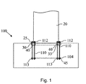
- Fig. 1 shows a sectional view of an embodiment of a concrete foundation 100 for the support of a structure 20, including a foundation interface 30.
- the foundation interface includes a prefabricated concrete element 33. It has a plurality of through holes 40, which are geometrically arranged to correspond to an arrangement of holes or through holes 25 of the structure 20 to be supported.
- Cast into concrete foundation 100 is also an anchor element 104, which may also include a plurality of elements, with a plurality of through holes 45.
- the anchor element is fastened to anchor bolts 110, typically via nuts 113, and portions of the bolts protrude from the surface of the foundation 100 in order to allow the mounting of the structure 20, typically via nuts 112.
- foundation interface 30 is provided. Portions of the anchor bolts 110 protrude through the through holes 40 of the foundation interface.
- the structure 20 is mounted on the foundation 100, more specifically on the foundation interface 30.
- the structure may be a wind turbine for on-shore use.
- Fig. 2 shows a perspective top view of a concrete foundation interface 30 according to an embodiment.
- the foundation interface (henceforth also called element) is formed as a ring and includes two concentric circles of through holes 40.
- the element should withstand high forces, typically it is made of steel reinforced concrete, fiber reinforced concrete, high-performance concrete or ultra-high-performance concrete. Also combinations thereof are suitable.
- the element is typically prefabricated, which means that it is cast in a workshop and not on the construction site for the foundation. However, also the production of the element at the construction site is possible and is regarded to fall under the scope of the present application.
- Fig. 3 shows a perspective side view of the embodiment shown in Fig. 2 .
- the foundation interface typically has a shape which substantially resembles the shape of a flange of the structure to be supported. Typical shapes are selected from the group consisting of a rectangular plate, a circular plate, a ring, a rectangular plate with a recess, and an oval plate. Figs 2 and 3 show, as a non-limiting example, an embodiment with the shape of a ring.
- the foundation interface is provided with a plurality of through holes. The diameter of the holes is typically uniform amongst the holes and resembles the diameter of the anchor bolts with which the structure to be supported is fastened to the foundation.
- a typical diameter of the holes is from 20 mm to 300 mm, more typically from 40 mm to 200 mm, its value, together with the number of holes, is strongly dependent on the weight and height of the structure to be supported, and what forces are exerted on the structure, e.g. wind forces in case of a wind turbine.
- Methods to calculate the necessary strength and diameter of the bolts, as well as any other calculations necessary for the dimensioning of parameters of methods and apparatuses described herein, are well known to a skilled person.
- the concrete foundation interface has the shape of a ring with, exemplarily, a rectangular cross section.
- the cross section may also have a variety of other shapes, e.g. a half circle, a polygon, a combination thereof, or the like, provided that one face is substantially plane in order to facilitate mounting of the structure to be supported.
- the inner diameter of the ring depends mainly on the dimensions of the structure to be supported, as the through holes 40 in the ring serve as an accommodation for bolts with which the supported structure is fixated to the foundation. In a non-limiting embodiment used for foundations for wind turbines, the inner diameter of the ring is from 2 m to 10 m, more typically from 3 m to 8 m.
- the width of the ring is typically from 20 cm to 100 cm, more typically from 30 cm to 60 cm.
- the number of through holes may vary from 4 to 300, more typically from 10 to 200, depending on the dimensions and type of the supported structure.
- the through holes 40 are typically, but not necessarily, evenly distributed in a circumferential direction.
- the holes are provided in two concentric circles, which allows e.g. for the fixation of the structure on its inner side and outer side, as is shown schematically in Fig. 1 .
- Fig. 4 shows an embodiment of the foundation interface 30, which includes a number of prefabricated segments 35.
- the interface includes four ring segments 35. They each include at least one connection element 45. Fixed together, they form the foundation interface.
- the connection elements 45 may comprise concrete or, typically, steel. Suitable ways of designing and implementing the connection elements are well known to a skilled person, they are only shown schematically.
- the connection of the segments 35 to each other may for example be provided by bolts or by a tongue-and-groove type connection. A plurality of segments may be transported more easily in comparison to a one-piece-structure as shown in Fig. 2 .
- Fig. 5 shows an embodiment of the foundation interface including at least one groove 50 on the surface on which the supported structure is to be mounted.
- This groove is connected by one or more channels or ducts 60 in the foundation interface (dotted lines) to openings 55 in a face of the interface.
- the openings may be provided in the face facing the structure to be mounted, or a side face of the foundation interface. In the latter case it should be ensured that the openings are still accessible after casting of the foundation.
- the groove may have a depth from 0.5 cm to 20 cm, more typically from 1 cm to 8 cm, and a width from 0,5 to 20 cm, more typically from 1 cm to 8 cm.
- the ducts or channels 60 may have a diameter from 1.0 cm to 20 cm, more typically from 1.5 cm to 8 cm.
- the dimensioning of the groove, the ducts and the opening mainly depends on the size of the structure to be supported.
- the groove, ducts and openings are typically all from 1.0 cm to 3.0 cm wide.
- the ripple of the foundation interface measured over a distance of 1 m, may typically be about 1 mm to 4 mm. Thus, there may remain a small gap between the interface and the steel structure of up to a few mm.
- the groove may be filled with a suitable substance after the structure is mounted.
- suitable substance e.g. a concrete suspension, or a synthetic material, e.g. a resin or a thermoplastic.
- the substance is injected via openings 55 and ducts 60 into groove 50 and evenly distributes under the injection pressure over the entire length of the groove.
- the filler protrudes over the edge of the groove and starts to fill the gap to the structure. After the filler has set, the gap is hermetically sealed, improving e.g. load bearing capacity, corrosion resistance and water tightness of the structure-foundation combination.
- the embodiments shown in Figs. 1 , 2 , 3 , 4 and 5 may for example be used in a foundation of a wind turbine 500, which is schematically depicted in Fig. 6 .
- the wind turbine includes a tower 20, a nacelle 22, a hub 26, two or more rotor blades 28, and a foundation 100.
- the tower is mounted to the concrete foundation 100, which includes bolts 110, an anchor element 104, and a foundation interface 30, which are all cast in the concrete foundation.
- the foundation may be used for any other structure which typically requires a concrete foundation, e.g. ski lifts, towers for broadcasting purposes, traffic signs, and the like.
- a method of mounting a foundation including a foundation interface is described in the following with respect to Fig. 7 to Fig. 10 .
- This is only a non-limiting example and is not intended to be necessarily executed in the described order of the different work blocks.
- modifications of the described procedure or apparatuses may be suitable, which includes also performing work blocks in a different order. Those modifications are also regarded to fall into the scope of the present application.
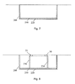
- Fig. 7 shows a building pit 200, which is excavated at the site where the structure shall be erected.
- the pit is typically round or has a square shape, and a flat bottom, the dimensions depend on the size and type of the structure.
- the pit is then equipped with a formwork 220.
- a layer of blinding concrete with a thickness from 2 cm to 20 cm is cast, more typically from 3 cm to 12 cm.
- the formwork may e.g. also be erected on the ground without excavating a pit.
- FIG. 8 shows the preparation for the erection of the anchor bolt system of the foundation.
- a support structure 230 which typically includes steel or concrete, is put into the formwork 220 and rests on the layer of blinding concrete 210.
- the support structure may be chosen amongst a variety of variations. E.g., welded steel columns and/or T-bars may be used, or concrete elements, or individually fabricated structures, or combinations thereof. The only requirement is, that the structure must be able to stably stand on the blinding layer without support, and that it can bear the weight of the anchor bolt system and the foundation interface. Implementing such a support structure is within the standard knowledge of a skilled person.
- foundation interface 30 is placed on the support structure 230.
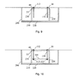
- Fig. 9 shows that anchor bolts 110 are placed in the through holes 40 of the foundation interface 30.
- the bolts are tightened with nuts 112, so that they are fixed in the appropriate position, protruding with a portion out of the foundation interface 30. Nuts 112 are later removed before mounting the structure.
- Fig. 10 shows anchor element 104 mounted to the bolts 110 and its fixation with nuts 113.
- an anchor ring 104 is used.
- concrete is filled into the pit up to a level such that the upper face of the foundation interface is substantially flush with the surrounding concrete.
- the concrete is left to set.
- the bolts 112 are removed, and the foundation is ready to be used to mount a structure to the parts of the bolts 110 protruding from the surface of foundation interface 30.
- the system of anchor bolts 110, foundation interface 30, anchor elements or anchor ring 104, and nuts 112, 113 may in another embodiment also be mounted outside pit 200 and then be placed in the formwork onto support 230.
Landscapes
- Engineering & Computer Science (AREA)
- Life Sciences & Earth Sciences (AREA)
- General Engineering & Computer Science (AREA)
- Mining & Mineral Resources (AREA)
- Paleontology (AREA)
- Civil Engineering (AREA)
- General Life Sciences & Earth Sciences (AREA)
- Structural Engineering (AREA)
- Sustainable Development (AREA)
- Sustainable Energy (AREA)
- Chemical & Material Sciences (AREA)
- Combustion & Propulsion (AREA)
- Mechanical Engineering (AREA)
- Foundations (AREA)
- Wind Motors (AREA)
Applications Claiming Priority (1)
| Application Number | Priority Date | Filing Date | Title |
|---|---|---|---|
| US12/770,832 US20110131899A1 (en) | 2010-04-30 | 2010-04-30 | Apparatus and method for producing a concrete foundation |
Publications (1)
| Publication Number | Publication Date |
|---|---|
| EP2383393A1 true EP2383393A1 (fr) | 2011-11-02 |
Family
ID=44080594
Family Applications (1)
| Application Number | Title | Priority Date | Filing Date |
|---|---|---|---|
| EP11163976A Withdrawn EP2383393A1 (fr) | 2010-04-30 | 2011-04-27 | Appareil et procédé pour produire une fondation en béton |
Country Status (7)
| Country | Link |
|---|---|
| US (1) | US20110131899A1 (fr) |
| EP (1) | EP2383393A1 (fr) |
| JP (1) | JP2011236731A (fr) |
| KR (1) | KR20110121567A (fr) |
| CN (1) | CN102277877A (fr) |
| AU (1) | AU2011201780A1 (fr) |
| CA (1) | CA2737499A1 (fr) |
Cited By (3)
| Publication number | Priority date | Publication date | Assignee | Title |
|---|---|---|---|---|
| DE102013221432A1 (de) * | 2013-10-22 | 2015-04-23 | Wobben Properties Gmbh | Windenergieanlage und Windenergieanlagen-Fundament |
| CN105155571A (zh) * | 2015-08-20 | 2015-12-16 | 江苏金海新能源科技有限公司 | 可更换的预应力锚栓装置及其安装和更换施工方法 |
| CN113653199A (zh) * | 2021-08-30 | 2021-11-16 | 中冶建工集团有限公司 | 一种预埋加劲锚板地脚螺栓的施工方法 |
Families Citing this family (30)
| Publication number | Priority date | Publication date | Assignee | Title |
|---|---|---|---|---|
| US8146323B1 (en) * | 2010-05-10 | 2012-04-03 | Tooman Norman L | Apparatus and method for installing anchor bolts in a cylindrical pier foundation |
| DE102010039796A1 (de) * | 2010-06-14 | 2011-12-15 | Max Bögl Bauunternehmung GmbH & Co. KG | Turm mit einem Adapterstück sowie Verfahren zur Herstellung eines Turms mit einem Adapterstück |
| CN102095052B (zh) * | 2010-11-25 | 2013-06-12 | 华锐风电科技(集团)股份有限公司 | 地脚螺栓锚固系统的安装方法及安装工业设备的方法 |
| US8555518B2 (en) * | 2011-05-18 | 2013-10-15 | Norman Tooman | Grout template for wind turbine foundations |
| WO2013040495A1 (fr) | 2011-09-16 | 2013-03-21 | Goss Construction, Inc. | Systèmes et procédés de coffrage |
| ES2405034B1 (es) * | 2011-11-17 | 2014-04-15 | Acciona Windpower, S.A. | Procedimiento y unidad para la fijación de una torre de un aerogenerador a una cimentación y aerogenerador que incorpora dicha unidad |
| CN102704505A (zh) * | 2012-06-11 | 2012-10-03 | 天津大学 | 一种陆上风电机组地基基础 |
| US10100548B2 (en) * | 2012-10-01 | 2018-10-16 | Valmont Industries, Inc. | Base angle attachment assemblies |
| CN102900095B (zh) * | 2012-10-11 | 2015-03-04 | 甘肃省电力公司电力经济技术研究院 | 输电杆塔板式单索基础结构 |
| CN102900094B (zh) * | 2012-10-11 | 2015-02-04 | 甘肃省电力公司电力经济技术研究院 | 输电杆塔板式三索基础结构 |
| AT513261B1 (de) * | 2012-10-30 | 2014-03-15 | Univ Wien Tech | Verfahren zur Herstellung eines Turmbauwerks aus Stahlbeton |
| CN103046795B (zh) * | 2013-01-09 | 2015-04-15 | 莱芜钢铁集团有限公司 | 一种线杆或灯杆万能安装底座 |
| DE102013211750A1 (de) * | 2013-06-21 | 2014-12-24 | Wobben Properties Gmbh | Windenergieanlage und Windenergieanlagen-Fundament |
| ES2589962B1 (es) * | 2015-04-17 | 2017-09-08 | Gamesa Innovation & Technology, S.L. | Dispositivo de unión de un tramo metálico con un tramo de hormigón en una torre hueca híbrida |
| JP6570412B2 (ja) * | 2015-10-13 | 2019-09-04 | 東急建設株式会社 | アンカーボルト構造体 |
| KR101888231B1 (ko) * | 2015-12-21 | 2018-09-06 | 고려대학교 산학협력단 | 수직도 오차 보정이 가능한 콘크리트 기초-타워 연결구조 |
| US11236727B2 (en) * | 2015-12-21 | 2022-02-01 | Vestas Wind Systems A/S | Method for forming a wind turbine foundation and related system for forming such a foundation |
| CA2916228C (fr) * | 2015-12-23 | 2019-02-26 | 649119 N.B. Inc. | Fondation de beton prefabriquee d'une construction modulaire destinee a une tour de telecommunication ou une tour d'eolienne |
| DE102016203526A1 (de) * | 2016-01-20 | 2017-07-20 | Ventur GmbH | Adaptervorrichtung für einen Turm und Verfahren zur Herstellung |
| DK3312416T3 (da) * | 2016-10-24 | 2022-07-25 | Nordex Energy Spain S A | Vindmølletårn på fundament |
| WO2018086022A1 (fr) * | 2016-11-10 | 2018-05-17 | General Electric Company | Procédés et appareil de remise en état de fondations d'éolienne |
| CN109653520A (zh) * | 2019-01-07 | 2019-04-19 | 龙信建设集团有限公司 | 预制装配混凝土结构外墙底部企口防护装置及其安装方法 |
| US10822764B2 (en) | 2019-02-21 | 2020-11-03 | General Electric Company | Method of connecting a tower to a foundation |
| WO2020249852A1 (fr) * | 2019-06-14 | 2020-12-17 | Peikko Group Oy | Procédé de montage d'un élément de construction préfabriqué sur un autre élément de construction et agencement de liaison |
| CN110925145B (zh) * | 2019-12-16 | 2020-11-03 | 徐州天启新材料科技有限公司 | 一种发电设备用防护装置 |
| CN111379669A (zh) * | 2020-03-24 | 2020-07-07 | 国电联合动力技术有限公司 | 一种风机基础混凝土台柱的加固装置及加固方法 |
| CN112302881B (zh) * | 2020-09-15 | 2024-06-25 | 重庆大学 | 一种用于钢-混塔筒的预制混凝土管片连接构造 |
| CN112982471A (zh) * | 2021-02-26 | 2021-06-18 | 中国能源建设集团江苏省电力设计院有限公司 | 一种跨越塔与基础的连接节点及其施工方法 |
| CN114000655B (zh) * | 2021-11-03 | 2023-03-03 | 江苏城归设计有限公司 | 钢管混凝土柱组合柱脚结构 |
| CN114411798B (zh) * | 2021-12-24 | 2023-08-25 | 重庆市科源能源技术发展有限公司 | 一种风机基础结构 |
Citations (5)
| Publication number | Priority date | Publication date | Assignee | Title |
|---|---|---|---|---|
| NL8004538A (nl) * | 1980-08-11 | 1982-03-01 | Siemen Spinder Handelende Onde | Werkwijze voor het plaatsen van een betonvoet, aldus vervaardigde betonvoetfundatie alsmede betonelementen ten gebruike daarvoor. |
| FR2692611A1 (fr) * | 1992-06-17 | 1993-12-24 | Prefatlantique | Platine de fixation pour pylône. |
| DE102005044989B3 (de) * | 2005-09-21 | 2006-12-14 | Nordex Energy Gmbh | Verfahren zur Gründung eines Fundamentkörpers für eine Windenenergieanlage |
| DE102007060379A1 (de) * | 2007-12-12 | 2009-06-25 | Repower Systems Ag | Verankerung eines Turms einer Windenergieanlage |
| WO2009103475A2 (fr) * | 2008-02-22 | 2009-08-27 | Repower Systems Ag | Érection d'une éolienne |
Family Cites Families (13)
| Publication number | Priority date | Publication date | Assignee | Title |
|---|---|---|---|---|
| US4104885A (en) * | 1976-06-21 | 1978-08-08 | Fairclough Construction Group Limited | Tunnel lining |
| US5505033A (en) * | 1988-12-06 | 1996-04-09 | 501 Hitachi Metals Ltd. | Column base structure and connection arrangement |
| US5586417A (en) * | 1994-11-23 | 1996-12-24 | Henderson; Allan P. | Tensionless pier foundation |
| IL134724A0 (en) * | 2000-02-24 | 2001-04-30 | Giltek Telecomm Ltd | Foundation for a tower and a method for its deployment on site |
| DE10226996B4 (de) * | 2001-10-09 | 2014-07-03 | Aloys Wobben | Verfahren zur Erstellung eines Fundaments, insbesondere für einen Turm einer Windenergieanlage |
| US7533505B2 (en) * | 2003-01-06 | 2009-05-19 | Henderson Allan P | Pile anchor foundation |
| DE102004017006B4 (de) * | 2004-04-02 | 2012-03-29 | Aloys Wobben | Verfahren zum Errichten eines Turmes |
| DE102004017008B4 (de) * | 2004-04-02 | 2009-10-22 | Aloys Wobben | Verfahren zum Errichten eines Turmes |
| US8051627B2 (en) * | 2006-04-30 | 2011-11-08 | General Electric Company | Tower adapter, method of producing a tower foundation and tower foundation |
| CN101484643B (zh) * | 2006-07-05 | 2011-02-02 | 维斯塔斯风力系统有限公司 | 塔架建筑 |
| EP2199469B1 (fr) * | 2008-12-16 | 2012-06-06 | Vestas Wind Systems A/S | Fondation pour permettre l'ancrage d'une tour d'éolienne à l'aide de boulons traversants remplaçables |
| US8272181B2 (en) * | 2009-03-03 | 2012-09-25 | Tooman Norman L | Grout sleeve for foundation anchor bolts and method for protection of anchor bolts for a vertical structure, including wind turbines |
| US20110138706A1 (en) * | 2010-08-13 | 2011-06-16 | Stefan Voss | Wind turbine anchor element |
-
2010
- 2010-04-30 US US12/770,832 patent/US20110131899A1/en not_active Abandoned
-
2011
- 2011-04-14 CA CA2737499A patent/CA2737499A1/fr not_active Abandoned
- 2011-04-19 AU AU2011201780A patent/AU2011201780A1/en not_active Abandoned
- 2011-04-27 JP JP2011098838A patent/JP2011236731A/ja not_active Withdrawn
- 2011-04-27 EP EP11163976A patent/EP2383393A1/fr not_active Withdrawn
- 2011-04-28 CN CN2011101181725A patent/CN102277877A/zh active Pending
- 2011-04-28 KR KR1020110040106A patent/KR20110121567A/ko not_active Withdrawn
Patent Citations (5)
| Publication number | Priority date | Publication date | Assignee | Title |
|---|---|---|---|---|
| NL8004538A (nl) * | 1980-08-11 | 1982-03-01 | Siemen Spinder Handelende Onde | Werkwijze voor het plaatsen van een betonvoet, aldus vervaardigde betonvoetfundatie alsmede betonelementen ten gebruike daarvoor. |
| FR2692611A1 (fr) * | 1992-06-17 | 1993-12-24 | Prefatlantique | Platine de fixation pour pylône. |
| DE102005044989B3 (de) * | 2005-09-21 | 2006-12-14 | Nordex Energy Gmbh | Verfahren zur Gründung eines Fundamentkörpers für eine Windenenergieanlage |
| DE102007060379A1 (de) * | 2007-12-12 | 2009-06-25 | Repower Systems Ag | Verankerung eines Turms einer Windenergieanlage |
| WO2009103475A2 (fr) * | 2008-02-22 | 2009-08-27 | Repower Systems Ag | Érection d'une éolienne |
Cited By (3)
| Publication number | Priority date | Publication date | Assignee | Title |
|---|---|---|---|---|
| DE102013221432A1 (de) * | 2013-10-22 | 2015-04-23 | Wobben Properties Gmbh | Windenergieanlage und Windenergieanlagen-Fundament |
| CN105155571A (zh) * | 2015-08-20 | 2015-12-16 | 江苏金海新能源科技有限公司 | 可更换的预应力锚栓装置及其安装和更换施工方法 |
| CN113653199A (zh) * | 2021-08-30 | 2021-11-16 | 中冶建工集团有限公司 | 一种预埋加劲锚板地脚螺栓的施工方法 |
Also Published As
| Publication number | Publication date |
|---|---|
| AU2011201780A1 (en) | 2011-11-17 |
| CN102277877A (zh) | 2011-12-14 |
| CA2737499A1 (fr) | 2011-10-30 |
| US20110131899A1 (en) | 2011-06-09 |
| JP2011236731A (ja) | 2011-11-24 |
| KR20110121567A (ko) | 2011-11-07 |
Similar Documents
| Publication | Publication Date | Title |
|---|---|---|
| US20110131899A1 (en) | Apparatus and method for producing a concrete foundation | |
| CN108603492B (zh) | 利用分段支承板的塔架区段和方法 | |
| EP2256338B1 (fr) | Fondation particulièrement pour une éolienne et éolienne | |
| US9322396B2 (en) | Foundation for a wind turbine | |
| US8443557B2 (en) | Tower base section of a wind turbine, a wind turbine and a system for mounting a tower | |
| AU2011267375B2 (en) | Tower comprising an adapter piece and method for producing a tower comprising an adapter piece | |
| CA2524931C (fr) | Fondations pour installation d'energie eolienne | |
| CN108474193B (zh) | 一种形成风轮机基座的方法及用于形成此基座的相关系统 | |
| DK1735506T3 (en) | Method of erecting a tower | |
| US20120023860A1 (en) | Adapter Configuration for a Wind Tower Lattice Structure | |
| KR20110004797A (ko) | 윈드 터빈 스페이스 프레임 타워용의 모듈형 지상 기초부 | |
| EP2981654B1 (fr) | Ensemble tour pour une structure de tour | |
| EP2550405B1 (fr) | Procédé permettant de construire une fondation | |
| CN105339654A (zh) | 风能设施基座 | |
| KR20140051531A (ko) | 해양 지지구조물과 그 제조방법 및 시공방법 | |
| JP2022518271A (ja) | オフショア設備用の重力式基礎を製造するための方法および重力式基礎 | |
| GB2508870A (en) | Circular tapered levelling shims for structures | |
| KR20150076789A (ko) | 해상 풍력발전 중간구조물 및 이를 구비한 해상 풍력발전 구조물 | |
| RU2782015C2 (ru) | Фундамент для ветроэнергетической установки | |
| NZ624309B2 (en) | Foundation for a wind turbine |
Legal Events
| Date | Code | Title | Description |
|---|---|---|---|
| AK | Designated contracting states |
Kind code of ref document: A1 Designated state(s): AL AT BE BG CH CY CZ DE DK EE ES FI FR GB GR HR HU IE IS IT LI LT LU LV MC MK MT NL NO PL PT RO RS SE SI SK SM TR |
|
| AX | Request for extension of the european patent |
Extension state: BA ME |
|
| PUAI | Public reference made under article 153(3) epc to a published international application that has entered the european phase |
Free format text: ORIGINAL CODE: 0009012 |
|
| STAA | Information on the status of an ep patent application or granted ep patent |
Free format text: STATUS: THE APPLICATION IS DEEMED TO BE WITHDRAWN |
|
| 18D | Application deemed to be withdrawn |
Effective date: 20120503 |