EP2383396A1 - Bague pour robinet - Google Patents
Bague pour robinet Download PDFInfo
- Publication number
- EP2383396A1 EP2383396A1 EP09804500A EP09804500A EP2383396A1 EP 2383396 A1 EP2383396 A1 EP 2383396A1 EP 09804500 A EP09804500 A EP 09804500A EP 09804500 A EP09804500 A EP 09804500A EP 2383396 A1 EP2383396 A1 EP 2383396A1
- Authority
- EP
- European Patent Office
- Prior art keywords
- current
- valve core
- tap valve
- core according
- shell
- Prior art date
- Legal status (The legal status is an assumption and is not a legal conclusion. Google has not performed a legal analysis and makes no representation as to the accuracy of the status listed.)
- Granted
Links
Images
Classifications
-
- E—FIXED CONSTRUCTIONS
- E03—WATER SUPPLY; SEWERAGE
- E03C—DOMESTIC PLUMBING INSTALLATIONS FOR FRESH WATER OR WASTE WATER; SINKS
- E03C1/00—Domestic plumbing installations for fresh water or waste water; Sinks
- E03C1/02—Plumbing installations for fresh water
- E03C1/08—Jet regulators or jet guides, e.g. anti-splash devices
-
- B—PERFORMING OPERATIONS; TRANSPORTING
- B05—SPRAYING OR ATOMISING IN GENERAL; APPLYING FLUENT MATERIALS TO SURFACES, IN GENERAL
- B05B—SPRAYING APPARATUS; ATOMISING APPARATUS; NOZZLES
- B05B1/00—Nozzles, spray heads or other outlets, with or without auxiliary devices such as valves, heating means
- B05B1/30—Nozzles, spray heads or other outlets, with or without auxiliary devices such as valves, heating means designed to control volume of flow, e.g. with adjustable passages
- B05B1/3006—Nozzles, spray heads or other outlets, with or without auxiliary devices such as valves, heating means designed to control volume of flow, e.g. with adjustable passages the controlling element being actuated by the pressure of the fluid to be sprayed
-
- B—PERFORMING OPERATIONS; TRANSPORTING
- B05—SPRAYING OR ATOMISING IN GENERAL; APPLYING FLUENT MATERIALS TO SURFACES, IN GENERAL
- B05B—SPRAYING APPARATUS; ATOMISING APPARATUS; NOZZLES
- B05B1/00—Nozzles, spray heads or other outlets, with or without auxiliary devices such as valves, heating means
- B05B1/26—Nozzles, spray heads or other outlets, with or without auxiliary devices such as valves, heating means with means for mechanically breaking-up or deflecting the jet after discharge, e.g. with fixed deflectors; Breaking-up the discharged liquid or other fluent material by impinging jets
- B05B1/262—Nozzles, spray heads or other outlets, with or without auxiliary devices such as valves, heating means with means for mechanically breaking-up or deflecting the jet after discharge, e.g. with fixed deflectors; Breaking-up the discharged liquid or other fluent material by impinging jets with fixed deflectors
- B05B1/265—Nozzles, spray heads or other outlets, with or without auxiliary devices such as valves, heating means with means for mechanically breaking-up or deflecting the jet after discharge, e.g. with fixed deflectors; Breaking-up the discharged liquid or other fluent material by impinging jets with fixed deflectors the liquid or other fluent material being symmetrically deflected about the axis of the nozzle
-
- B—PERFORMING OPERATIONS; TRANSPORTING
- B05—SPRAYING OR ATOMISING IN GENERAL; APPLYING FLUENT MATERIALS TO SURFACES, IN GENERAL
- B05B—SPRAYING APPARATUS; ATOMISING APPARATUS; NOZZLES
- B05B1/00—Nozzles, spray heads or other outlets, with or without auxiliary devices such as valves, heating means
- B05B1/34—Nozzles, spray heads or other outlets, with or without auxiliary devices such as valves, heating means designed to influence the nature of flow of the liquid or other fluent material, e.g. to produce swirl
-
- E—FIXED CONSTRUCTIONS
- E03—WATER SUPPLY; SEWERAGE
- E03C—DOMESTIC PLUMBING INSTALLATIONS FOR FRESH WATER OR WASTE WATER; SINKS
- E03C1/00—Domestic plumbing installations for fresh water or waste water; Sinks
- E03C1/02—Plumbing installations for fresh water
- E03C2001/026—Plumbing installations for fresh water with flow restricting devices
Definitions
- the present invention relates to a bathroom tap, in particular to a tap valve core arranged at the outlet of a tap, or the outlets of piston-free delayed valves of some underslung feeler levers and central outlets of some showers.
- water nozzle bubbling heads widely used are generally filter screen nozzle bushings assembled in shells of different bubblers, ventilation channels are arranged around the filter screen nozzle bushings, current passes through a porous dense screen, is sprinkled and mixed in the air to generate bubbles, and then passes through a multi-layer enclosed filter screen arranged at the water outlet to generate slow and gentle water discharge.
- Some tap outlets directly employ fine holes similar to shower heads to divide current into trickles, allowing current to flow slowly.
- the water nozzle bubbling heads have the disadvantages of easily causing blockage due to impurities after long-term use especially obvious for poor water quality environment and bigger impact force of water flow, easily causing splash, being unfavorable for scientifically saving water visually due to traditional and monotonous outflow shape, and having high cost and limited compatibility as some taps are molded in big discs or flat nozzles to focus on the waterfall.
- a technical problem to be solved by the invention is to provide a tap valve core capable of preventing water splash.
- the technical solution of the invention employed to solve the technical problem is a tap valve core comprising a shell and a current unblocking opening arranged in the shell, and being characterized in that a limit stop with shape and size adapting to the current unblocking opening is arranged below the current unblocking opening, and a gap is arranged between the upper surface of the limit stop and an outlet of the current unblocking opening.
- a connecting structure is arranged between the limit stop and the shell, and the limit stop is connected to the shell by the connecting structure.
- the connecting structure comprises a support bar fixedly arranged at the upper surface of the limit stop and a current guide support arranged at the support bar and having through holes, the support bar passes through the current unblocking opening, and the current guide support is arranged above the current unblocking opening.
- the current guide support takes a concave shape, the concave part thereof forms a current dividing chamber, and the through holes are arranged at side wall of the current dividing chamber. Furthermore, a rectifying cover is fixedly arranged at the top of the current dividing chamber, and a rectifying through hole is arranged at the middle part of the rectifying cover.
- the support bar is in threaded connection to the current guide support, and axis of the support bar coincides with that of the through holes.
- a threaded through hole is arranged inside the support bar and the limit stop, a screw is arranged inside the threaded through hole, and axis of the screw coincides with that of the rectifying through hole.
- the rectifying cover is made of a flexible material, and a spring is arranged between the current guide support and the rectifying cover.
- the rectifying cover is made of an elastic element.
- a pressure relief chamber is arranged at the current guide support, a pressure relief channel interface is arranged on the current guide support at the top of the pressure relief chamber, and a pressure relief water outlet is arranged on the current guide support at the bottom of the pressure relief chamber; a sealing baffle covering the pressure relief water outlet is arranged at the top of the support bar, and a return spring is arranged between the upper surface of the sealing baffle and the current guide support.
- an underslung feeler lever is fixedly arranged at the lower end of the limit stop, and a sealing ring is fixedly arranged at the current guide support below the sealing baffle.
- At least a pinhole is arranged inside the limit stop and the support bar.
- a filter screen covering the top of the pinhole or a pin penetrating the pinhole is arranged at the current guide support. Furthermore, the filter screen is arranged between the current guide support and the current unblocking opening.
- diameter of the pinhole arranged in the support bar is greater than that of the pinhole arranged in the limit stop, and a lighting device is arranged in the pinhole with greater diameter.
- a flat ring is arranged at the outlet at the lower part of the shell, and the current unblocking opening is arranged at the flat ring.
- the current unblocking opening is arranged at the middle part of the flat ring. Furthermore, a bushing is fixedly connected to the inner wall of the shell, the flat ring is the bottom of the bushing, and the current guide support is arranged at the top of the bushing.
- the flat ring and the shell are integral.
- a step is arranged at the upper inner wall of the shell, and the current guide support is supported at the step.
- the external surface of the shell is smooth.
- a one-way locking structure is arranged at the inner wall of the shell below the flat ring.
- the shell is a hollow frustum cone.
- the middle part of the external surface of the shell is concave inwards.
- the beneficial effects of the invention are as follows: a film-like hollow waterfall curtain with beautiful appearance and large visual flow forms due to even resistance overflow of current on the upper surface of the limit stop in operation, thus scientifically saving water resources.
- the falling film-like water curtain has smaller energy, allowing the impact force to be small, and bringing comfortable, natural and gentle feeling in water use.
- the tap valve core is more suitable for wide application to various taps due to low cost.
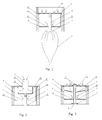
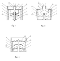
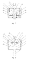
- Marks in the figures are as follows: busing 1, current unblocking opening 2, limit stop 3, shell 4, current guide support 5, rectifying through hole 6, filter screen 7, pinhole 8, rectifying cover 9, lighting device 10, hollow waterfall curtain 11, current dividing chamber 12, flat ring 13, support bar 14, through holes 15, screw 16, sealing baffle 17, spring 18, return spring 19, underslung feeler lever 20, pressure relief channel interface 21, sealing ring 22, pressure relief chamber 23, pressure relief water outlet 24 and one-way locking structure 25.
- the direction of arrow in the figures is the direction of flow.
- the tap valve core of the invention comprises a shell 4 and a current unblocking opening 2 arranged in the shell 4, and is characterized in that a limit stop 3 with shape and size adapting to the current unblocking opening 2 is arranged below the current unblocking opening 2, and a gap is arranged between the upper surface of the limit stop 3 and an outlet of the current unblocking opening 2.
- the tap is turned on in operation, then the whole current falls from the current unblocking opening 2, is evenly blocked by a water blocking surface (upper surface) of the limit stop 3 below the current unblocking opening 2, and naturally overflows towards the periphery of the limit stop 3, forming a small-to-big thin hollow waterfall curtain 11, the hollow waterfall curtain 11 formed gradually flows together and falls by the surface tension of water, which equals that tiny bubbles from screen nozzle bubblers at traditional water outlets are expanded by tens of thousands of times, presenting a reverse drop-shaped hollow waterfall water cover or large ellipsoidal hollow waterfall bubble with beautiful appearance and large visual flow, satisfying psychological needs of users and scientifically saving water resources.
- the blocking and buffer action of the upper surface of the limit stop 3 causes partial energy loss of current, thus the falling hollow waterfall curtain 11 formed has small energy, allowing the impact force to be small, bringing natural and comfortable feeling in water use and preventing water splash.
- the current unblocking opening 2 can be arranged as a bigger channel to prevent impurities in the current from blocking the current unblocking opening 2.
- the form of the limit stop 3 with shape and size adapting to the current unblocking opening 2 can be that the area of the limit stop 3 is slightly larger, equal to or slightly smaller than that of the current unblocking opening 2 to facilitate the formation of the hollow waterfall curtain 11; and the current unblocking opening 2 can be arranged into circle, rectangle and even irregular shapes, and the shape of the limit stop 3 shall correspond to that of the current unblocking opening 2.
- a support can be fixedly arranged outside pipe body of the tap, the support extends below the current unblocking opening 2 to connect the limit stop 3 to a support right below the current unblocking opening 2, as a preferred embodiment, a connecting structure is arranged between the limit stop 3 and the shell 4, and the limit stop 3 is connected to the shell 4 by the connecting structure. If multiple tiny reinforced bars can be used to form an inverted umbrella structure, one end of the inverted umbrella structure is connected with the shell 4, and the other end is connected with the limit stop 3, however, in the embodiment, the multiple tiny reinforced bars will interfere with the current after the current flows out of the current unblocking opening 2, which is unfavorable for the formation of the hollow waterfall curtain.
- the connecting structure comprises a support bar 14 fixedly arranged at the upper surface of the limit stop 3 and a current guide support 5 arranged at the support bar 14 and having through holes 15, and the support bar 14 passes through the current unblocking opening 2, and the current guide support 5 is arranged above the current unblocking opening 2. Then the current flows out of the current unblocking opening 2, flows to the upper surface of the limit stop 3 along the external surface of the support bar 14 without any blockage, thus facilitating the formation of the hollow waterfall curtain 11, and perfectly preventing water splash.
- the current guide support 5 takes a concave shape, the concave part thereof forms a current dividing chamber 12, and the through holes 15 are arranged at side wall of the current dividing chamber 12.
- the current from the tap flows into the current dividing chamber 12, flows into a water chamber between the current guide support 5 and the current unblocking opening 2 from the through holes 15 on the side wall of the current dividing chamber 12, and then flows out of the current unblocking opening 2.
- the arrangement of the current dividing chamber 12 can help rectify intricate current, thus facilitating the formation of the hollow waterfall curtain 11.
- a rectifying cover 9 is fixedly arranged at the top of the current dividing chamber 12, and a rectifying through hole 6 is arranged at the middle part of the rectifying cover 9. Then water from the tap flows into the current dividing chamber 12 through the rectifying through hole 6, thus improving the rectifying effect in a better manner, preventing unilateral impact on the inner wall of the shell 4 resulting from different water outlet angles of some taps or alternative structural styles, and affecting the shape of the hollow waterfall curtain 11.
- the structure of the embodiment is as shown in Figure 2 .
- the support bar 14 can be directly clamped on the current guide support 5 (as shown in Figure 1 ); or the support bar 14 and the current guide support 5 are subject to an integrated structure, the area of the limit stop 3 shall be slightly smaller than that of the current unblocking opening when the support bar 14 and the current guide support 5 are integrated so as to penetrate the limit stop 3 through the lower part of the current unblocking opening 2 from the upper part thereof.
- the support bar 14 is in threaded connection to the current guide support 5, and axis of the support bar 14 coincides with that of the rectifying through hole 6.
- the matching distance between the current unblocking opening 2 and the limit stop 3 is regulated by screwing the support bar 14 in or out of the current guide support 5, thus changing the shape and size of the hollow waterfall curtain 11.
- water flow in the tap can be regulated by screwing in or out the support bar 14, thus saving water resources.
- a threaded through hole is arranged inside the support bar 14 and the limit stop 3
- a screw 16 is arranged inside the threaded through hole, and axis of the screw 16 coincides with that of the rectifying through hole 6, thus facilitating regulation of water flow from the outside of the water outlet, leaving out triangular valves for inflow regulation, adapting to configuration of ordinary taps, and reasonably utilizing water resources.
- the rectifying cover 9 is made of a flexible material, and a spring 18 is arranged between the current guide support 5 and the rectifying cover 9.
- the structure thereof is as shown in Figure 7 , when water pressure is higher, the flexible rectifying cover 9 resists elastic force of the spring 18 and moves downwards, that is, narrowing the clearance between the rectifying through hole 6 and the top end of the screw 16, thus correspondingly restricting outflow; on the contrary, when water pressure is low, the clearance between the rectifying through hole 6 and the top end of the screw 16 increases by the tension released by the spring 18, thus appropriately increasing outflow.
- proper amount of pinholes can be penetrated on the flexible rectifying cover 9 to compensate outflow.
- the flexible rectifying cover 9 can change the clearance between the rectifying through hole 6 and the top end of the screw 16 according to the change in water pressure, the outflow is automatically regulated when water pressure fluctuates, and the screw 16 is regulated through overall cooperation to keep the shape of the hollow waterfall curtain 11 more stable according to different water pressure of each floor.
- the rectifying cover 9 can be also made of an elastic element on the same principle. Even though the flexible rectifying cover 9 is replaced with an elastic rectifying cover 9, the same effect can be achieved.
- the spring 18 can be left out when the rectifying cover 9 is made of stainless steel spring leaf, plastic spring leaf, etc.
- a pressure relief chamber 23 is arranged at the current guide support 5
- a pressure relief channel interface 21 is arranged on the current guide support 5 at the top of the pressure relief chamber 23
- a pressure relief water outlet 24 is arranged on the current guide support 5 at the bottom of the pressure relief chamber 23
- a sealing baffle 17 covering the pressure relief water outlet 24 is arranged at the top of the support bar 14, and a return spring 19 is arranged between the upper surface of the sealing baffle 17 and the current guide support 5.
- the pressure relief channel interface 21 is in communication with a water chamber in the valve casing cover of publication No. CN1598380A , and the through holes 15 of the current guide support 5 are in communication with a rectangular water tank in a valve casing seat.
- the sealing baffle 17 resists elastic force of the return spring 19, causing water to fall from the pressure relief water outlet 24 of the current guide support 5, and when the return spring is lifted, the sealing baffle 17, the support bar 14 and the limit stop 3 return by the action of their own gravity and the return spring 19, automatically closing the pressure relief water outlet 24 of the current guide support 5, and completing pressure relief process.
- An underslung feeler lever 20 can be manually lifted or swung and the sealing baffle 17 can be lifted by fixedly arranging the underslung feeler lever 20 at a lower end of the limit stop 3; and a sealing ring 22 is fixedly arranged at the current guide support 5 below the sealing baffle 17, and can improve the tightness between the sealing baffle 17 and the pressure relief water outlet 24.
- a pinhole 8 is arranged inside the limit stop 3 and the support bar 14. Then a trickle or multiple trickles of water fall from the center of the hollow waterfall curtain 11 while forming the hollow waterfall curtain 11, thus being capable of increasing outflow aesthetics, and compensating for the deficiency that the central portion of the hollow waterfall has no water flow, and the water-saving anti-block and anti-splash waterfall tap valve core is more practical and improves the quality of life.
- a filter screen 7 covering the top of the pinhole 8 or a pin penetrating the pinhole 8 is arranged at the current guide support 5 to prevent blockage of the pinhole 8.
- the filter screen 7 is arranged between the current guide support 5 and the current unblocking opening 2.
- the filter screen 7 can unblock impurities in water besides being capable of further slowing the flow, prevent impurities from gathering by combining filtering with unblocking, and is favorable for the formation and stabilization of the hollow waterfall curtain 11.
- a small limit stop structure can be additionally arranged below the pinhole 8 of the limit stop 3 according to forming principle of the hollow waterfall curtain 11.
- the diameter of the pinhole 8 shall be increased to form multiple hollow waterfall curtains 11 with more than two layers, that is, small hollow waterfalls form in the hollow waterfall, which is unique, and available for landscape modeling.
- the lighting device 10 can be made of a lighting material or lighting tube such as a diode integrating red light and green light, conductors pass through a hollow column at the upper end of the pinhole 8, and are interlocked with corresponding power supply respectively such as small self-power generation device of tap water or micro switch. Then the hollow waterfall curtain 11 lights in red when hot water is turned on and in green when cold water is used, the flowing water curtain causes colors of light spectrum to be diverse, enriching the quality of life.
- a lighting material or lighting tube such as a diode integrating red light and green light
- the current unblocking opening 2 can be directly a water channel of an existing tap, water falls from an outlet of the tap to the upper surface of the limit stop 3, forming the hollow waterfall curtain 11, however, the outflow area of the hollow waterfall curtain 11 is larger, thus being unfavorable for water saving, as a preferred embodiment, a flat ring 13 is arranged at the outlet at the lower part of the shell 4, and the current unblocking opening 2 is arranged at the flat ring 13, which can save water resources obviously compared with the form of directly using the water channel of the existing tap as the current unblocking opening 2.
- the current unblocking opening 2 can be arranged at any position of the flat ring 13, as a preferred embodiment, the current unblocking opening 2 is arranged at the middle part of the flat ring 13, and can facilitate the arrangement of all components.
- a bushing 1 is fixedly connected to the inner wall of the shell 4, and the flat ring 13 is the bottom of the bushing 1. Meanwhile, a step forms between the top of the busing 1 and the inner wall of the shell 4, the current guide support 5 can be arranged at the top of the bushing 1 and welded at the step or directly laid at the step.
- the method is favorable for removal and replacement of all components.
- the structure is as shown in Figure 1, 2, 3 and 5 .
- the flat ring 13 and the shell 4 are integral, that is, the flat ring 13 and the shell 4 are integrated in molding, and even the current unblocking opening 2 is molded at the same time, or the flat ring 13 and the shell 4 are currently molded, and then the current unblocking opening 2 is drilled on the flat ring 13, and the method is characterized by being capable of reducing assembly links.
- the structure is as shown in Figure 4, 6 , 7 and 8 .
- the external surface of the shell 4 is smooth.
- the shell 4 can be shaped into a hollow frustum cone as shown in Figure 5 ; or the middle part of the external surface of the shell 4 is concave inwards as shown in Figure 6 , or even the shell 4 can be shaped into a hollow ellipsoid and an anti-removal surface of the art.
- flats or symmetrical notch steps for wrenches are arranged on external surfaces of most of existing bubbler head core structures, notch is left out at the external surface of the shell 4 in the invention, causing the appearance more aesthetic.
- the assembled acting point is at the one-way locking structure 25 arranged at the inner wall of the shell 4 below the flat ring 13.
- structures such as overrun clutch and one-way bearing can be arranged at the inner wall of the shell 4 below the flat ring 13, and to simplify the structure, the one-way locking structure 25 shall be preferably arranged into multiple lugs with lower surfaces with zigzag structures or a whole circle structure around the inner wall of the shell 4 (at the time, the multiple lugs of zigzag structure or the whole circle structure equal a ratchet structure, realizing one-way rotation), the structure thereof is as shown in Figure 6 , and the one-way locking structure 25 shall be tightened with nipper pliers or special tools upon assembly.
- the tap valve core of the invention can be tightened at the outlet of the tap upon assembly, and can not be effectively removed during disassembly, thus being capable of preventing damage thereof, and improving the service life.
- the shell 4 can be welded, adhered or crimped at the outlet of the tap upon assembly.
- the tap valve core and a tap cantilever can be integrated, that is, a deep hole is arranged at the front lower end of the tap cantilever to embed the whole tap valve core, forming a tap with an invisible nozzle.
- the busing 1, the limit stop 3, the support bar 14, the current guide support 5, etc. of the invention are assembled into a tap valve core, then the tap valve core is directly pressed or screwed into the deep hole reserved in the tap cantilever.
- both the tap valve core and the shell of the tap are one-time assembled lifelong elements.
- the tap valve core can replace bubblers matching the centers of some shower nozzles.
- a water inlet valve can be regulated to increase some flow, then the hollow waterfall curtain 11 will take an umbrella shape like a peacock spreading its tail, and the simulated natural raindrops allow bath to return to nature.
Landscapes
- Health & Medical Sciences (AREA)
- Life Sciences & Earth Sciences (AREA)
- Engineering & Computer Science (AREA)
- Hydrology & Water Resources (AREA)
- Public Health (AREA)
- Water Supply & Treatment (AREA)
- Nozzles (AREA)
- Bathtubs, Showers, And Their Attachments (AREA)
Applications Claiming Priority (2)
| Application Number | Priority Date | Filing Date | Title |
|---|---|---|---|
| CN200810045739 | 2008-08-06 | ||
| PCT/CN2009/073099 WO2010015200A1 (fr) | 2008-08-06 | 2009-08-05 | Bague pour robinet |
Publications (3)
| Publication Number | Publication Date |
|---|---|
| EP2383396A1 true EP2383396A1 (fr) | 2011-11-02 |
| EP2383396A4 EP2383396A4 (fr) | 2012-03-07 |
| EP2383396B1 EP2383396B1 (fr) | 2013-04-10 |
Family
ID=41663293
Family Applications (1)
| Application Number | Title | Priority Date | Filing Date |
|---|---|---|---|
| EP09804500.8A Not-in-force EP2383396B1 (fr) | 2008-08-06 | 2009-08-05 | Coeur pour robinet |
Country Status (3)
| Country | Link |
|---|---|
| US (1) | US8783296B2 (fr) |
| EP (1) | EP2383396B1 (fr) |
| WO (1) | WO2010015200A1 (fr) |
Cited By (3)
| Publication number | Priority date | Publication date | Assignee | Title |
|---|---|---|---|---|
| EP2733269A1 (fr) * | 2012-11-20 | 2014-05-21 | ZEVA Corp. | Structure de décharge de robinet à rideau d'eau creux fermé |
| CN106382584A (zh) * | 2016-11-30 | 2017-02-08 | 东莞市天合机电开发有限公司 | 一种具有集水排水功能的路灯 |
| CN109114512A (zh) * | 2018-09-07 | 2019-01-01 | 薛彬 | 一种太阳能、风能角度可调节的路灯 |
Families Citing this family (11)
| Publication number | Priority date | Publication date | Assignee | Title |
|---|---|---|---|---|
| CN106049618B (zh) * | 2016-08-22 | 2019-04-30 | 开平市玛格纳卫浴有限公司 | 一种恒流式雾状节水器 |
| CN107906252A (zh) * | 2017-11-20 | 2018-04-13 | 李旭 | 一种防堵节水起泡装置 |
| CN110459415B (zh) * | 2019-07-22 | 2024-05-31 | 惠州市弘宝电器有限公司 | 一种储能式缓慢复位装置及延时开关 |
| CN110523121A (zh) * | 2019-09-06 | 2019-12-03 | 泰奥星(天津)有限公司 | 一种润滑油过滤装置 |
| CN114593246B (zh) * | 2021-01-26 | 2023-12-15 | 山西潞安集团司马煤业有限公司 | 一种防倒流喷嘴用的滑动轨道结构 |
| CN113244742B (zh) * | 2021-05-18 | 2022-09-27 | 重庆安全技术职业学院 | 移动式液氨泄漏处理装置 |
| CN114506179B (zh) * | 2022-02-21 | 2023-04-14 | 胡哲钏 | 一种学前教育用美术绘画颜料放置装置 |
| CN117181692B (zh) * | 2023-11-02 | 2024-05-07 | 宁波恒凯科创股份有限公司 | 一种园区景观表面污垢处理装置 |
| CN119195960B (zh) * | 2024-09-12 | 2025-11-18 | 中国矿业大学 | 一种关闭矿井地热水回灌降势蓄能装置及方法 |
| KR102894584B1 (ko) * | 2024-10-17 | 2025-12-03 | 주식회사 일성 | 나노버블싱크대 |
| KR102936655B1 (ko) | 2025-12-15 | 2026-03-10 | 주식회사 에스브이티 | 토출량 자동조절기능을 구비하는 수전용 절수장치 |
Family Cites Families (26)
| Publication number | Priority date | Publication date | Assignee | Title |
|---|---|---|---|---|
| FR490810A (fr) * | 1918-06-20 | 1919-05-10 | Antoine Auguste Theophile Abdo | Projecteur pluvio-multiforme |
| GB535451A (en) * | 1940-02-07 | 1941-04-09 | Walter Benn | Improvements in or relating to water sprayers |
| US2688515A (en) * | 1951-04-10 | 1954-09-07 | Sloan Valve Co | Self-cleaning shower head |
| US2680043A (en) * | 1951-12-12 | 1954-06-01 | Sloan Valve Co | Shower head |
| US2727784A (en) * | 1952-12-02 | 1955-12-20 | Crane Co | Showerhead or the like |
| US3030105A (en) * | 1958-08-26 | 1962-04-17 | Frederick H Smith | Work stop |
| US3368758A (en) * | 1965-06-28 | 1968-02-13 | Fraser James | Fluid control apparatus |
| US3358934A (en) * | 1965-10-11 | 1967-12-19 | Alfred M Moen | Swivel aerators with combination spray |
| DE2141552C3 (de) * | 1971-08-19 | 1975-07-03 | Hansa Metallwerke Ag, 7000 Stuttgart | Auslaufmundstück für sanitäre Armaturen |
| US3866629A (en) * | 1973-06-11 | 1975-02-18 | Bradley Corp | Static pressure piston operated diverter mechanism |
| US4211368A (en) * | 1975-06-09 | 1980-07-08 | Legros Francis R | Device for aerating and chemically activating shower water |
| US4082225A (en) * | 1976-11-05 | 1978-04-04 | Haynes Kenneth H | Constant volume aerated showerhead apparatus |
| US4244526A (en) * | 1978-08-16 | 1981-01-13 | Arth Michael J | Flow controlled shower head |
| US4222524A (en) * | 1979-04-09 | 1980-09-16 | Robert Garcia | Shower head mixer |
| US4523718A (en) * | 1980-03-03 | 1985-06-18 | Pearson H Alton | Showerhead |
| US4564889A (en) * | 1982-11-10 | 1986-01-14 | Bolson Frank J | Hydro-light |
| US5209265A (en) * | 1990-04-14 | 1993-05-11 | Matsushita Electric Works, Ltd. | Flow control device with restrictor |
| US5361804A (en) * | 1992-10-28 | 1994-11-08 | Keller Myron C | Water conservation valve |
| DE29601476U1 (de) * | 1996-01-29 | 1996-03-21 | Lu, Ke-Way, Taipeh/T'ai-pei | Vorrichtung zum Steuern einer Wasserströmung |
| GB2337099B (en) * | 1998-05-08 | 2000-08-02 | Tapmagic Ltd | Device |
| US6637676B2 (en) * | 2001-04-27 | 2003-10-28 | Interbath, Inc. | Illuminated showerhead |
| US20030006314A1 (en) * | 2001-07-09 | 2003-01-09 | Yu-Chao Chao | Faucet structure |
| NO318846B1 (no) * | 2002-07-05 | 2005-05-09 | Multishower Internat Ltd | Dusjhode |
| CN100353107C (zh) | 2003-10-01 | 2007-12-05 | 刘影棠 | 一种无活塞延时阀 |
| JP4635838B2 (ja) * | 2005-11-15 | 2011-02-23 | 株式会社ジェイテクト | 液体潤滑式円錐ころ軸受装置 |
| CN201244522Y (zh) * | 2008-08-13 | 2009-05-27 | 刘影棠 | 中空瀑布节水防堵防溅头芯 |
-
2009
- 2009-08-05 US US13/057,150 patent/US8783296B2/en not_active Expired - Fee Related
- 2009-08-05 WO PCT/CN2009/073099 patent/WO2010015200A1/fr not_active Ceased
- 2009-08-05 EP EP09804500.8A patent/EP2383396B1/fr not_active Not-in-force
Cited By (5)
| Publication number | Priority date | Publication date | Assignee | Title |
|---|---|---|---|---|
| EP2733269A1 (fr) * | 2012-11-20 | 2014-05-21 | ZEVA Corp. | Structure de décharge de robinet à rideau d'eau creux fermé |
| CN106382584A (zh) * | 2016-11-30 | 2017-02-08 | 东莞市天合机电开发有限公司 | 一种具有集水排水功能的路灯 |
| CN106382584B (zh) * | 2016-11-30 | 2018-12-04 | 绍兴蓝能光伏科技有限公司 | 一种具有集水排水功能的路灯 |
| CN109114512A (zh) * | 2018-09-07 | 2019-01-01 | 薛彬 | 一种太阳能、风能角度可调节的路灯 |
| CN109114512B (zh) * | 2018-09-07 | 2020-11-06 | 聊城创智光电科技有限公司 | 一种太阳能、风能角度可调节的路灯 |
Also Published As
| Publication number | Publication date |
|---|---|
| EP2383396B1 (fr) | 2013-04-10 |
| US20110139286A1 (en) | 2011-06-16 |
| WO2010015200A1 (fr) | 2010-02-11 |
| EP2383396A4 (fr) | 2012-03-07 |
| US8783296B2 (en) | 2014-07-22 |
Similar Documents
| Publication | Publication Date | Title |
|---|---|---|
| EP2383396A1 (fr) | Bague pour robinet | |
| CN102072327B (zh) | 水龙头 | |
| US11325139B2 (en) | Rain shower | |
| US7581685B2 (en) | Faucet end piece | |
| CN101705708B (zh) | 节水防堵防溅瀑布头芯 | |
| CN201244522Y (zh) | 中空瀑布节水防堵防溅头芯 | |
| CN202972077U (zh) | 龙头恒流出水嘴 | |
| CN104107765B (zh) | 节水花洒 | |
| CN205599361U (zh) | 一种出水自动切换装置及应用该装置的花洒 | |
| CN2828498Y (zh) | 流量自动调节阀 | |
| CN2828497Y (zh) | 自动调压节水阀 | |
| CN106049618A (zh) | 一种恒流式雾状节水器 | |
| CN203355922U (zh) | 淋浴器的节水喷头 | |
| CN105134995B (zh) | 一种冷热水双控水龙头 | |
| CN201610647U (zh) | 带喷水控制阀的娱乐水池 | |
| CN207446530U (zh) | 空化能花洒 | |
| CN103335141B (zh) | 龙头恒流出水嘴 | |
| CN203264902U (zh) | 节水花洒 | |
| CN213685394U (zh) | 一种双通道多开关阀门的水龙头 | |
| CN211175541U (zh) | 一种内置一体式多功能水龙头 | |
| CN204475444U (zh) | 舒适型高效节水装置 | |
| CN201930866U (zh) | 平面花洒水流调节结构 | |
| CN204961908U (zh) | 一种冷热水双控水龙头 | |
| CN2740856Y (zh) | 可调节上下出水的水龙头 | |
| CN210079832U (zh) | 一种组合可变形花洒 |
Legal Events
| Date | Code | Title | Description |
|---|---|---|---|
| PUAI | Public reference made under article 153(3) epc to a published international application that has entered the european phase |
Free format text: ORIGINAL CODE: 0009012 |
|
| 17P | Request for examination filed |
Effective date: 20110621 |
|
| AK | Designated contracting states |
Kind code of ref document: A1 Designated state(s): AT BE BG CH CY CZ DE DK EE ES FI FR GB GR HR HU IE IS IT LI LT LU LV MC MK MT NL NO PL PT RO SE SI SK SM TR |
|
| DAX | Request for extension of the european patent (deleted) | ||
| A4 | Supplementary search report drawn up and despatched |
Effective date: 20120203 |
|
| RIC1 | Information provided on ipc code assigned before grant |
Ipc: B05B 1/22 20060101ALI20120130BHEP Ipc: E03C 1/086 20060101ALI20120130BHEP Ipc: E03C 1/08 20060101AFI20120130BHEP |
|
| RAP1 | Party data changed (applicant data changed or rights of an application transferred) |
Owner name: CHENGDU PENGWEI BUILDING MATERIALS LTD. |
|
| GRAP | Despatch of communication of intention to grant a patent |
Free format text: ORIGINAL CODE: EPIDOSNIGR1 |
|
| GRAS | Grant fee paid |
Free format text: ORIGINAL CODE: EPIDOSNIGR3 |
|
| GRAA | (expected) grant |
Free format text: ORIGINAL CODE: 0009210 |
|
| AK | Designated contracting states |
Kind code of ref document: B1 Designated state(s): AT BE BG CH CY CZ DE DK EE ES FI FR GB GR HR HU IE IS IT LI LT LU LV MC MK MT NL NO PL PT RO SE SI SK SM TR |
|
| REG | Reference to a national code |
Ref country code: GB Ref legal event code: FG4D |
|
| REG | Reference to a national code |
Ref country code: AT Ref legal event code: REF Ref document number: 606114 Country of ref document: AT Kind code of ref document: T Effective date: 20130415 Ref country code: CH Ref legal event code: EP |
|
| REG | Reference to a national code |
Ref country code: IE Ref legal event code: FG4D |
|
| REG | Reference to a national code |
Ref country code: DE Ref legal event code: R096 Ref document number: 602009014952 Country of ref document: DE Effective date: 20130606 |
|
| PG25 | Lapsed in a contracting state [announced via postgrant information from national office to epo] |
Ref country code: SI Free format text: LAPSE BECAUSE OF FAILURE TO SUBMIT A TRANSLATION OF THE DESCRIPTION OR TO PAY THE FEE WITHIN THE PRESCRIBED TIME-LIMIT Effective date: 20130410 |
|
| REG | Reference to a national code |
Ref country code: AT Ref legal event code: MK05 Ref document number: 606114 Country of ref document: AT Kind code of ref document: T Effective date: 20130410 |
|
| REG | Reference to a national code |
Ref country code: NL Ref legal event code: VDEP Effective date: 20130410 Ref country code: LT Ref legal event code: MG4D |
|
| PG25 | Lapsed in a contracting state [announced via postgrant information from national office to epo] |
Ref country code: BE Free format text: LAPSE BECAUSE OF FAILURE TO SUBMIT A TRANSLATION OF THE DESCRIPTION OR TO PAY THE FEE WITHIN THE PRESCRIBED TIME-LIMIT Effective date: 20130410 Ref country code: IS Free format text: LAPSE BECAUSE OF FAILURE TO SUBMIT A TRANSLATION OF THE DESCRIPTION OR TO PAY THE FEE WITHIN THE PRESCRIBED TIME-LIMIT Effective date: 20130810 Ref country code: LT Free format text: LAPSE BECAUSE OF FAILURE TO SUBMIT A TRANSLATION OF THE DESCRIPTION OR TO PAY THE FEE WITHIN THE PRESCRIBED TIME-LIMIT Effective date: 20130410 Ref country code: FI Free format text: LAPSE BECAUSE OF FAILURE TO SUBMIT A TRANSLATION OF THE DESCRIPTION OR TO PAY THE FEE WITHIN THE PRESCRIBED TIME-LIMIT Effective date: 20130410 Ref country code: PT Free format text: LAPSE BECAUSE OF FAILURE TO SUBMIT A TRANSLATION OF THE DESCRIPTION OR TO PAY THE FEE WITHIN THE PRESCRIBED TIME-LIMIT Effective date: 20130812 Ref country code: NL Free format text: LAPSE BECAUSE OF FAILURE TO SUBMIT A TRANSLATION OF THE DESCRIPTION OR TO PAY THE FEE WITHIN THE PRESCRIBED TIME-LIMIT Effective date: 20130410 Ref country code: NO Free format text: LAPSE BECAUSE OF FAILURE TO SUBMIT A TRANSLATION OF THE DESCRIPTION OR TO PAY THE FEE WITHIN THE PRESCRIBED TIME-LIMIT Effective date: 20130710 Ref country code: GR Free format text: LAPSE BECAUSE OF FAILURE TO SUBMIT A TRANSLATION OF THE DESCRIPTION OR TO PAY THE FEE WITHIN THE PRESCRIBED TIME-LIMIT Effective date: 20130711 Ref country code: AT Free format text: LAPSE BECAUSE OF FAILURE TO SUBMIT A TRANSLATION OF THE DESCRIPTION OR TO PAY THE FEE WITHIN THE PRESCRIBED TIME-LIMIT Effective date: 20130410 Ref country code: ES Free format text: LAPSE BECAUSE OF FAILURE TO SUBMIT A TRANSLATION OF THE DESCRIPTION OR TO PAY THE FEE WITHIN THE PRESCRIBED TIME-LIMIT Effective date: 20130721 Ref country code: SE Free format text: LAPSE BECAUSE OF FAILURE TO SUBMIT A TRANSLATION OF THE DESCRIPTION OR TO PAY THE FEE WITHIN THE PRESCRIBED TIME-LIMIT Effective date: 20130410 |
|
| PG25 | Lapsed in a contracting state [announced via postgrant information from national office to epo] |
Ref country code: LV Free format text: LAPSE BECAUSE OF FAILURE TO SUBMIT A TRANSLATION OF THE DESCRIPTION OR TO PAY THE FEE WITHIN THE PRESCRIBED TIME-LIMIT Effective date: 20130410 Ref country code: HR Free format text: LAPSE BECAUSE OF FAILURE TO SUBMIT A TRANSLATION OF THE DESCRIPTION OR TO PAY THE FEE WITHIN THE PRESCRIBED TIME-LIMIT Effective date: 20130410 Ref country code: CY Free format text: LAPSE BECAUSE OF FAILURE TO SUBMIT A TRANSLATION OF THE DESCRIPTION OR TO PAY THE FEE WITHIN THE PRESCRIBED TIME-LIMIT Effective date: 20130410 Ref country code: PL Free format text: LAPSE BECAUSE OF FAILURE TO SUBMIT A TRANSLATION OF THE DESCRIPTION OR TO PAY THE FEE WITHIN THE PRESCRIBED TIME-LIMIT Effective date: 20130410 Ref country code: BG Free format text: LAPSE BECAUSE OF FAILURE TO SUBMIT A TRANSLATION OF THE DESCRIPTION OR TO PAY THE FEE WITHIN THE PRESCRIBED TIME-LIMIT Effective date: 20130710 |
|
| PG25 | Lapsed in a contracting state [announced via postgrant information from national office to epo] |
Ref country code: DK Free format text: LAPSE BECAUSE OF FAILURE TO SUBMIT A TRANSLATION OF THE DESCRIPTION OR TO PAY THE FEE WITHIN THE PRESCRIBED TIME-LIMIT Effective date: 20130410 Ref country code: SK Free format text: LAPSE BECAUSE OF FAILURE TO SUBMIT A TRANSLATION OF THE DESCRIPTION OR TO PAY THE FEE WITHIN THE PRESCRIBED TIME-LIMIT Effective date: 20130410 Ref country code: CZ Free format text: LAPSE BECAUSE OF FAILURE TO SUBMIT A TRANSLATION OF THE DESCRIPTION OR TO PAY THE FEE WITHIN THE PRESCRIBED TIME-LIMIT Effective date: 20130410 Ref country code: EE Free format text: LAPSE BECAUSE OF FAILURE TO SUBMIT A TRANSLATION OF THE DESCRIPTION OR TO PAY THE FEE WITHIN THE PRESCRIBED TIME-LIMIT Effective date: 20130410 |
|
| PLBE | No opposition filed within time limit |
Free format text: ORIGINAL CODE: 0009261 |
|
| STAA | Information on the status of an ep patent application or granted ep patent |
Free format text: STATUS: NO OPPOSITION FILED WITHIN TIME LIMIT |
|
| PG25 | Lapsed in a contracting state [announced via postgrant information from national office to epo] |
Ref country code: RO Free format text: LAPSE BECAUSE OF FAILURE TO SUBMIT A TRANSLATION OF THE DESCRIPTION OR TO PAY THE FEE WITHIN THE PRESCRIBED TIME-LIMIT Effective date: 20130410 Ref country code: IT Free format text: LAPSE BECAUSE OF FAILURE TO SUBMIT A TRANSLATION OF THE DESCRIPTION OR TO PAY THE FEE WITHIN THE PRESCRIBED TIME-LIMIT Effective date: 20130410 |
|
| 26N | No opposition filed |
Effective date: 20140113 |
|
| REG | Reference to a national code |
Ref country code: CH Ref legal event code: PL |
|
| REG | Reference to a national code |
Ref country code: DE Ref legal event code: R097 Ref document number: 602009014952 Country of ref document: DE Effective date: 20140113 |
|
| PG25 | Lapsed in a contracting state [announced via postgrant information from national office to epo] |
Ref country code: MC Free format text: LAPSE BECAUSE OF FAILURE TO SUBMIT A TRANSLATION OF THE DESCRIPTION OR TO PAY THE FEE WITHIN THE PRESCRIBED TIME-LIMIT Effective date: 20130410 Ref country code: CH Free format text: LAPSE BECAUSE OF NON-PAYMENT OF DUE FEES Effective date: 20130831 Ref country code: LI Free format text: LAPSE BECAUSE OF NON-PAYMENT OF DUE FEES Effective date: 20130831 |
|
| REG | Reference to a national code |
Ref country code: IE Ref legal event code: MM4A |
|
| PG25 | Lapsed in a contracting state [announced via postgrant information from national office to epo] |
Ref country code: IE Free format text: LAPSE BECAUSE OF NON-PAYMENT OF DUE FEES Effective date: 20130805 |
|
| PG25 | Lapsed in a contracting state [announced via postgrant information from national office to epo] |
Ref country code: SM Free format text: LAPSE BECAUSE OF FAILURE TO SUBMIT A TRANSLATION OF THE DESCRIPTION OR TO PAY THE FEE WITHIN THE PRESCRIBED TIME-LIMIT Effective date: 20130410 |
|
| PG25 | Lapsed in a contracting state [announced via postgrant information from national office to epo] |
Ref country code: MT Free format text: LAPSE BECAUSE OF FAILURE TO SUBMIT A TRANSLATION OF THE DESCRIPTION OR TO PAY THE FEE WITHIN THE PRESCRIBED TIME-LIMIT Effective date: 20130410 Ref country code: TR Free format text: LAPSE BECAUSE OF FAILURE TO SUBMIT A TRANSLATION OF THE DESCRIPTION OR TO PAY THE FEE WITHIN THE PRESCRIBED TIME-LIMIT Effective date: 20130410 |
|
| PG25 | Lapsed in a contracting state [announced via postgrant information from national office to epo] |
Ref country code: HU Free format text: LAPSE BECAUSE OF FAILURE TO SUBMIT A TRANSLATION OF THE DESCRIPTION OR TO PAY THE FEE WITHIN THE PRESCRIBED TIME-LIMIT; INVALID AB INITIO Effective date: 20090805 Ref country code: MK Free format text: LAPSE BECAUSE OF FAILURE TO SUBMIT A TRANSLATION OF THE DESCRIPTION OR TO PAY THE FEE WITHIN THE PRESCRIBED TIME-LIMIT Effective date: 20130410 Ref country code: LU Free format text: LAPSE BECAUSE OF NON-PAYMENT OF DUE FEES Effective date: 20130805 |
|
| REG | Reference to a national code |
Ref country code: FR Ref legal event code: PLFP Year of fee payment: 7 |
|
| PGFP | Annual fee paid to national office [announced via postgrant information from national office to epo] |
Ref country code: FR Payment date: 20150820 Year of fee payment: 7 |
|
| REG | Reference to a national code |
Ref country code: FR Ref legal event code: ST Effective date: 20170428 |
|
| PG25 | Lapsed in a contracting state [announced via postgrant information from national office to epo] |
Ref country code: FR Free format text: LAPSE BECAUSE OF NON-PAYMENT OF DUE FEES Effective date: 20160831 |
|
| PGFP | Annual fee paid to national office [announced via postgrant information from national office to epo] |
Ref country code: DE Payment date: 20190822 Year of fee payment: 11 |
|
| PGFP | Annual fee paid to national office [announced via postgrant information from national office to epo] |
Ref country code: GB Payment date: 20190821 Year of fee payment: 11 |
|
| REG | Reference to a national code |
Ref country code: DE Ref legal event code: R119 Ref document number: 602009014952 Country of ref document: DE |
|
| GBPC | Gb: european patent ceased through non-payment of renewal fee |
Effective date: 20200805 |
|
| PG25 | Lapsed in a contracting state [announced via postgrant information from national office to epo] |
Ref country code: DE Free format text: LAPSE BECAUSE OF NON-PAYMENT OF DUE FEES Effective date: 20210302 |
|
| PG25 | Lapsed in a contracting state [announced via postgrant information from national office to epo] |
Ref country code: GB Free format text: LAPSE BECAUSE OF NON-PAYMENT OF DUE FEES Effective date: 20200805 |