EP2383405A2 - Plateforme de chargement coulissante pour la construction - Google Patents
Plateforme de chargement coulissante pour la construction Download PDFInfo
- Publication number
- EP2383405A2 EP2383405A2 EP11380038A EP11380038A EP2383405A2 EP 2383405 A2 EP2383405 A2 EP 2383405A2 EP 11380038 A EP11380038 A EP 11380038A EP 11380038 A EP11380038 A EP 11380038A EP 2383405 A2 EP2383405 A2 EP 2383405A2
- Authority
- EP
- European Patent Office
- Prior art keywords
- platform
- moving platform
- sliding
- railings
- sections
- Prior art date
- Legal status (The legal status is an assumption and is not a legal conclusion. Google has not performed a legal analysis and makes no representation as to the accuracy of the status listed.)
- Withdrawn
Links
- 238000010276 construction Methods 0.000 title claims abstract description 14
- 239000002184 metal Substances 0.000 claims abstract description 6
- 238000009408 flooring Methods 0.000 claims description 6
- 230000004224 protection Effects 0.000 claims description 5
- 230000002787 reinforcement Effects 0.000 claims description 5
- 239000004035 construction material Substances 0.000 abstract description 4
- 239000000463 material Substances 0.000 abstract description 3
- 230000001681 protective effect Effects 0.000 description 3
- 230000004048 modification Effects 0.000 description 1
- 238000012986 modification Methods 0.000 description 1
- 230000000284 resting effect Effects 0.000 description 1
Images



Classifications
-
- E—FIXED CONSTRUCTIONS
- E04—BUILDING
- E04G—SCAFFOLDING; FORMS; SHUTTERING; BUILDING IMPLEMENTS OR AIDS, OR THEIR USE; HANDLING BUILDING MATERIALS ON THE SITE; REPAIRING, BREAKING-UP OR OTHER WORK ON EXISTING BUILDINGS
- E04G21/00—Preparing, conveying, or working-up building materials or building elements in situ; Other devices or measures for constructional work
- E04G21/14—Conveying or assembling building elements
- E04G21/16—Tools or apparatus
-
- E—FIXED CONSTRUCTIONS
- E04—BUILDING
- E04G—SCAFFOLDING; FORMS; SHUTTERING; BUILDING IMPLEMENTS OR AIDS, OR THEIR USE; HANDLING BUILDING MATERIALS ON THE SITE; REPAIRING, BREAKING-UP OR OTHER WORK ON EXISTING BUILDINGS
- E04G21/00—Preparing, conveying, or working-up building materials or building elements in situ; Other devices or measures for constructional work
- E04G21/14—Conveying or assembling building elements
- E04G21/16—Tools or apparatus
- E04G21/166—Landings, receiving platforms
Definitions
- the invention refers to a metal structure designed to be used as a sliding platform on a support base, so that in working position, the platform projects from the façade line to load construction materials with the aid of a crane, and once the platform is loaded, it slides towards the interior, on the aforementioned support base, so that the workers can unload the materials from inside the construction site with greater safety than other known platforms.
- sliding On the market there are, and therefore can be considered as state of the art, a collection of platforms called sliding, which comprise a support formed by a metal structure with longitudinal beams and cross members which is secured to the flooring of the building in construction, and a sliding platform which moves longitudinally with regard to the support base, forward and backward. Designed, with the aid of one or more cranes, to unload construction material from a lorry, or from the ground of the building, and then move them to the sliding platform.
- this platform Once this platform is loaded, it moves backward until it is inside the building in construction, the material being with the aid of a transpallet or similar device.
- the operation of these platforms is totally manual, and its side bases have safety railings.
- the contribution to known state of the art are the safety devices in this invention, which consist of means to avoid workers accessing the sliding platform when it is extended, as well as movement devices for safety railings between the sliding platform and the support base and which operate when the sliding platform is extended and ready to receive load.
- the sliding platform is a body formed by a metal structure, comprising two main parts, a support base that is secured to the flooring by suitable means, and a moving platform which slides over the previous, as described below.
- the support base is formed by two double “T” sections welded to reinforcement sections in such a manner that these double “T” sections remain parallel to each other, and the wings of these sections act as tracks for the platform to slide on, which incorporates in its upper part boxes close to its four corners, inside of which are the wheels, which enable the horizontal sliding movement of the platform with regard to the support base.
- the aforementioned double “T” sections incorporate fixed protective side railings, and means to immobilise the sliding platform to the support base, transversal protective railings, supports along these double “T” sections which facilitate the immobilization of the sliding platform to the floor by means of the corresponding securing props, vertical pivots that work in collaboration with horizontal pivots located at the lower part of the transversal railings.
- the sliding platform incorporates a means to lock the moving platform with regard to the support base, which comprise bolts that are housed in orifices made in the moving platform and the support base.
- Another of the aims of the invention is the possibility of having a foldable platform, which in the moving platform loading position acts as a railing, occupying a vertical position with regard to the moving platform, which together with the transversal railings impedes access to the moving platform when loading it.
- the sliding platform (10) comprises:
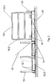
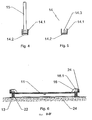
- the moving platform (11) is formed by a metal structure with two double “T" sections (13), the wings (13.1) of which the upper, see figure 7 , serves as a track for the wheels (16.1) fitted in the boxes (16), which turn on a horizontal axle.
- the boxes (16) are secured close to the corners of the moving platform (11), and sliding by the same on these sections (13), as can also be seen in figure 2 .
- the support base (21) on which the moving platform is supported (11) comprises sections (13) which are maintained at a certain distance, the width of the platform (13) with the aid of smaller reinforcement sections (23), and the boxes (16) are welded to said moving platform (11) partially, as can be seen in figure 1 .
- the platform (10) is secured to the flooring plane (24) with the aid of supports (14) which as can be seen in figures 1 and 2 , are welded to the sections (13), with a configuration as displayed in figures 4 and 5 in "U"-shaped base (14.2) and vertical arms (14.1), with a pivot (14.3) on the base (14.2), on which a post (15) rests, whose upper end (not represented in the figures) rests on the upper framework.
- the platform (10) has protections to avoid workers handling this sliding platform (10) to fall off, see figures 2 and 3 , these means of protection comprise, among others:
- the side railings (19), see figure 2 comprise longitudinal beams (19.1) which are welded to the props (19.2), the railing (19) in turn is joined by any known means to the platform (11) by means of the supports (19.3), as can be seen in figure 1 .
- the transversal movable railings (20) are fitted on support base by means of the props (20.2), as can be seen in figure 3 , and at the lower side of the props (20.1) some pivots (30) are welded which work in collaboration with other vertical pivots (17) welded to the boxes (16) as can be seen in figure 1 , so that when the moving platform (11) advances to the exterior of the building, the pivot (30) on hitting the pivot (17) makes the railings (20) turn approximately 90°, and the railings (20) are parallel to the sections (13), until the moving platform (11) is overhanging.
- Another feature of the invention is the foldable platform (12) that is a sloping plane in resting position as represented in figure 2 , so that forklifts and transpallets can operate on the sliding platform (10), without any problem or interference due to steps or steep slopes, so that thanks to its slight slope, when the transpallet goes up the platform (12) its arms are located under the pallet, containing construction material, and this is lifted and may be removed from the moving platform.
- a catch (18) has been designed which, as can be seen in figure 7 , has a hollow body (18.4) with a handle (18.1) welded to a vertical shaft (18.2) with a spring (18.3) which surrounds the shaft (18.2), so that when the operator wishes to move the moving platform (12) he lifts the shaft (18.2), and the moving platform (12) is unlocked when this shaft (18.2) leaves its orifice (13.3), and it can be locked again (12) in said orifice (13.3) in the desired point, freeing the shaft (18.2) in the other orifice (13.3) located in front of or behind the previous one.
- the foldable platform (12) In loading position, the foldable platform (12) is perpendicular to the plane of the flooring plane (24) offering supplementary protection to the operator, who cannot access the moving platform (11), finding the platform (12) vertical with the transversal railings (20) perpendicular to the sections (13).
Landscapes
- Engineering & Computer Science (AREA)
- Architecture (AREA)
- Mechanical Engineering (AREA)
- Civil Engineering (AREA)
- Structural Engineering (AREA)
- Forklifts And Lifting Vehicles (AREA)
Applications Claiming Priority (1)
| Application Number | Priority Date | Filing Date | Title |
|---|---|---|---|
| ES201030391 | 2010-04-28 |
Publications (1)
| Publication Number | Publication Date |
|---|---|
| EP2383405A2 true EP2383405A2 (fr) | 2011-11-02 |
Family
ID=44359653
Family Applications (1)
| Application Number | Title | Priority Date | Filing Date |
|---|---|---|---|
| EP11380038A Withdrawn EP2383405A2 (fr) | 2010-04-28 | 2011-04-27 | Plateforme de chargement coulissante pour la construction |
Country Status (1)
| Country | Link |
|---|---|
| EP (1) | EP2383405A2 (fr) |
Cited By (12)
| Publication number | Priority date | Publication date | Assignee | Title |
|---|---|---|---|---|
| CN106320716A (zh) * | 2015-07-01 | 2017-01-11 | 上海宝冶集团有限公司 | 高层建筑施工用可调式分区卸料平台 |
| CN109734004A (zh) * | 2018-12-27 | 2019-05-10 | 山东大汉建设机械股份有限公司 | 一种方便拆装的塔机平台及其安装方法 |
| CN111206759A (zh) * | 2020-03-28 | 2020-05-29 | 中国二十二冶集团有限公司 | 建筑工程现场施工平台 |
| CN111502303A (zh) * | 2020-05-14 | 2020-08-07 | 南京古发建筑装饰工程有限公司 | 一种用于高层建筑施工的装配式卸料平台 |
| CN111663788A (zh) * | 2020-06-16 | 2020-09-15 | 北京欧斯度科技有限公司 | 一种便于收纳的卸料平台 |
| CN113565325A (zh) * | 2021-07-29 | 2021-10-29 | 戴巍 | 一种土建工程定向移动式支撑平台 |
| CN113756591A (zh) * | 2021-09-10 | 2021-12-07 | 上海建工集团股份有限公司 | 复合卸料平台及其施工方法 |
| CN114458022A (zh) * | 2021-12-22 | 2022-05-10 | 上海建工四建集团有限公司 | 室内电梯井材料运输卸料钢平台 |
| CN115419281A (zh) * | 2022-09-14 | 2022-12-02 | 陕西建工机械施工集团有限公司 | 大跨度空间钢结构的滑动支座水平力卸载装置及卸载方法 |
| CN115898027A (zh) * | 2023-02-13 | 2023-04-04 | 浙江中南绿建科技集团有限公司 | 一种大跨度屋面结构分段提升拼装方法 |
| CN117248740A (zh) * | 2023-10-24 | 2023-12-19 | 安徽星辰智创信息科技有限公司 | 一种公共建筑施工用卸料平台 |
| CN120867540A (zh) * | 2025-09-19 | 2025-10-31 | 闽南理工学院 | 一种用于建筑施工的悬挑式卸料平台 |
-
2011
- 2011-04-27 EP EP11380038A patent/EP2383405A2/fr not_active Withdrawn
Cited By (12)
| Publication number | Priority date | Publication date | Assignee | Title |
|---|---|---|---|---|
| CN106320716A (zh) * | 2015-07-01 | 2017-01-11 | 上海宝冶集团有限公司 | 高层建筑施工用可调式分区卸料平台 |
| CN109734004A (zh) * | 2018-12-27 | 2019-05-10 | 山东大汉建设机械股份有限公司 | 一种方便拆装的塔机平台及其安装方法 |
| CN111206759A (zh) * | 2020-03-28 | 2020-05-29 | 中国二十二冶集团有限公司 | 建筑工程现场施工平台 |
| CN111502303A (zh) * | 2020-05-14 | 2020-08-07 | 南京古发建筑装饰工程有限公司 | 一种用于高层建筑施工的装配式卸料平台 |
| CN111663788A (zh) * | 2020-06-16 | 2020-09-15 | 北京欧斯度科技有限公司 | 一种便于收纳的卸料平台 |
| CN113565325A (zh) * | 2021-07-29 | 2021-10-29 | 戴巍 | 一种土建工程定向移动式支撑平台 |
| CN113756591A (zh) * | 2021-09-10 | 2021-12-07 | 上海建工集团股份有限公司 | 复合卸料平台及其施工方法 |
| CN114458022A (zh) * | 2021-12-22 | 2022-05-10 | 上海建工四建集团有限公司 | 室内电梯井材料运输卸料钢平台 |
| CN115419281A (zh) * | 2022-09-14 | 2022-12-02 | 陕西建工机械施工集团有限公司 | 大跨度空间钢结构的滑动支座水平力卸载装置及卸载方法 |
| CN115898027A (zh) * | 2023-02-13 | 2023-04-04 | 浙江中南绿建科技集团有限公司 | 一种大跨度屋面结构分段提升拼装方法 |
| CN117248740A (zh) * | 2023-10-24 | 2023-12-19 | 安徽星辰智创信息科技有限公司 | 一种公共建筑施工用卸料平台 |
| CN120867540A (zh) * | 2025-09-19 | 2025-10-31 | 闽南理工学院 | 一种用于建筑施工的悬挑式卸料平台 |
Similar Documents
| Publication | Publication Date | Title |
|---|---|---|
| EP2383405A2 (fr) | Plateforme de chargement coulissante pour la construction | |
| US9273475B1 (en) | Cement industry gangway | |
| US10703591B2 (en) | Loading platform | |
| KR101641107B1 (ko) | 승강식 비계장치 | |
| KR102326550B1 (ko) | 관절식 암을 갖는 트롤리 | |
| GB2422141A (en) | Elevating working platform for clamping to the framework of a building as the building is constructed | |
| WO2015066761A1 (fr) | Système d'entreposage roulant pour conteneurs | |
| JP2520780B2 (ja) | 建設現場用のランディングプラットフォ―ムおよび高架保護体 | |
| KR101617602B1 (ko) | 휠 캠버 변화에 의한 들어올림 효과를 갖는 팔레트를 들어올리고 이동시키기 위한 수동식 롤링 디바이스 | |
| US20070261917A1 (en) | Foldable work platform | |
| CN205955234U (zh) | 移动式卸料平台 | |
| EP3369863B1 (fr) | Élément de barrière de sécurité | |
| EP2119591A1 (fr) | Système antichute | |
| ES1072383U (es) | Plataforma de carga deslizante para la construccion. | |
| DK181951B1 (en) | Temporary guardrail for use when unloading objects from trucks and trailers | |
| AU2012101697A4 (en) | Skid Board | |
| JP5778943B2 (ja) | 高所作業車 | |
| GB2473284A (en) | Mobile fall prevention assembly with twin booms | |
| CA1334831C (fr) | Engin de levage remorquable a fleche repliable comportant des canaux de guidage de chariot elevateur | |
| JP3175648U (ja) | 重量物の吊り上げ移載装置 | |
| RU131709U1 (ru) | Малогабаритный быстромонтируемый кран (мбмк) | |
| GB2478042A (en) | Loading platform | |
| HK1241435A1 (zh) | 装载平台 | |
| PL68202Y1 (pl) | Platforma załadowcza |
Legal Events
| Date | Code | Title | Description |
|---|---|---|---|
| 17P | Request for examination filed |
Effective date: 20110509 |
|
| AK | Designated contracting states |
Kind code of ref document: A2 Designated state(s): AL AT BE BG CH CY CZ DE DK EE ES FI FR GB GR HR HU IE IS IT LI LT LU LV MC MK MT NL NO PL PT RO RS SE SI SK SM TR |
|
| AX | Request for extension of the european patent |
Extension state: BA ME |
|
| PUAI | Public reference made under article 153(3) epc to a published international application that has entered the european phase |
Free format text: ORIGINAL CODE: 0009012 |
|
| STAA | Information on the status of an ep patent application or granted ep patent |
Free format text: STATUS: THE APPLICATION IS DEEMED TO BE WITHDRAWN |
|
| 18D | Application deemed to be withdrawn |
Effective date: 20131101 |