EP2383432A1 - Pumpensystem - Google Patents
Pumpensystem Download PDFInfo
- Publication number
- EP2383432A1 EP2383432A1 EP10161453A EP10161453A EP2383432A1 EP 2383432 A1 EP2383432 A1 EP 2383432A1 EP 10161453 A EP10161453 A EP 10161453A EP 10161453 A EP10161453 A EP 10161453A EP 2383432 A1 EP2383432 A1 EP 2383432A1
- Authority
- EP
- European Patent Office
- Prior art keywords
- pump
- wellbore
- chamber
- pumping system
- liquid
- Prior art date
- Legal status (The legal status is an assumption and is not a legal conclusion. Google has not performed a legal analysis and makes no representation as to the accuracy of the status listed.)
- Withdrawn
Links
Images

Classifications
-
- E—FIXED CONSTRUCTIONS
- E21—EARTH OR ROCK DRILLING; MINING
- E21B—EARTH OR ROCK DRILLING; OBTAINING OIL, GAS, WATER, SOLUBLE OR MELTABLE MATERIALS OR A SLURRY OF MINERALS FROM WELLS
- E21B43/00—Methods or apparatus for obtaining oil, gas, water, soluble or meltable materials or a slurry of minerals from wells
- E21B43/12—Methods or apparatus for controlling the flow of the obtained fluid to or in wells
- E21B43/121—Lifting well fluids
- E21B43/128—Adaptation of pump systems with down-hole electric drives
-
- F—MECHANICAL ENGINEERING; LIGHTING; HEATING; WEAPONS; BLASTING
- F04—POSITIVE - DISPLACEMENT MACHINES FOR LIQUIDS; PUMPS FOR LIQUIDS OR ELASTIC FLUIDS
- F04B—POSITIVE-DISPLACEMENT MACHINES FOR LIQUIDS; PUMPS
- F04B47/00—Pumps or pumping installations specially adapted for raising fluids from great depths, e.g. well pumps
- F04B47/06—Pumps or pumping installations specially adapted for raising fluids from great depths, e.g. well pumps having motor-pump units situated at great depth
Definitions
- the present invention relates to a wellbore pumping system for unloading liquid from a wellbore comprising well fluid, such as gas, having a wellbore pressure, comprising a pump having an inlet and an outlet, a tubing fluidly connected to the outlet of the pump, and a driving unit connected and powered by a cable, such as a wireline, for driving the pump. Furthermore, the invention relates to a wellbore pumping method.
- water particles may be present in a well fluid or be produced while being transported up through the wellbore or borehole, and some of these water particles may condense on the inner face of the wellbore and subsequently flow along the inner face down to the bottom of the wellbore. In this way, the water accumulates at the bottom of the well and will subsequently block the passage of gas from the formation into the wellbore.
- a pump When the water has reduced or even stopped the passage of gas from the wellbore, a pump is connected to a drill pipe and lowered into the well in order to pump the water up through the drill pipe.
- the existing pumping solutions are very large and demand the presence of a drill pipe or the like solutions.
- a wellbore pumping system for unloading liquid from a wellbore comprising well fluid, such as gas, having a wellbore pressure, comprising:
- the first moving member may divide the housing into the first chamber and a second chamber.
- the driving unit may comprise a one-way valve arranged between the inlet and the first chamber and a second one-way valve arranged between the outlet and the first chamber, enabling that liquid to be sucked into the first chamber and subsequently forced out through the second one-way valve by displacing the moving member.
- the wellbore pumping system may further comprise a compensator comprising a compensator chamber having a compensator moving member displaceable in the compensator chamber and dividing the compensator chamber into a first chamber section and a second chamber section, wherein the first chamber section is in fluid communication with the well fluid, and the second chamber of the reciprocating pump is in fluid communication with the second chamber section.
- the purpose of this is to create a pressure equilibrium between the two chambers to ensure that that dirty liquid from the wellbore does not leak into the clean side of the pump.
- the first chamber may be filled with liquid during pumping of the liquid
- the second chamber may be filled with a second liquid
- the second liquid may be a dielectric fluid, such as mineral oil, castor oil, Polychlorinated biphenyls (PCBs), etc.
- a dielectric fluid such as mineral oil, castor oil, Polychlorinated biphenyls (PCBs), etc.
- the tubing may be made of a non-metallic material.
- the tubing may be made of a material more flexible than iron or steel.
- the tubing may be made of plastic, syntactic or natural rubber or a composite.
- the pumping unit may be surrounded by a cavity filled with the second liquid and be in fluid communication with the second chamber of the pumping unit.
- the pump may have a plurality of pumping units, and the moving members may be arranged so that when one moving member moves in one direction, another moving member moves in an opposite direction.
- the reciprocating pump may be a radial or axial pump.
- a first moving member may displace a first volume of liquid when moved in one direction
- a second moving member may displace a second volume of liquid when moved in another direction opposite the first direction, wherein the first and the second volume are substantially the same size
- a first moving member may displace a first volume of liquid when moved in one direction
- two or more moving members may displace a second volume of liquid when moved in one direction, wherein the first and the second volume are substantially the same size
- the wellbore pumping system may further comprise a control unit for activating the pump.
- control unit may have a measuring unit for measuring the power used by the driving unit for driving the pump.
- the pump is stopped again.
- the value is set at the power used by the driving unit when it drives a pump which pumps up no or only a small amount of liquid. In this way, it is possible to save power when no or only a small amount of liquid is present in the wellbore.
- the system waits a predetermined period of time and then reactivates the pump while measuring the power. When the system has in this way activated the pump at the predetermined time interval a predetermined number of times, the time interval is extended.
- the moving member may be a solid or a flexible member/plate/disk.
- the number of moving members may be at least two]
- the measuring means may be used for detecting the level of energy consumption during the pumping activity.
- control unit may comprise a receiving means for receiving the level of the energy consumption or power needed for driving the pump as well as a calculator unit for comparing the consumption with a predetermined minor value.
- the reciprocating pump may be a diaphragm pump, a piston pump or a plunger pump.
- a filter device may be placed in front of or be an integrated part of the inlet.
- the pump may be activated when a predetermined period of time has passed since the last stop of the pump.
- This period of time may increase from activation to activation or when a predetermined number of activation attempts have been made if the energy consumption or power is lower than the predetermined value.
- the time period may be between 5 minutes and 1 month.
- the wellbore pumping system may further comprise a fixation means for fixating the pump inside the wellbore.
- the driving unit may comprise a starting means which during activation of the pump reduces a torque delivered to a drive shaft driving the pump.
- a starting means is also called “soft starters” and is used in combination with AC electrical motors.
- the driving unit may be an electrical motor or a hydraulic motor.
- the wellbore pumping system may further comprise a driving tool for moving the pumping system inside the wellbore.
- the driving tool may be a downhole tractor.
- the present invention furthermore relates to a method comprising the steps of:
- the invention relates to a method further comprising the step of reactivating the pump after a predetermined period of time.
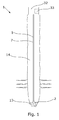
- Fig. 1 shows a wellbore pumping system 1 according to the invention for pumping liquid 13 from a wellbore to above surface.
- the borehole comprises well fluid 14, such as gas, at a certain wellbore pressure P.
- well fluid 14 such as gas
- P wellbore pressure
- water particles may be present in the well fluid or be produced while being transported up through the wellbore or borehole.
- some of these water particles condense on the inner face of the wellbore and subsequently flow along the inner face down to the bottom of the wellbore.
- the wellbore pumping system 1 In order to pump the water up from the bottom of the well, the wellbore pumping system 1 is submerged into the well by means of a wireline, as shown in Fig. 1 .
- the wellbore pumping system 1 comprises a small flexible tubing 5 in which the water flows while being pumped to above surface.
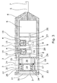
- the wellbore pumping system 1 comprises a pump 2 for pumping liquid 13 to above surface or to another place, and the wellbore pumping system furthermore comprises a driving unit 6 used to activate and drive the pump 2, as shown in Fig. 2 .
- the driving unit 6 is connected to and powered by a cable 7 which may be part of the tubing 5 or a separate cable, such as a wireline.
- the wellbore pumping system 1 comprises a compensator 22 to compensate for the high well pressure at the bottom of the well.
- the compensator 22 supplies the pump 2 with fluid if the well pressure surrounding the pump increases, ensuring that the walls of the pump do not collapse. If the pressure drops again, the compensator 22 is able to accumulate the fluid inside the pump 2 to ensure that the pump does not bulge outwards.
- the compensator 22 enables the pumping system 1 to have thin walls, causing it to be less expensive to produce.
- a thin wall construction weighs less than prior art pumping systems and thus does not put as much stress on the tubing as heavier prior art systems, making it possible to use a smaller tubing.
- the pump 2 has an inlet 3 for letting liquid 13 into the pump and an outlet 4 which is fluidly connected to the tubing 5 used for transporting the liquid.
- the pump 2 is a reciprocating pump since this type of pump is a simple pump which is also able to pump small amounts of liquid.
- the pumping system 1 can be used as a permanent system arranged inside the well during gas production, eliminating the need for an additional larger pumping system.
- the pump 2 is a radial piston pump comprising two pumping units 8 having a first moving member 9, such as a piston, being displaceable in a housing 10 and dividing the housing into a first chamber 11 and a second chamber 12.
- the liquid 13 is pumped into the first chamber 11 from the wellbore, further out through the outlet 4 and into the tubing 5.
- the first chamber 11 is situated on the "dirty" side of the moving member 9, and the piston 8 is able to push the dirt in front of itself when moving towards the inlet 3. In this way, any dirt or unwanted elements are forced to flow with the well fluid 14 when being pumped back out through the outlet 4.
- the second chamber 12 is filled with a second fluid which is cleaner than the well fluid 14, minimising the risk of dirt from the wellbore entering the vital parts of the pump 2.
- the second fluid is often a dielectric fluid also used in transformers and is therefore also called a "transformer fluid".
- the second liquid may be a mineral oil, castor oil, polychlorinated biphenyls (PCBs) or the like.
- the pumping unit 8 comprises a one-way valve 15 arranged between the inlet 3 and the first chamber 11 and a second one-way valve 16 arranged between the outlet 4 and the first chamber 12. This means that when the moving member 9 is forced away from the inlet 3, thereby increasing the volume of the first chamber 11, the well fluid 14 fills the first chamber 11, but when the moving member 9 moves back towards the inlet 3, the fluid 14 is unable to flow back in through the inlet 3. The liquid 13 sucked into the first chamber 11 is subsequently forced out through the second one-way valve.
- the moving members 9 are arranged so that when one moving member moves in one direction, another moving member moves in an opposite direction. This means that during one stroke, one piston is in its top position, and the other piston is in its bottom position.
- the volume V1 of the first chamber 11 of one pumping unit 8 is substantially the same as the volume V2 of the second chamber 12 of the other pumping unit.
- the top position is the position nearest the inlet 3 and outlet 4, and the bottom position is the position furthest away from the inlet 3 and the outlet 4.
- the volume of the first chamber 11 of one pumping unit 8 is the same as the volume of the second chamber 12 of the other pumping unit.
- one pumping unit feeds the other with the second fluid, ensuring that the "dirty" well fluid 14 is not sucked into the "clean" side of the pumping unit 8.
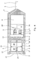
- the wellbore pumping system 1 further comprises a compensator 22, as shown in Fig. 3 .
- the compensator 22 comprises a compensator chamber 17 having a compensator moving member 18 acting like a piston displaceable in the compensator chamber 17 and dividing the compensator chamber into a first chamber section 19 and a second chamber section 20.
- the first chamber section 19 is in fluid communication with the well fluid 14 through an opening 23 in the wall of the chamber and through an opening 24 in the wall of the wellbore pumping system 1.
- the second chamber 12 of the pump is in fluid communication with the cavity 21 surrounding the housing 10 of the pumping units 8 and with the second chamber section 20. In this way, the well fluid 14 presses on the dirty side of the compensator moving member 18, equalising the pressure inside the pump 2 to be the same as the wellbore pressure P.
- a screen or filter 30 is arranged in the openings 24 so that scales or other particles cannot enter the compensator 22 or the pump 2 and deteriorate their function.
- the compensator moving member 18 is displaceable inside the compensator chamber 17, and due to an O-ring arranged between the compensator moving member 18 and the inside wall of the compensator chamber 17, the dirty well fluid is not mixed with the clean second fluid inside the pump 2.
- the compensator moving member 18 is arranged in a sliding relationship with two sliding rods 25. In this way, the compensator moving member 18 does not tilt while moving inside the compensator chamber 17.
- flexible elements 34 such as springs, are arranged around the rods 25 so that the fluid in the cavity 21 surrounding the housings 10 of the pumping units 8 has a higher pressure than that of the well fluid 14. This ensures that the well fluid 14 does not enter the cavity 21. This is especially useful if the well fluid 14 is very aggressive.
- the driving unit 6 rotates a drive shaft 26 on which cams 27 are arranged for forcing a piston rod 28 of the piston up and down or back and forward.
- the flow paths connecting the openings 24 of the pumping system 1 and the inlet of the pumping units 8 may be hollow spaces or drilled bores on the side of the pumping system 1, or a combination thereof.
- the drive shaft 26 penetrates the wall between the pump 2 and the driving unit 6 and is arranged with a sealing arrangement ensuring that the fluid surrounding the driving unit 6, such as a motor, is not mixed with the second fluid.
- the fluid inside and/or surrounding the motor may be the same as the second fluid, meaning that leaks in the transition between the pump and the driving unit around the drive shaft do not affect the function of the motor or the pump.
- inlet 3 and outlet 4 are not in the same cross-sectional plane, but the outlet channel 4 is merely shown as a dotted line for illustration purposes only.
- the pump 2 is an axial piston pump comprising two pumping units 8.
- Each unit 8 has a first moving member 9 displaceable in a housing 10 for sucking well fluid 14 into and out of the first chamber 11.
- the moving member 9 is a piston connected to an inclined plate 29 which is rotated by the drive shaft 26 of the driving unit 6.
- the volume V1 of the first chamber 11 is increased, and well fluid 14 is sucked into the chamber. Subsequently, the well fluid 14 is forced out through the outlets 4 and into the tubing 5 when the piston moves towards the outlet 4.
- the compensator 22 has the same design as the compensator in Fig. 3 , but has one sliding rod 25 instead of two.
- the pumping system 1 has several openings for letting well fluid 14 into the pump 2.
- the system 1 may have openings in one end of the system as well as along its sides 31. By having openings in the wall of the pumping system both at the end of the system and along the sides, it is possible to use the wellbore pumping system 1 even though it is somewhat tilted and not in an upright position with its longitudinal axis parallel with the longitudinal axis of the wellbore.
- the inner diameter of the tubing is 50-1 mm, preferably 30-5 mm and more preferably 20-5 mm.
- the tubing 5 may be in connection with the cable feeding power to the driving unit 6, e.g. in the form of an umbilical comprising both a fluid tubing and electrical cables.
- the pump 2 is also able to pump small amounts of fluid.
- a thin-walled reciprocating pump according to the present invention cannot pump the fluid all the way up to above surface if the diameter of the tubing 5 is too large since the pump 2 cannot not lift a liquid column having a large diameter, such as the diameter of a drill pipe or coiled tubing.
- the pumps made for drill pipes or coiled tubing are larger pumps designed for a substantially larger pumping capacity. The design of prior art pumps is therefore more complex and expensive.
- the pump 2 of the present invention has a simpler and less expensive design, meaning that a pump can be submerged for a longer time period of time and be thrown away when not functioning anymore.
- the driving unit 6 and the compensator 22 may be reused, but may also be disposable, meaning that the entire wellbore pumping system may be a disposable system.
- the amount of power needed for driving the pump 2 is estimated to less than 2 horsepower per day, preferably less than 1.5 horsepower if the well has a depth of 10,000 feet and accumulates a water rate of 10 barrels per day. If the pumping system 1 is submerged for a longer period of time for precautionary reasons, the pump 2 does not have to be as large as the known pumping systems which are submerged when production has stopped and need to pump up a large amount of water very quickly.
- the wellbore pumping system 1 has three pumping units 6, meaning that a first moving member 9 displaces a first volume V1 of liquid when moved in a first direction, and the two other moving members displace a second volume V2 of liquid when moved in the opposite direction of the first direction, wherein the first and the second volume are substantially the same size.
- the pumping system 1 does not need fixation devices to fixate the system in relation to the wellbore system since the movements of the moving members outbalance each other.
- the wellbore system 1 also comprises a control unit 32 for activating the pump.
- the control unit 32 is primarily arranged above surface, but part of it may be arranged in the part of the system being submerged into the wellbore.
- the control unit 32 sends a signal to the driving unit 6 to start or stop.
- the driving unit 6 comprises a starting means which during activation of the pump 2 reduces the torque delivered to a drive shaft driving the pump.
- the control unit 32 furthermore comprises a means for controlling the driving unit 6 to reduce the torque delivered to the drive shaft 26.
- the starting means is also called “soft starters" and is primarily used in combination with AC electrical motors. Using a starting means performing a "soft" start eliminates the need for a fixation device for fixating the system in relation to the wellbore.
- control unit 32 may have a measuring unit 33 for measuring the power used by the driving unit 6 for driving the pump 2. If the measurements of the measuring unit 33 show that the driving unit 6 uses less power than a predetermined value, the pump is stopped again. The value is higher than the amount of power used by the driving unit 6 for driving a pump 2 when the pump pumps up no or only a small amount of liquid. This makes it possible to save power when no or only a small amount of liquid is present in the wellbore.
- the system 1 After stopping the driving unit 6, the system 1 waits a predetermined period of time period and then reactivates the pump 2 while measuring the power. When the system has in this way activated the pump 2 at the predetermined time interval a predetermined number of times, and the power is still not higher than the predetermined value, the time interval is extended. In this way, the measuring means is used for detecting the level of energy consumption during the pumping activity, and the control unit 32 controls the driving unit 6 based on the measured power.
- the wellbore pumping system 1 does not consume any more energy than needed for pumping up the liquid and is thus more environmentally friendly.
- the period of time from activation to activation is increased once again.
- the time period is between 5 minutes and 1 month, preferably between 5 minutes and 2 weeks and more preferably between 10 minutes and 1 week.
- the wellbore pumping system When in use, the wellbore pumping system is entered into the wellbore, and when in place, the pump 2 is activated by sending a start signal to the driving unit 6 to activate the pump. Subsequently, the measuring unit 33 measures the power or level of energy consumption used by the driving unit 6 for driving the pump 2.
- the control unit 32 determines whether the power is higher than a predetermined value and if it is not, the pump is stopped again. After a predetermined period of time, the pump 2 is reactivated, and the power is measured again. If the power is lower than a predetermined value, the pump 2 is stopped again.
- This start and stop procedure is repeated a predetermined number of times, and then the time period is prolonged.
- the start and stop procedure may be repeated 3-30 times, preferably 5-20 times and more preferably 5-10 times when the power consumption is lower than the predetermined value. The number of repetitions performed before increasing the time period may vary depending on the time period.
- control unit 32 comprises a receiving means for receiving the level of energy consumption X or power needed for driving the pump 2 and a calculator unit for comparing the consumption with a predetermined minor value.
- the reciprocating pump may be a piston pump, but may also be a diaphragm pump or a plunger pump.
- a screen 30 or the like filter device may be placed in front of or as an integrated part of the inlet 3. It may also be arranged inside the walls of the pumping system 1 so that fluid entering several openings 24 has to flow through the same screen or filter device.
- the wellbore pumping system 1 may comprise a fixation means for fixating the pump 2 in the wellbore, e.g. if the driving unit 6 does not have a starting means able to perform a so-called "soft start".
- the driving unit 6 may be any kind of means capable of driving the pump 2.
- the driving unit 6 may be an electrical motor or a hydraulic motor.
- the driving unit 6 may also comprise a compensator ensuring that the driving unit do not collapse or bulge outwards. Furthermore, if the driving unit 6 is compensated in the same way as the wellbore pumping system 1, the second fluid surrounding the pump 2 will not penetrate the transition between the pump and the driving unit where the drive shaft 26 of the driving unit enters the pump. Neither will the fluid inside the driving unit 6 mix with the second fluid in the pump 2 since the pressures inside the pump and the driving unit are the same.
- fluid or well fluid 14 is meant any kind of fluid which may be present in oil or gas wells downhole, such as natural gas, oil, oil mud, crude oil, water, etc.
- gas is meant any kind of gas composition present in a well, completion, or open hole
- oil is meant any kind of oil composition, such as crude oil, an oil-containing fluid, etc.
- Gas, oil, and water fluids may thus all comprise other elements or substances than gas, oil, and/or water, respectively.
- a casing any kind of pipe, tubing, tubular, liner, string etc. used downhole in relation to oil or natural gas production.
- a downhole tractor can be used to push the system all the way into position in the well.
- a downhole tractor is any kind of driving tool capable of pushing or pulling tools in a well downhole, such as a Well Tractor®.
Landscapes
- Engineering & Computer Science (AREA)
- Geology (AREA)
- Life Sciences & Earth Sciences (AREA)
- Mining & Mineral Resources (AREA)
- Environmental & Geological Engineering (AREA)
- Fluid Mechanics (AREA)
- Physics & Mathematics (AREA)
- General Life Sciences & Earth Sciences (AREA)
- Geochemistry & Mineralogy (AREA)
- Mechanical Engineering (AREA)
- General Engineering & Computer Science (AREA)
- Details Of Reciprocating Pumps (AREA)
- Reciprocating Pumps (AREA)
- Structures Of Non-Positive Displacement Pumps (AREA)
- Jet Pumps And Other Pumps (AREA)
Priority Applications (8)
| Application Number | Priority Date | Filing Date | Title |
|---|---|---|---|
| EP10161453A EP2383432A1 (de) | 2010-04-29 | 2010-04-29 | Pumpensystem |
| BR112012027251A BR112012027251A2 (pt) | 2010-04-29 | 2011-04-29 | sistema de bombeamento |
| CA2796958A CA2796958A1 (en) | 2010-04-29 | 2011-04-29 | Pumping system |
| US13/695,469 US9045976B2 (en) | 2010-04-29 | 2011-04-29 | Pumping system |
| RU2012150458/03A RU2566349C2 (ru) | 2010-04-29 | 2011-04-29 | Откачивающая система |
| EP11716568A EP2564019A1 (de) | 2010-04-29 | 2011-04-29 | Pumpensystem |
| CN201180021440.XA CN102859115B (zh) | 2010-04-29 | 2011-04-29 | 泵送系统 |
| PCT/EP2011/056827 WO2011135069A1 (en) | 2010-04-29 | 2011-04-29 | Pumping system |
Applications Claiming Priority (1)
| Application Number | Priority Date | Filing Date | Title |
|---|---|---|---|
| EP10161453A EP2383432A1 (de) | 2010-04-29 | 2010-04-29 | Pumpensystem |
Publications (1)
| Publication Number | Publication Date |
|---|---|
| EP2383432A1 true EP2383432A1 (de) | 2011-11-02 |
Family
ID=42315863
Family Applications (2)
| Application Number | Title | Priority Date | Filing Date |
|---|---|---|---|
| EP10161453A Withdrawn EP2383432A1 (de) | 2010-04-29 | 2010-04-29 | Pumpensystem |
| EP11716568A Withdrawn EP2564019A1 (de) | 2010-04-29 | 2011-04-29 | Pumpensystem |
Family Applications After (1)
| Application Number | Title | Priority Date | Filing Date |
|---|---|---|---|
| EP11716568A Withdrawn EP2564019A1 (de) | 2010-04-29 | 2011-04-29 | Pumpensystem |
Country Status (7)
| Country | Link |
|---|---|
| US (1) | US9045976B2 (de) |
| EP (2) | EP2383432A1 (de) |
| CN (1) | CN102859115B (de) |
| BR (1) | BR112012027251A2 (de) |
| CA (1) | CA2796958A1 (de) |
| RU (1) | RU2566349C2 (de) |
| WO (1) | WO2011135069A1 (de) |
Cited By (3)
| Publication number | Priority date | Publication date | Assignee | Title |
|---|---|---|---|---|
| FR3019595A1 (fr) * | 2014-04-03 | 2015-10-09 | Hydro Leduc | Dispositif de pompage |
| WO2017117084A3 (en) * | 2015-12-29 | 2017-10-05 | Ge Oil & Gas Esp, Inc. | Linear hydraulic pump for submersible applications |
| WO2023007193A1 (en) * | 2021-07-30 | 2023-02-02 | Kingdom Innovative Technologies Ltd | Borehole water pump |
Families Citing this family (15)
| Publication number | Priority date | Publication date | Assignee | Title |
|---|---|---|---|---|
| EP2516792A4 (de) | 2009-12-23 | 2015-05-06 | Bp Corp North America Inc | Pumpensystem mit geringem volumen ohne bohranlage |
| WO2015030931A2 (en) * | 2013-08-27 | 2015-03-05 | Exxonmobil Upstream Research Company Corp-Urc-Sw359 | Systems and methods for artificial lift via a downhole positive displacement pump |
| CA2888027A1 (en) | 2014-04-16 | 2015-10-16 | Bp Corporation North America, Inc. | Reciprocating pumps for downhole deliquification systems and fluid distribution systems for actuating reciprocating pumps |
| EP3153656A1 (de) * | 2015-10-06 | 2017-04-12 | Welltec A/S | Bohrlochdurchflussvorrichtung |
| EP3263829A1 (de) * | 2016-06-28 | 2018-01-03 | Welltec A/S | Bohrlochbohrsystem |
| EP3704351A4 (de) * | 2017-11-02 | 2021-03-31 | Q.E.D. Environmental Systems, Inc. | Flüssigkeitsstandsensorsystem |
| CN112702982B (zh) * | 2018-06-05 | 2023-12-19 | 卡尔蔡司白内障医疗技术公司 | 眼科显微手术工具、系统和使用方法 |
| EP3917468B1 (de) | 2019-02-01 | 2023-11-15 | Carl Zeiss Meditec Cataract Technology Inc. | Ophthalmische schneidinstrumente mit integrierter absaugpumpe |
| EP3968912B1 (de) | 2019-05-17 | 2026-05-06 | Carl Zeiss Meditec Cataract Technology Inc. | Ophthalmische schneidinstrumente mit integrierter absaugpumpe |
| WO2020247165A2 (en) | 2019-06-07 | 2020-12-10 | Carl Zeiss Meditec Cataract Technology Inc. | Multi-stage trigger for ophthalmology cutting tool |
| CN110594211A (zh) * | 2019-08-12 | 2019-12-20 | 大家原油压工业有限公司 | 节能型油压控制系统 |
| US11091988B2 (en) | 2019-10-16 | 2021-08-17 | Saudi Arabian Oil Company | Downhole system and method for selectively producing and unloading from a well |
| US10883488B1 (en) * | 2020-01-15 | 2021-01-05 | Texas Institute Of Science, Inc. | Submersible pump assembly and method for use of same |
| SI4093970T1 (sl) | 2020-01-23 | 2025-08-29 | Hess Corporation | Sklop potopne črpalke in način njene uporabe |
| SI4093971T1 (sl) | 2020-01-23 | 2025-08-29 | Hess Corporation | Sklop potopne črpalke in način njene uporabe |
Citations (5)
| Publication number | Priority date | Publication date | Assignee | Title |
|---|---|---|---|---|
| US4548552A (en) * | 1984-02-17 | 1985-10-22 | Holm Daniel R | Dual valve well pump installation |
| EP0310254A2 (de) * | 1987-09-07 | 1989-04-05 | Framo Developments (U.K.) Limited | Hubkolben-Pumpeinheit |
| US5261791A (en) * | 1992-03-09 | 1993-11-16 | Advanced Remediation Technologies | Method and apparatus for recovering pollutants from an aquifer |
| US20020189805A1 (en) * | 2001-06-13 | 2002-12-19 | Weatherford/Lamb, Inc. | Double-acting reciprocating downhole pump |
| US20060124298A1 (en) * | 2004-12-14 | 2006-06-15 | Howard Geier | Pumping water from a natural gas well |
Family Cites Families (13)
| Publication number | Priority date | Publication date | Assignee | Title |
|---|---|---|---|---|
| US2032000A (en) * | 1933-09-15 | 1936-02-25 | Reda Pump Company | Means for raising fluid from deep oil and water wells |
| US2431492A (en) * | 1945-07-11 | 1947-11-25 | William G Klein | Oil well pump |
| US2972955A (en) * | 1957-03-21 | 1961-02-28 | Richter Harald | Submersible pump |
| US3486454A (en) * | 1968-04-16 | 1969-12-30 | Borg Warner | Piston pump with remote control of displacement |
| US3589838A (en) * | 1969-11-19 | 1971-06-29 | Borg Warner | Submersible multiple-acting floating piston deep well pump |
| US4476923A (en) * | 1980-07-21 | 1984-10-16 | Walling John B | Flexible tubing production system for well installation |
| US4425087A (en) * | 1980-12-11 | 1984-01-10 | Northern Engineering Industries | Pressure equalizing device and deep well motor/pump combination |
| US4536137A (en) * | 1982-09-30 | 1985-08-20 | Trw Inc. | Submergible pumping apparatus |
| SU1120442A1 (ru) * | 1983-05-23 | 1984-10-23 | Специальное Проектно-Конструкторское Бюро Всесоюзного Производственного Объединения "Союзнефтеавтоматика" | Способ защиты двигател электропривода глубинного поршневого насоса |
| US5795135A (en) | 1995-12-05 | 1998-08-18 | Westinghouse Electric Corp. | Sub-sea pumping system and an associated method including pressure compensating arrangement for cooling and lubricating fluid |
| US20080080991A1 (en) * | 2006-09-28 | 2008-04-03 | Michael Andrew Yuratich | Electrical submersible pump |
| EP2516792A4 (de) * | 2009-12-23 | 2015-05-06 | Bp Corp North America Inc | Pumpensystem mit geringem volumen ohne bohranlage |
| NO332974B1 (no) * | 2010-06-22 | 2013-02-11 | Vetco Gray Scandinavia As | Trykkutligningsbasert reguleringssystem for barriere- og smorefluider for en undersjoisk motor- og pumpemodul |
-
2010
- 2010-04-29 EP EP10161453A patent/EP2383432A1/de not_active Withdrawn
-
2011
- 2011-04-29 EP EP11716568A patent/EP2564019A1/de not_active Withdrawn
- 2011-04-29 CN CN201180021440.XA patent/CN102859115B/zh not_active Expired - Fee Related
- 2011-04-29 US US13/695,469 patent/US9045976B2/en not_active Expired - Fee Related
- 2011-04-29 BR BR112012027251A patent/BR112012027251A2/pt not_active IP Right Cessation
- 2011-04-29 WO PCT/EP2011/056827 patent/WO2011135069A1/en not_active Ceased
- 2011-04-29 CA CA2796958A patent/CA2796958A1/en not_active Abandoned
- 2011-04-29 RU RU2012150458/03A patent/RU2566349C2/ru not_active IP Right Cessation
Patent Citations (5)
| Publication number | Priority date | Publication date | Assignee | Title |
|---|---|---|---|---|
| US4548552A (en) * | 1984-02-17 | 1985-10-22 | Holm Daniel R | Dual valve well pump installation |
| EP0310254A2 (de) * | 1987-09-07 | 1989-04-05 | Framo Developments (U.K.) Limited | Hubkolben-Pumpeinheit |
| US5261791A (en) * | 1992-03-09 | 1993-11-16 | Advanced Remediation Technologies | Method and apparatus for recovering pollutants from an aquifer |
| US20020189805A1 (en) * | 2001-06-13 | 2002-12-19 | Weatherford/Lamb, Inc. | Double-acting reciprocating downhole pump |
| US20060124298A1 (en) * | 2004-12-14 | 2006-06-15 | Howard Geier | Pumping water from a natural gas well |
Cited By (7)
| Publication number | Priority date | Publication date | Assignee | Title |
|---|---|---|---|---|
| FR3019595A1 (fr) * | 2014-04-03 | 2015-10-09 | Hydro Leduc | Dispositif de pompage |
| FR3019596A1 (fr) * | 2014-04-03 | 2015-10-09 | Hydro Leduc | Dispositif de pompage |
| WO2017117084A3 (en) * | 2015-12-29 | 2017-10-05 | Ge Oil & Gas Esp, Inc. | Linear hydraulic pump for submersible applications |
| US11118582B2 (en) | 2015-12-29 | 2021-09-14 | Baker Hughes Esp, Inc. | Linear hydraulic pump for submersible applications |
| WO2023007193A1 (en) * | 2021-07-30 | 2023-02-02 | Kingdom Innovative Technologies Ltd | Borehole water pump |
| GB2609450A (en) * | 2021-07-30 | 2023-02-08 | Kingdom Innovative Tech Ltd | Borehole water pump |
| GB2609450B (en) * | 2021-07-30 | 2025-06-25 | Kingdom Innovative Tech Ltd | Borehole water pump |
Also Published As
| Publication number | Publication date |
|---|---|
| US20130043023A1 (en) | 2013-02-21 |
| RU2566349C2 (ru) | 2015-10-27 |
| US9045976B2 (en) | 2015-06-02 |
| RU2012150458A (ru) | 2014-06-10 |
| CN102859115A (zh) | 2013-01-02 |
| CA2796958A1 (en) | 2011-11-03 |
| CN102859115B (zh) | 2016-06-08 |
| BR112012027251A2 (pt) | 2016-07-26 |
| EP2564019A1 (de) | 2013-03-06 |
| WO2011135069A1 (en) | 2011-11-03 |
Similar Documents
| Publication | Publication Date | Title |
|---|---|---|
| US9045976B2 (en) | Pumping system | |
| RU2657564C2 (ru) | Скважинный насосный узел и скважинная система | |
| AU2015273635B2 (en) | Dual function downhole tool | |
| CA2604508A1 (en) | Electrical submersible pump | |
| EP2886790A1 (de) | Bohrlocheinsatzsystem zum Ausstossen eines Tracers und/oder Flüssigkeitsprobeentnahme | |
| US20050175476A1 (en) | Gas well liquid recovery | |
| US20120093663A1 (en) | Apparatus and system to actuate and pump well bore liquids from hydrocarbon wells | |
| AU2014301129B2 (en) | A gas lift system and a gas lift method | |
| RU2498058C1 (ru) | Установка скважинная штанговая насосная для закачки воды в пласт | |
| US9322230B2 (en) | Direct drive fluid pump for subsea mudlift pump drilling systems | |
| AU2013336649B2 (en) | Wireline pump | |
| WO2011008391A3 (en) | Lift wash-through facility | |
| CN202866764U (zh) | 组合泵深抽装置 | |
| CN107250540B (zh) | 泵、应用在泵中的组件及打开组件的方法 | |
| RU144477U1 (ru) | Насосная установка для одновременной добычи из двух пластов | |
| CN203905908U (zh) | 一种集束连续油管 | |
| RU2179658C2 (ru) | Скважинный насос | |
| CA2286502A1 (en) | Submersibly driven reciprocating pump |
Legal Events
| Date | Code | Title | Description |
|---|---|---|---|
| AK | Designated contracting states |
Kind code of ref document: A1 Designated state(s): AT BE BG CH CY CZ DE DK EE ES FI FR GB GR HR HU IE IS IT LI LT LU LV MC MK MT NL NO PL PT RO SE SI SK SM TR |
|
| AX | Request for extension of the european patent |
Extension state: AL BA ME RS |
|
| PUAI | Public reference made under article 153(3) epc to a published international application that has entered the european phase |
Free format text: ORIGINAL CODE: 0009012 |
|
| STAA | Information on the status of an ep patent application or granted ep patent |
Free format text: STATUS: THE APPLICATION IS DEEMED TO BE WITHDRAWN |
|
| 18D | Application deemed to be withdrawn |
Effective date: 20120503 |